
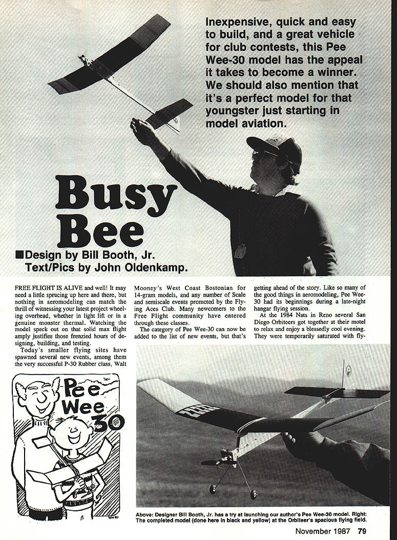
Busy Bee
Design by Bill Booth, Jr. Text/Pics by John Oldenkamp.
FREE FLIGHT IS ALIVE and well! It may need a little sprucing up here and there, but nothing in aeromodeling can match the thrill of witnessing your latest project wheeling overhead, whether in light lift or in a genuine monster thermal. Watching the model speck out on that solid max flight amply justifies those frenzied hours of designing, building, testing.
Today's smaller flying sites have spawned several new events, among them the very successful P-30 Rubber class, Walt Mooney's West Coast Bostonian for 14-gram models, and any number of Scale and semiscale events promoted by the Flying Aces Club. Many newcomers to the Free Flight community have entered through these classes.
The category of Pee Wee-30 can now be added to the list of new events, but that's getting ahead of the story. Like so many of the good things in aeromodeling, Pee Wee-30 had its beginnings during a late-night hangar-flying session.
At the 1984 Nats in Reno several San Diego Orbiteers got together at their motel to relax and enjoy a blessedly cool evening. They were temporarily saturated with flying and playing the casinos, and out of the ideas they bounced around that night came a new proposal. Charlie Yost (longtime Free Flight proponent and McDonnell-Douglas aero engineer) suggested that we develop a low-key gas event using the popular Cox Pee Wee .020 engine. The goals were that it be something fun, simple to build, relatively inexpensive, yet exciting to fly in competition. Charlie threw in one last requirement: it had to have wheels! On the spot it was christened Pee Wee-30—and the fun began.
Within a month, six or so of the little beasts were being flown informally at our local contests. Preliminary rules were drawn up, data was taken on engine performance, and the flight envelope was developed. What emerged was an entry-level gas class that nearly everyone enjoyed building and which seemed worth pursuing beyond the club level. In no time at all the national modeling press picked up on the idea, giving it an additional boost. Very quickly we realized a winner was in the making, but to our surprise the appeal was attracting both experienced and novice fliers, and more than a few of the new contestants were RCers.
After two years of testing, tweaking, and refining the rules—and with the help of our friends, national columnists Ed Whitten, Dave Linstrum, Bob Stalick, et al—the Orbiteers chose 1987 as the year to introduce Pee Wee-30 to the world. We included the Pee Wee-30 in the 1987 national schedule as a special event. The club ponied up $100 for the Pee Wee-30 club champion. The process of formalizing rules grew out of shared experience and trust and reflects its true spirit.
Probably a thousand model designs could be adapted to the Pee Wee-30 formula. Among old-timers and nostalgia subjects, modern designs in addition to wheels—complicated curves and fuselages—can be simply executed with all-sheet construction, although a built-up stick-and-tissue wing will yield better glide. If you want to roll your own, try to keep things simple and straightforward; you will be rewarded with an extremely durable, fun-to-fly ship that won't cost a bundle.
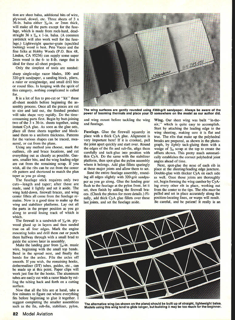
The Busy Bee is a knock-off of Bill Booth's very successful Malibu model. Plans show two versions of construction. Depending on time schedule and skill level, you can build either an all-sheet or stick-and-tissue version. The prototype all-sheet took about 10 hours to finish. Despite being heavily painted, it weighed 102 grams and flew very well during initial tests, though it was slightly tail-heavy. Substituting a stabilizer made from lighter wood brought the center of gravity (CG) to the proper location—and then it flies like the others we've built, with a mild right climb and a fast but hanging glide.
Flight times are around a minute or so in dead air, and well over two minutes in buoyant air. Rise-off-ground (ROG) takeoffs are brisk and safe, and this is one tough little airplane. On one test flight the model was inadvertently sent off with about three seconds of engine run time remaining, resulting in a violent stall and a resounding smack into a truck. A larger, faster ship would have smashed to pieces, but with the Busy Bee the only damage was a small nick in the wing leading edge—and a smidgen of embarrassment on my part.
Building
The following construction guidelines are for the all-sheet Busy Bee as shown on the plans. If this is your first or second model, it might be useful to enlist someone with more experience to help you smooth things out a bit, particularly with the use of instant cyanoacrylate (CyA) glues. They are remarkably easy and fast to use but require a little caution and practice.
Materials and tools
- Wood:
- Three sheets of 3 x 36 in., either 3/32 in. or 2 mm thick, will make all the parts except for the fuselage.
- Fuselage stock: rock-hard, dead-straight 36 in. by 1 in. by 3/16 in. (a common yardstick also works well for the fuselage).
- Use the lightest balsa that is sound and straight. Wherever possible, use medium-grain wood for better handling because it sands well and is slightly tougher.
- Lightweight quarter-grain (speckled-looking) wood is best. Pete Vacco and Hobby Woods (P.O. Box 48, Linden, CA 95236) can supply super 2 mm wood in the 6- to 8-lb. range ideal for these all-sheet projects.
- Other materials: small bits of wire, plywood, dowel, aluminum tubing for axles, fuel reservoir (eye-dropper or glue tip), etc.
- Tools:
- Sharp single-edge razor blades
- 100- and 320-grit sandpaper and a sanding block
- Pliers, ruler or straightedge
- Small drill bits or round files
- Small clamps or pins
- Note: In keeping with the spirit of this category, nothing complicated is called for.
Preparation
It is a lot of fun to pre-cut or "kit" these all-sheet models before beginning the assembly process. Once all the pieces are cut to size and laid out, the finished product will take shape very rapidly. Do the time-consuming parts first.
Begin by butt-joining two of the 3 x 36 in. sheets together using instant CyA glue. As soon as the glue sets, place all three sheets together and block-sand them to a uniform thickness. Patterns for the various shapes can be traced, measured, or cut from the plans.
Mark the outlines, rib and brace locations, and cut everything out as cleanly as possible. Gussets, smaller bits, and the wing leading edge are cut from the remaining scrap. If you wish, all the ribs can be cut from the center rib pattern and shortened to match the plan taper as you go along.
The fuselage stick requires only two cuts—length and taper; after these are made, sand it lightly and set it aside. The wing hold-down, firewall braces, and wing center fillets all come from the fuselage remnants. Make up the wing and stabilizer platforms. Lay out all the parts in the proper position as you go along to avoid losing track of which is which.
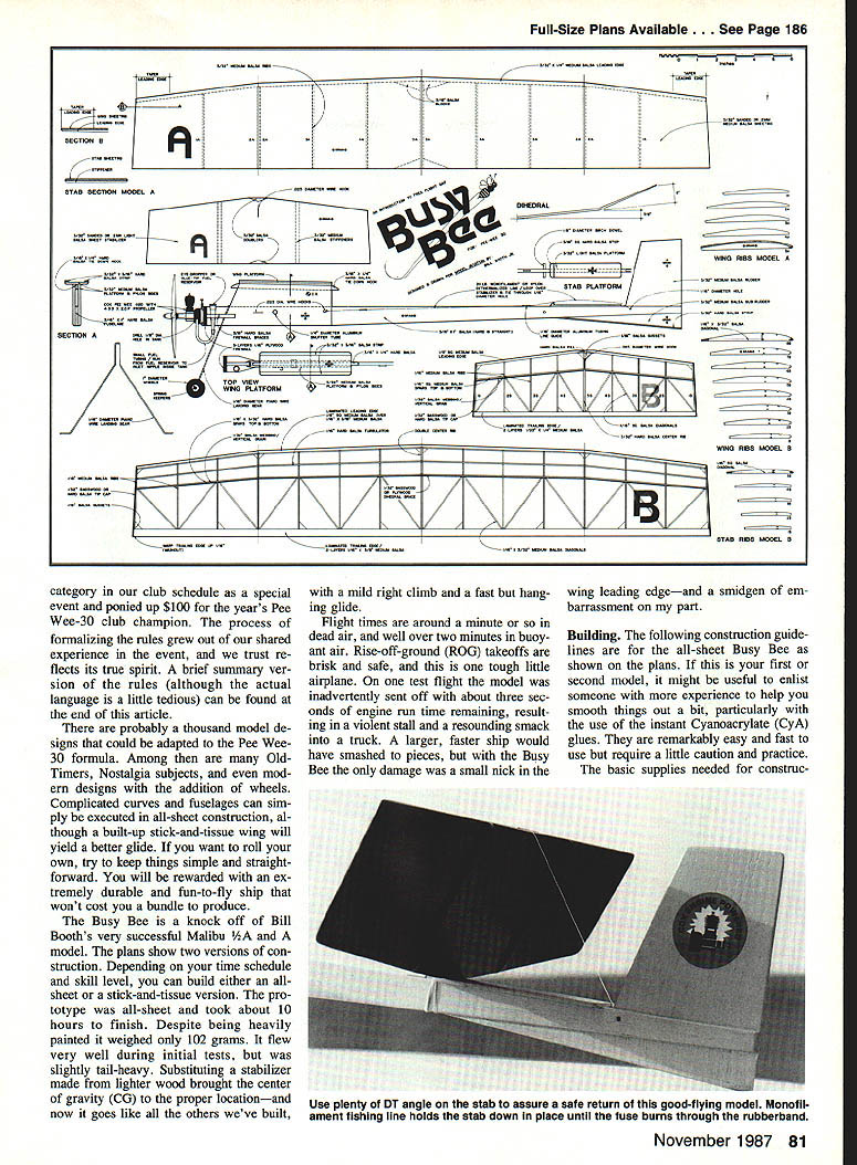
The firewall is a sandwich of 1/16-in. plywood glued up in layers and then sanded true on all four edges. Mark the engine mounting holes and drill them out or punch them halfway through with a small brad to guide the screws later in assembly.
Make the landing gear from 1/16-in. music wire, beginning with the small top bends. Bend in the spread next, and finally the bends for the axles. File the axles smooth. If you wish, the remaining hooks, dethermalizer (DT) tubes, guides, etc., can be made up at this point. Paper clips will work for the hook. The aluminum tubes are easily cut with a razor blade by rolling the tubing back and forth on a cutting surface.
Now that all the bits are at hand, take a few minutes to figure out where everything fits before beginning to glue. Complete the smaller assemblies such as the fin, sub-fin, stabilizer, pylon, and wing mount before tackling the wing and fuselage.
Fuselage
- Glue the firewall squarely in place with thick CyA glue. Alignment is very important—if it is crooked, pull the joint apart quickly and start over.
- Round the edges of the fin and sub-fin, align them carefully, and tack-glue into position with thin CyA.
- Spot-glue the stabilizer platform, then spot-glue the pylon assembly in position.
- Add glue fillets sparingly at these major joints and allow them to set.
- Sand the entire fuselage assembly, rounding all edges slightly with 320-grit sandpaper.
- Glue the landing gear block to the fuselage at the pylon front, let it set, then add the firewall braces.
- Finally add thick CyA glue fillets over these last joints and set the fuselage aside.
Wing
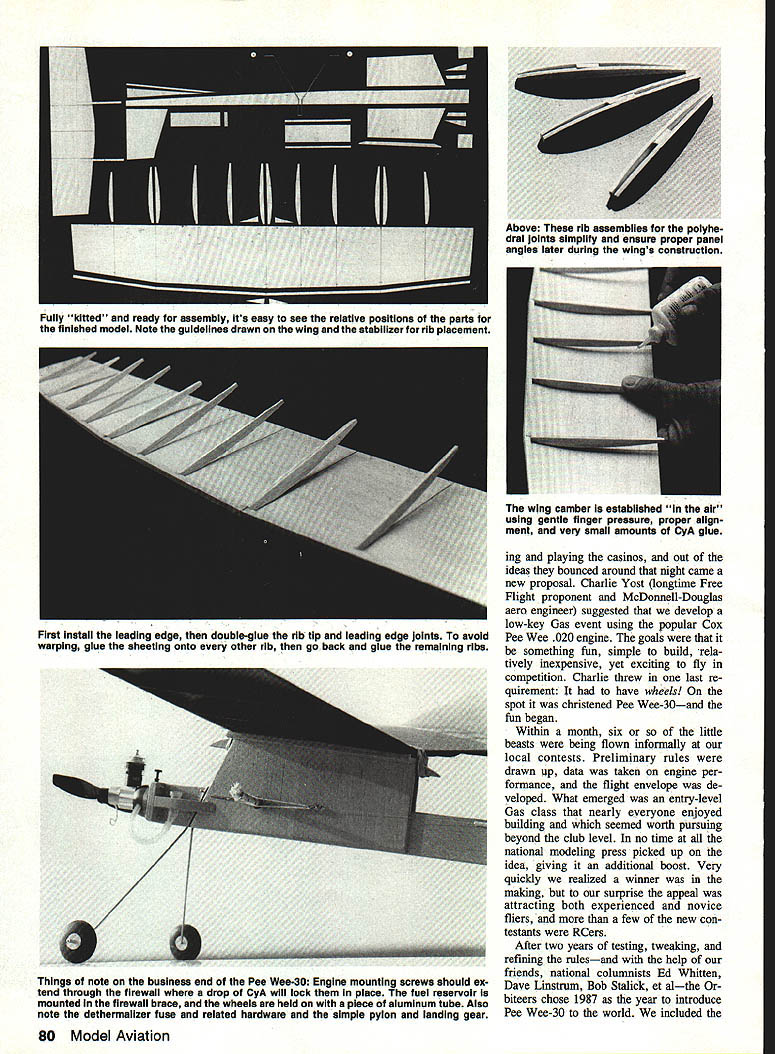
Our sheet wing was built "in-the-air," which is quite easy to accomplish:
- Attach the leading edge to the wing sheeting, making sure it is flat and true.
- Prepare the ribs that make up the polyhedral breaks by lightly tack-gluing them with a wedge of 3/32 scrap at the top to create the required offsets. This pre-establishes the correct polyhedral joint angles.
- Spot-glue the nose of each rib in place at the sheeting/leading edge juncture. Double-glue with thicker CyA on each side as well.
- Form the wing camber by CyA-ing every other rib in place, working out from the center to the tips. Pull and set ribs accurately along the position-locating lines to avoid warps.
- Trim rib ends, sand the entire assembly smooth, and round the edges—particularly at the leading edge. Add triangular pieces on each side of the center ribs.
- Carefully mark and square-cut the wing at the three polyhedral joints. A flexible straightedge helps here; several light cuts work better than one heavy cut.
- Block-sand each joint end straight and true (over the workbench edge or off the end of a glass sanding surface). Test-fit joints and re-sand if necessary.
- Pin down the main panels, leading edge to leading edge, and add the tips propped up 2 in. above the board. Spot-glue tips to main panels, set with thick CyA, then glue top and bottom.
- Repeat at the center joint, blocking each side up with a hunk of standard 1 x 2 in. lumber for the correct angles.
- Dress down the rib bottoms with a sanding block and 320 paper to finish.
Preassemble the model to make sure everything looks right, and correct any misalignments. Drill or hog out holes for DT hardware, hold-down hooks, fuel tank, etc. Test-fit the engine with four #2 wood screws. Once properly fit, remove the engine and set it aside.
Final assembly and finishing
All that remains is painting, trimming, and fuel-proofing.
- The quickest and easiest finishing is Sig Spray clear butyrate or Pactra Aero Gloss spray butyrate dope for color. Alternatives include tissue color trim, K&B Superpoxy, Hobby Poxy, Black Baron Spray Epoxy, etc.
- Don't overdo the finish—keeping the weight down is important, and finishing adds weight quickly.
- Paint outside on a decent dry day. Many finishing materials are quite toxic despite label claims.
To complete assembly:
- Remount the engine.
- CyA the fuel reservoir/tank (an eye-dropper or large glue tip) in place.
- Add remaining hardware including DT line as shown on the plans.
- Install wheels on the axles and use Perfect V-4 retainers to hold them in place.
- Strap it all together with rubber bands.
Flight trimming and testing
- Perform a careful hangar inspection. Check the balance point (CG) and correct it: if rearward of the plan point, add clay to the nose; if forward, add weight to the tail.
- Steam out any bad warps. Make sure the DT works by installing a piece of test fuse and letting it burn through to verify the stab pops up.
- Pick a sunny calm day for the maiden flight, preferably early morning. A field with tall grass is ideal.
- Do a few hand-launched test glides from shoulder height before running the engine.
- Run a couple of tanks of fuel through the system at near-peak rpm. Watch fuel consumption and note the point where it runs out in about four or five seconds; remember this mark.
- Tweak the trailing edge at the third rib bay of the right main wing panel down about 1/16 in. for wash-in and add a small amount (about 1/4 in.) of left rudder.
- Restart the engine, wait for the fuel to drop to the mark, then launch level and smooth. The model should make a smooth power climb to the right, make a slight dip at cutoff, then transition into a smooth descent with a wide left glide.
If trimming is needed:
- Slight looping: add downthrust (a washer or two under the two top engine-mounting screws).
- Severe looping: shim under the trailing edge of the right wing.
- Hard right turn under power: add left thrust to the engine (one or two washers).
- Missing turn in the glide: shim up the stabilizer on the left side.
- Stall at the end of the power climb: recheck balance point, then add a little nose weight.
- Spiral in during glide: check balance point and incidence angles; increase incidence as needed (raise front of wing or back of stab).
One of the beautiful aspects of these all-sheet Pee Wee-30 models is that adjustments can be bent or cut in. Repairs are quite easy with a dab of CyA, and damage in a crash is usually minor. Newcomers are well-advised to take a friend along on early flights.
Safety and flying tips
- Stay well away from cars and spectators at all times.
- Don't do stupid stunts in jest or otherwise.
- When the Busy Bee is trimmed, try a couple of ROG flights pointed dead-straight or slightly left of the prevailing breeze.
Have fun and cheers!
John Oldenkamp 3331 Adams Ave. San Diego, CA 92116
Transcribed from original scans by AI. Minor OCR errors may remain.

