
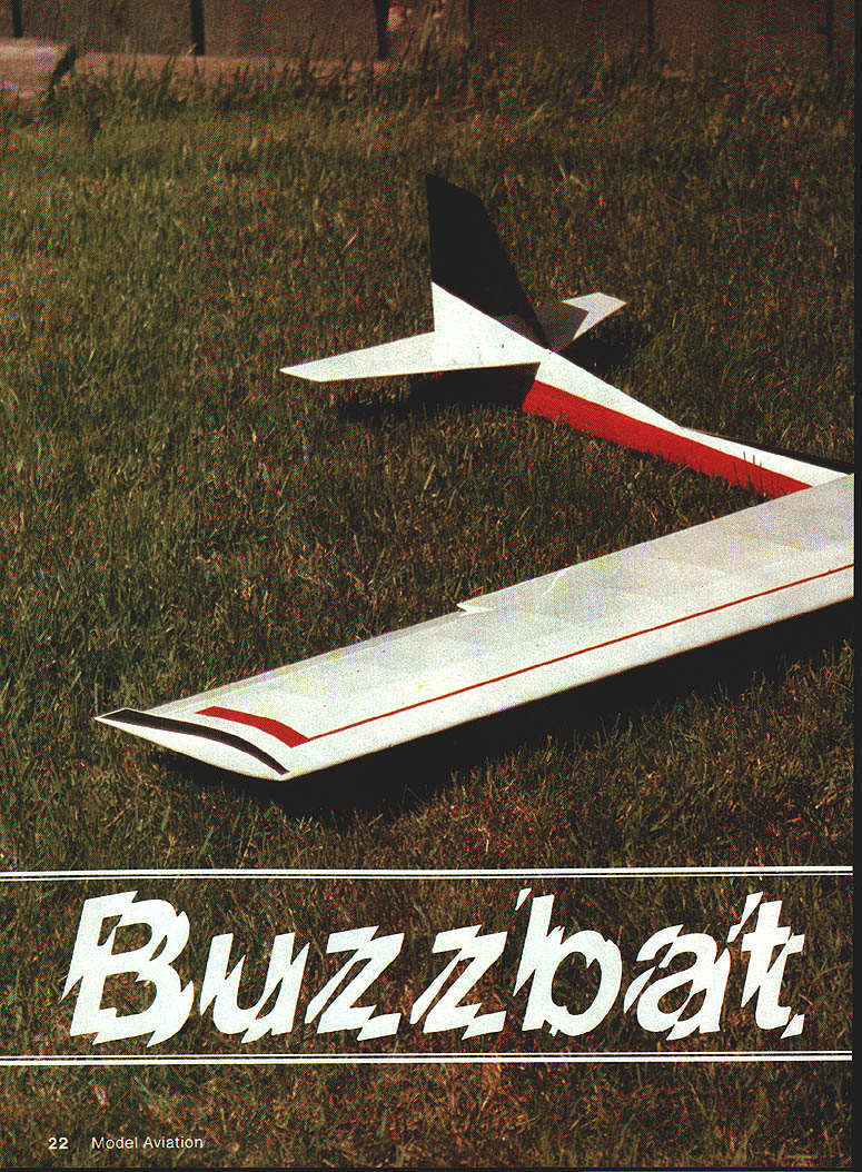
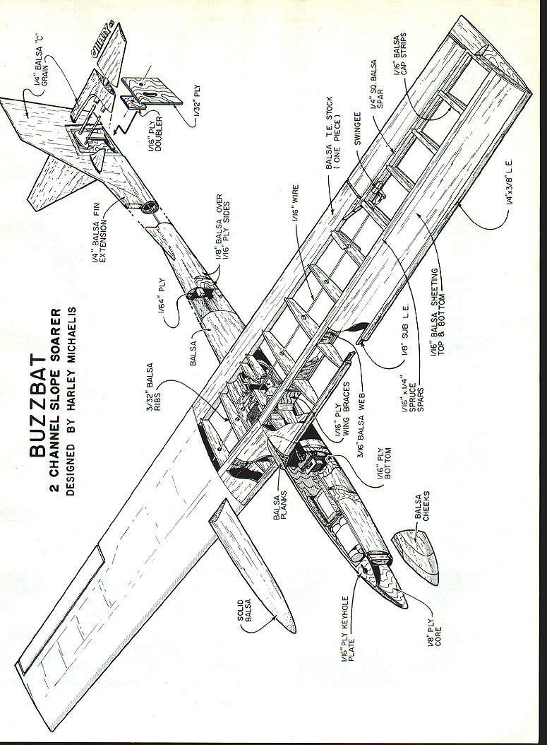
Buzzbat
Designed by Harley Michaelis
Overview
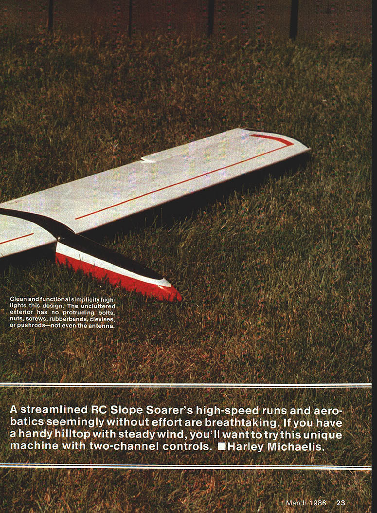
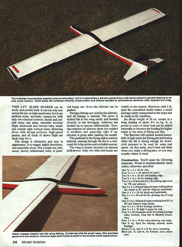
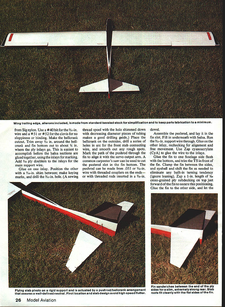
A streamlined, 5-ft (60 in) RC slope soarer, the Buzzbat delivers high-speed runs and aerobatics seemingly without effort. With only two-channel controls it performs inside/outside loops and turns, spins, extended inverted flight, horizontal and vertical rolls, tight vertical turns, blistering dives with abrupt pullouts, high-speed passes, and other showy maneuvers. The design is distinctive, rugged, highly functional and clean—no exposed nuts, bolts, screws, horns or pushrods. Aileron linkage is internal and gapless; the servo is tucked flat in a wing cavity and drives Swingee fittings. Ailerons operate differentially for excellent turning response; the internal pushrod for the flying stab passes through the fin to a bellcrank for crisp action and reliable neutral.
The assembled model is compact for transport. Typical all-up weight is about 26 oz, giving a wing loading near 8½ oz/sq ft. Add a pound or more of sheet lead internally to increase loading for higher winds or more aggressive flying.
Specifications
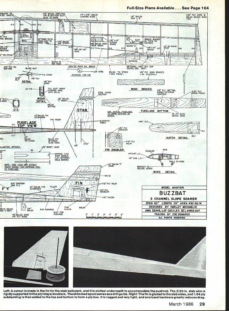
- Span: 60 in
- Length: 39 in
- Area: 450 sq in
- Typical weight: ~26 oz
- Designed by: Harley Michaelis
- AMA 32343, LSF 023 (LEV. 17), NWSS 007
Materials (typical stock)
Wood is medium-density balsa unless noted otherwise.
- One 3/8 x 3 x 36 (ribs)
- Four 3/8 x 3/8 x 36 spruce (spars)
- Two 1/8 x 3 x 36 (sub-leading edge)
- Two 1/4 x 3 x 36 (leading edge)
- Two 1/16 x 1 x 36 beveled trailing-edge stock (TE and ailerons)
- One 3/8 x 3/16 x 36 hard balsa (spar webbing from center R1 to wing tip undersides)
- One 1/2 x 2 x 36 (hatch and underbelly)
- One 3/8 x 3 x 36 soft (fin, decking, top of wing tips)
- One 3/8 x 1/16 x 36 hard (spar webbing from R1 to R9 and interior wing saddle)
- One 1/8 x 4 x 36 (fuselage doublers)
- One 3 x 3 x 36 light C‑grain (stab)
- Four 1/4 x 36 triangular stock (joining fuselage sides, formers, wing ribs, dihedral braces, misc.)
- Four 3/8 x 1/16 x 36 (wing sheeting, cap strips)
- One 1/8 sq. hard (antenna run)
- Spruce 1/2 x 1/4 and 1/4 x 3/8 (servo mounting)
- Birch ply 1/32 (nose center core)
- Birch ply 1/16 x 12 x 48 slab (sides, bottom braces, part bottom sheeting, misc.)
- Birch 1/32 ply inlays (fin)
- Birch ply sub-decking (aft rear former)
- Music wire 1/16 (support)
- Aluminum tubing 1/16 ID (stab)
- Two .055 x 1-1/2 x 36 music wire pushrods (aileron/stab)
- Four metal devices (hardware)
- Six 2-56 threaded couplers (pushrod ends)
- Two Swingees (smaller white Delrin type available)
- 1/4-in sheet metal screws (front hold-down)
- 4-40 blind nut (rear hold-down)
- Two one-piece aileron hinges (fine)
- Three 3/8 x 4-40 round-head bolts (tap size 4-40)
- 4-40 self-tapping screw
- Two Du-Bro A6-in threaded ball links/sockets
- Aluminum strip 1/16 x (wing hold-downs), preferably tempered aircraft aluminum
- Thin sheet metal (for aileron servo bracket)
- Nylon 1/8 x 6-in sheet (Sig stab bellcrank)
- Vinyl seating tape 1/16 x saddle
- Brass .016 sheet (making U around Swingee arms)
- Lead 1/16-in sheet (ballasting, optional)
Construction — Fuselage
- Make a matched pair of 1/16-in. ply fuselage sides. Use the root pattern and mark the wing saddle contour and incidence as shown on the plans.
- Bend the front hold-down per plans. Leave space aft to accept the elevator servo; front former width should accept the servo cross‑wise mounting ears. If desired, a former for the servo may go forward.
- Make 4-in. rails and formers; glue formers to one fuselage side, then invert and assemble the other side for good alignment.
- Cut and attach interior saddle pieces.
- Cut the 1/16-in. ply nose center core; it fits 1/8-in. below the top of the sides. Make matched spacers to fit against the core and sides, glue to the core, and trim for screw-head clearance.
- Cut the ply bottom and mark its centerline. Cut 3/32-in. birch ply hold-down crosspieces to the fuselage width.
- If the servo is small enough to fit forward of the former, cut a rectangle to accept it sideways. Consider a battery-to-receiver adapter to reduce bulky wiring.
- Add triangular stock to inside fuselage edges except at the hatch and aft of the fin front. Join the nose core/spacer assembly to the sides, glue on the bottom with crosspieces.
- Install the compartment divider if desired.
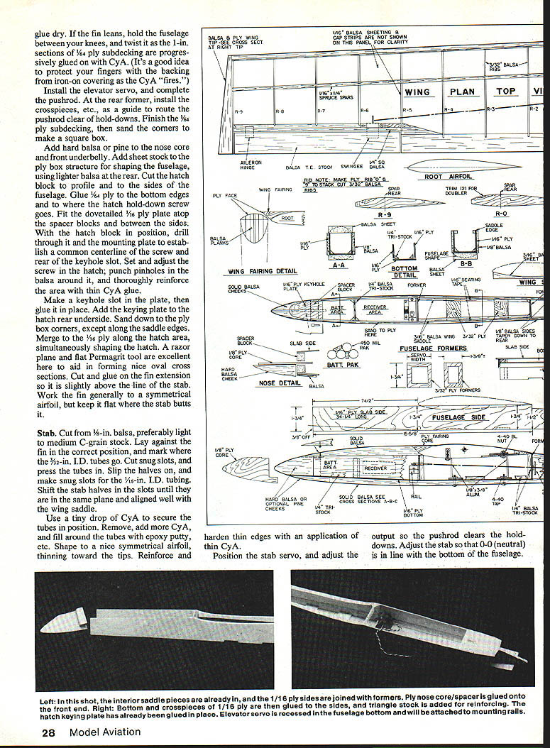
- Install the elevator servo and complete the pushrod. Route the pushrod clear of hold-downs using crosspieces as guides.
- Finish the 1/64-in. ply subdecking and sand corners to make a square box.
- Add hard balsa or pine to the nose core and front underbelly. Add sheet stock to the ply box for shaping; use lighter balsa at the rear.
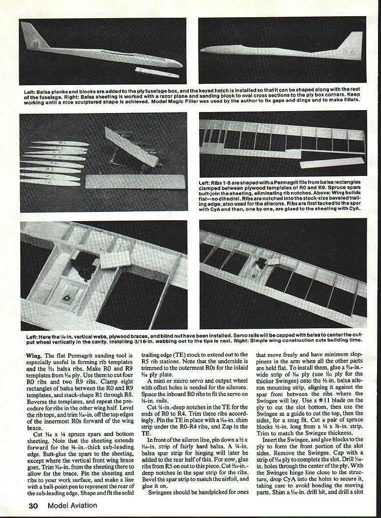
- Cut the hatch block to profile and to the sides. Glue 1/4-in. ply to the bottom edges where the hatch hold-down screw goes. Fit the dovetailed 1/16-in. ply plate and spacer blocks between the sides. With the hatch block in position, drill through it and the mounting plate to establish a common centerline for the screw and the rear of the keyhole slot. Reinforce the area with thin CyA as needed.
- Make and glue in the keyhole slot plate, add the keying plate to the hatch underside, and sand to merge the hatch and fuselage. Use a razor plane and flat Permagrit tool to form nice oval cross sections.
- Cut and glue on the fin extension so it is slightly above the line of the stab. Shape the fuselage and finish the top center sheeting, cap strips, and extreme tips.
Note: Protect your fingers when using CyA; applying the glue in small sections and using backing from iron-on covering helps.
Fin
- Cut the fin shape; it extends to the bottom of the sides.
- Make the Sig nylon bellcrank. Use a #40 bit for the 3/32-in. wire and a #52 for the clevis to avoid sloppiness or binding.
- Make the bellcrank cutout and trim about 1/2 in. around it; cut the fin bottom area to about 1/4 in. where the ply inlays go. Doing this before gluing the balsa sections together and using the inlays for marking is easiest.
- Add 1/16-in. ply doublers to the inlays for the main support wire. Glue on one inlay, position the other with a 1/16-in. shim between, make keying marks, and drill the 3/32-in. hole. A shimmed sewing-thread spool can be used as a drill guide.
- Place the bellcrank on the outsides, drill a series of holes in an arc for the front stab connecting wire, and smooth any rough spots.
- Mark the path of the pushrod through the fin to align it with the servo output arm. Cut the pushrod slot in the fin bottom (a common carpenter's saw works). The pushrod can be made from .055-in. or 1/16-in. wire with threaded couplers on the ends, or with threaded rods inserted in a 3/16-in. dowel.
- Assemble the pushrod and lay it in the fin slot. Fill in underneath with balsa. Run the 3/32-in. support wire through and glue on the other inlay, rechecking alignment and free movement.
- Use CyA to glue the support wire to the inlays.
- Glue the fin to one fuselage side flush with the bottom, trim TS in front of the fin, clamp the fin between the sides and adjust to eliminate built-in turning tendency (ignore slight leaning). Zap a 1-in. length of 1/8-in. cross‑grained ply subdecking on top just forward of the fin to secure position. Glue the fin to the other side and let dry.
If the fin leans after assembly, hold the fuselage between your knees and twist it as 1/64-in. ply subdecking sections are progressively glued on with CyA. Protect fingers when CyA "fires."
Stab
- Cut the stab from 3/16-in. balsa (light to medium C-grain preferred). Lay against the fin, mark where the 5/32-in. I.D. tubes go, and cut snug slots. Press in the tubes and slip the halves on.
- Make snug slots for the 1/16-in. I.D. tubing. Shift the stab halves until they lie in the same plane and align with the wing saddle.
- Use a tiny drop of CyA to secure tubes, then remove, add more CyA, and fill around tubes with epoxy putty or equivalent. Shape to a symmetrical airfoil, thinning toward the tips. Reinforce and harden thin edges with thin CyA.
- Position the stab servo so the pushrod clears the hold-downs. Adjust the stab so 0-0 (neutral) aligns with the bottom of the fuselage.
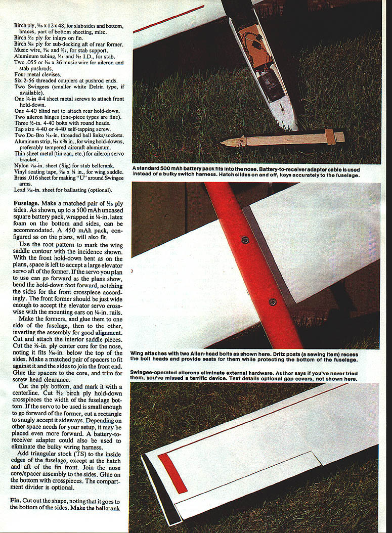
Wing
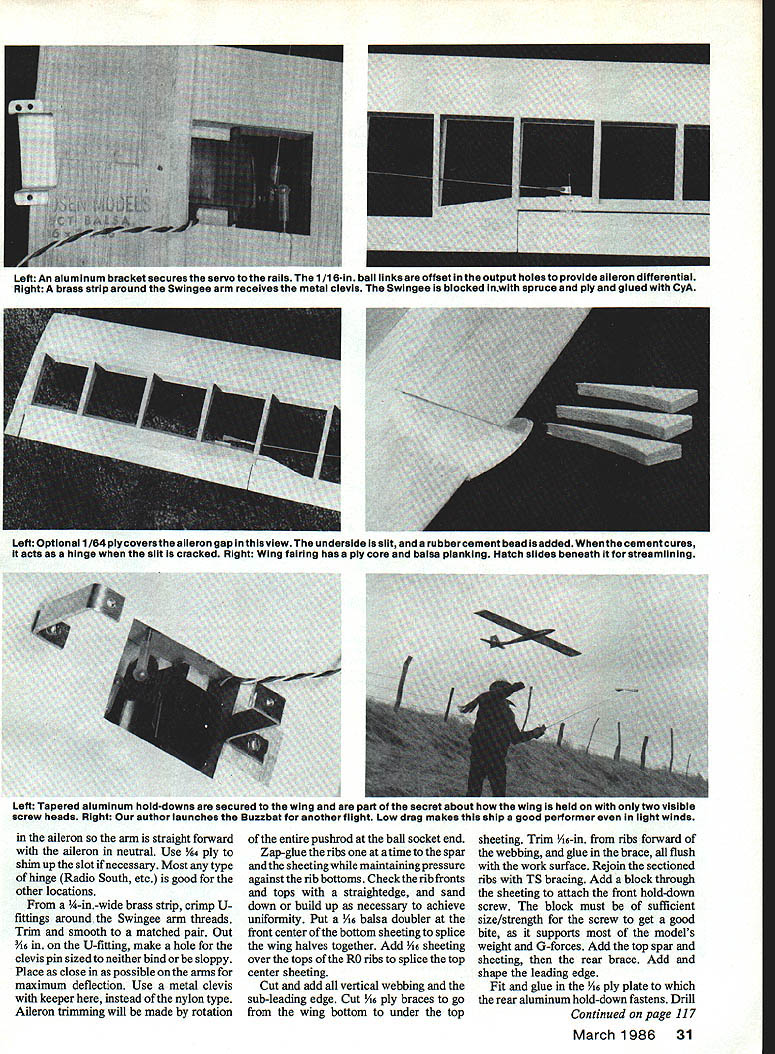
- Make R0 and R9 templates from 1/8-in. ply. Use templates to cut four R0 ribs and two R9 ribs. Clamp eight rectangles of balsa between R0 and R9 templates and stack-shape R1 through R8. Repeat for the other wing half.
- Level rib tops and trim 1/16-in. off top edges of innermost R0s forward of the wing brace.
- Cut 3/16 x 1/4 spruce spars and bottom sheeting. Sheeting extends forward for the 1/2-in.-thick sub-leading edge. Butt-glue spars to sheeting except where vertical front wing brace goes; trim sheeting 1/16-in. there for the brace.
- Pin the sheeting and ribs to the work surface and mark the rear of the sub-leading edge. Shape and fit the solid TE stock to extend to the R5 rib stations. Note: the underside is trimmed to the outermost R0s for inlaid 1/16-in. ply plate.
- Use a mini or micro servo and output wheel with offset holes for the ailerons. Space inboard R0 ribs to fit the servo on 1‑1/4-in. rails.
- Cut 1/4-in.-deep notches in the TE for ends of ribs R0 to R4 and trim ribs accordingly. Pin the TE in place with a 1/16-in. shim strip under R0‑R4 ribs and Zap in the TE.
- In front of the aileron line, pin down a 1/2 x 1/16-in. strip of fairly hard balsa. Glue ribs from R5 outward to this piece. Cut 3/32-in. deep notches in the spar strip for ribs, bevel the strip to match the airfoil, and glue.
- Cut and install webbing, sub-leading edge, and 1/8-in. ply braces from wing bottom to under top sheeting. Trim 1/16-in. from ribs forward of the webbing and glue in the brace flush with the work surface. Rejoin sectioned ribs with TS bracing.
- Add a block through the sheeting to attach the front hold-down screw; size/strength is important to withstand G-loads. Add top spar and sheeting, then rear brace, and shape the leading edge.
- Put a 1/16-in. balsa doubler at the front center of the bottom sheeting to splice wing halves; add 1/8-in. sheeting over top of 1/16-in. ribs to splice top center sheeting. Fit and glue the 1/16-in. ply plate for the rear aluminum hold-down fastener. Drill a hole for the 4-40 blind nut near the plate front at wing center.
- Make the rear hold-down from tempered aircraft-grade aluminum if available. Center punch bent ends about 3/16 in., drill 3/32-in. holes and tap for 4-40 threads. Temporarily attach the hold-down and set the wing in the saddle to mark fuselage bottom hold-down holes. Drill with the fuselage resting on a block. Glue notched ply plates to the fuselage and rear them so they can’t rotate when installing final hold-downs.
- Extend bottom sheeting toward the aileron servo to minimize open area. Glue a 5/8 x 1/4 x 1/8-in. piece of 1/8-in. ply centered inside to extend the ply plate and adjacent bottom sheeting. Drill for the 4-40 blind nut. Attach a 4-40-in. balsa vertical crosspiece aft of the servo and add triangular stock where the ply plate meets other bottom sheeting.
Note: The most common landing damage is the ply plate breaking away—ensure adequate reinforcement.
Ailerons and Swingees
- Cut the ailerons from the wing to plan outline and hinge them using one-piece fabric or plastic hinges or the Swingee arrangement.
- Select Swingees that move freely and have minimum sloppiness. Install by gluing a 1/16-in. wide strip of ply onto the 1/4-in. balsa aileron mounting strip, aligning it against the spar front between ribs where the Swingee will sit. For thicker Swingees use 1/32-in. ply.
- Cut slot top and bottom with a #11 blade, pin sides for a snug fit, and glue spruce blocks to form front slot sides. Cap with 1/16-in. ply and drill 1/16-in. holes through the center of the ply. Drop CyA into the holes to secure the Swingee while avoiding bonding moving parts.
- Drill a pintle slot and finish pintle hole with a 1/16-in. drill; align the arm holes with aileron horn locations.
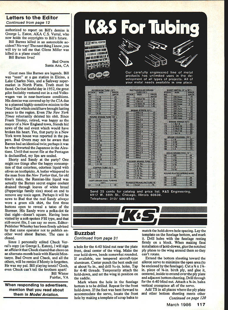
- From 1/4-in.-wide brass strip, crimp U-fittings around Swingee arm threads. Trim and make a clevis-pin hole about 1/8 in out on the U-fitting; place as close to the arm as possible for maximum deflection. Use a metal clevis with keeper. Aileron trimming can be made by rotating the entire pushrod at the ball-socket end.
- Zap-glue the ribs one at a time to the spar and sheeting while maintaining pressure against rib bottoms; check fronts and tops with a straightedge.
- Cut pushrod wire paths through ribs, use couplers with sufficient threads for adjustment and solder the coupler to the wire at the aileron end. Fit a metal clevis centered on the threads with a keeper. With radio on and output wheel neutral, mark and cut servo-end wires to go deep into the couplers; cut and epoxy wires in the couplers.
- To avoid bonding Swingee moving parts, secure rear portions by dropping CyA through small holes made in the balsa.
Aileron servo installation and differential
- Glue rails to the inside of inboard R0 ribs, centering the servo output wheel vertically in the cavity. A metal bracket screws over the servo case from the underside.
- A cutout in the sheeting over the servo wheel provides an extra 1/16-in. of space.
- Butt the servo bottom against the rear brace so cable clears the front hold-down.
- Provide aileron differential (more up than down) by placing 1/16-in. ball links in offset holes in the output wheel. Try about 45° setting to get at least twice as much up travel as down to avoid adverse yaw.
- Use a hole radius of at least 5/16 in. to get sufficient aileron movement.
- For small wing Swingees, one control wire will run high and one low to the ball links; for bulkier opposing Swingees both ball links can be on top or bottom of the wheel (prefer bottom for access).
- Study servo rotation and Swingee action from the plane’s rear with the radio on to verify linear movement increases correctly.
Optional aileron gap covers
- After covering ailerons, cut a 3/4-in.-wide strip of thin rigid plastic (3-mil clear drafting Mylar recommended).
- Attach with 1/2-in.-wide double-sticky clear Scotch tape. These strips can be external or under the wing covering if low heat is used.
- To apply: tape the plastic strip to the work surface with small bits of tape on one edge, stretch and apply double-stick tape to the opposite long edge. Remove the holding tape, position over the gap and slowly lower in place, trim excess.
Note: Static electricity requires a clean work environment and careful handling.
Finishing
- Use durable "tex" coverings for the fuselage in preference to unreinforced films. A single 8-in.-wide piece can cover the fuselage; make overlaps forward of the fin and around the nose.
- Protect raw bolt-hole edges with a large washer, eyelet or bushing with a broad flange. Dritz Mighty Snaps (size 24) posts are suitable.
- Pack the battery and receiver with 1/4-in. dense latex foam on three sides and front. Hollow the hatch underside if necessary.
- Run the antenna down the fuselage on a 1/8-in. balsa stick. Consider using a battery-to-receiver adapter in lieu of a switch harness; a full charge should give 3–4 hours of operation.
Balance and trim
- If the saddle is cut per plans the wing has 1° incidence. With the stab at 0° neutral there is little tendency to balloon; fly the ship out of its heading.
- Use a 450 or 500 mAh pack and 5/16-in. sheet lead squares forward of the battery for balancing if required.
- Balance at the plan CG location and use adequate stab throw for spins. For low-time pilots, start with the model balanced at the spar and trim elevator for level flight.
- Keep initial stab throw small—about 1/8-in. each way—as the ship is touchy in pitch. Increase throw later for tighter spins and turns.
- If your transmitter has dual-rate, use it to limit throws for safer handling.
- The fin size on the plans provides adequate directional stability at speed; larger fins may hamper spins.
- If wing tip walk occurs, increase aileron differential.
- If bottom ballast is used, larger grommets on wing hold-downs can be adjusted vertically to secure lead to the fuselage bottom. Fold and trim sheet lead weights to maintain the desired balance point.
Notes and tips
- Aileron trimming is done by rotating the pushrod at the ball-socket end.
- Use metal clevises and keepers at the aileron end rather than nylon types for reliability.
- When installing Swingees, shim and secure pintle holes carefully to avoid binding.
- The ply plate that holds the rear hold-down bears most of the model’s weight and G-forces—ensure it is well reinforced.
- The wing fairing ply facing can be shaped tack-glued to the hatch rear, broken away and glued to the leading edge while the wing is mounted. Use Magic Model Filler to smooth joints and temporary 1/16-in. seating tape to get a good merge between hatch and fairing.
Left/right photos in the original plans show the fin cutout for the stab bellcrank with a slotted underside to accommodate the pushrod; the 3/32-in. stab wire is rigidly supported in ply inlays/doublers. The fuselage is assembled as a lightweight ply box with enclosed hardware to reduce drag.
Transcribed from original scans by AI. Minor OCR errors may remain.

