
Cabin Fever
Jim Miller
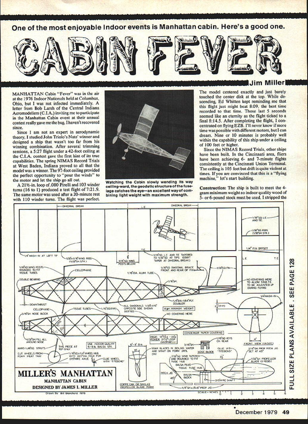
One of the most enjoyable indoor events is Manhattan Cabin. Here's a good one.
MANHATTAN Cabin "Fever" was in the air at the 1976 Indoor Nationals held at Columbus, Ohio, but I was not infected immediately. A letter from Bob Larsh of the Central Indiana Aeromodellers (C.I.A.) inviting me to participate in the Manhattan Cabin event at their annual contest really gave me the bug. I haven't recovered since.
Since I am not an expert in aerodynamic theory, I studied John Triolo's Nats' winner and designed a ship that wasn't too far from his winning combination. After several trimming sessions, a 5:27 flight under a 42-foot ceiling at the C.I.A. contest gave the first hint of its true capabilities. The spring NIMAS Record Trials at West Baden, Indiana proved to all that the model was a winner. The 97-foot ceiling provided the perfect opportunity to "pour the winds" to the motor and let the ship go all out.
A 21½-in. loop of .080 Pirelli and 103 winder turns (16:1) produced a test flight of 7:21.9. The same motor was used after a 20-minute rest with 110 winder turns. The flight was perfect.
The model centered exactly and just barely touched the center disk at the top. While descending, Ed Whitten kept reminding me that this flight just might beat 8:09, the best time recorded to that time. Those last 5 seconds seemed like an eternity as the flight ticked to a final 8:14.5. After completing the flight, I concentrated on flying EZB. I'll never know if more time was possible with different motors, but I can dream. Nine or ten minutes is probably well within the capability of this ship under a ceiling of 100 feet or higher.
Since the NIMAS Record Trials, other ships have been built. In the Cincinnati area, fliers have been achieving 6- and 7-minute flights consistently at the Cincinnati Union Terminal. The ceiling is 105 feet but drift is quite violent at times. If you are convinced that this is a "flying machine," let's start building.
Construction
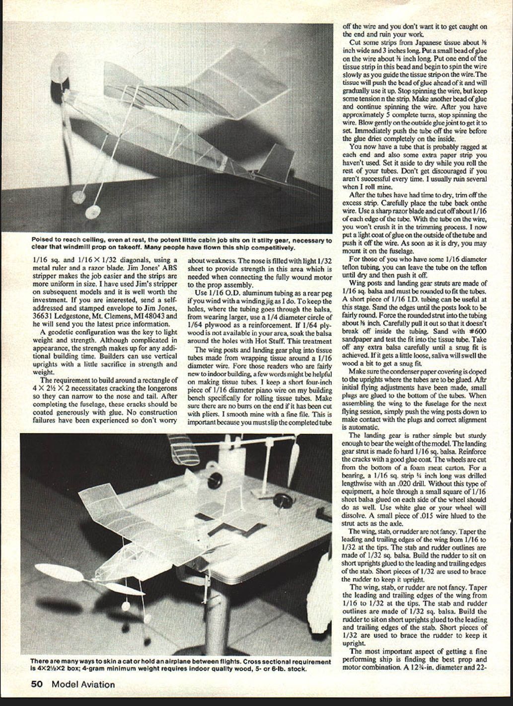
The ship is built to meet the 4-gram minimum weight, so indoor-quality wood of 5- or 6-pound stock must be used. I stripped the 1/16" square and 1/16" x 1/32" diagonals, using a metal ruler and a razor blade. Jim Jones' ABS stripper makes the job easier and the strips are more uniform in size. I have used Jim's stripper on subsequent models and it is well worth the investment. If you are interested, send a self-addressed and stamped envelope to Jim Jones, 36631 Ledgestone, Mt. Clemens, MI 48043 and he will send you the latest price information.
A geodetic configuration was the key to light weight and strength. Although complicated in appearance, the strength makes up for any additional building time. Builders can use vertical uprights with a little sacrifice in strength and weight.
The requirement to build around a rectangle of 4 x 2½ x 2 necessitates cracking the longerons so they can narrow to the nose and tail. After completing the fuselage, these cracks should be coated generously with glue. No construction failures have been experienced so don't worry about weakness. The nose is filled with light 1/32" sheet to provide strength in this area which is needed when connecting the fully wound motor to the prop assembly.
Use 1/16" O.D. aluminum tubing as a rear peg if you wind with a winding jig as I do. To keep the holes where the tubing goes through the balsa from wearing larger, use a 1/4" diameter circle of 1/64" plywood as a reinforcement. If 1/64" plywood is not available in your area, soak the balsa around the holes with Hot Stuff. This treatment makes the wing posts and landing gear plug into tissue tubes made from wrapping tissue around a 1/16" diameter wire.
Making Tissue Tubes (step-by-step)
For readers new to indoor building, a few words might be helpful on making tissue tubes.
- Keep a short four-inch piece of 1/16" diameter piano wire on your bench specifically for rolling tissue tubes. Make sure there are no burrs on the end if it has been cut with pliers; smooth it with a fine file. This prevents the tube from catching on the end when you try to slip it off the wire.
- Cut strips from Japanese tissue about 3/8" wide and 3" long.
- Put a small bead of glue on the wire about 3/8" long. Place one end of the tissue strip in this bead and begin to spin the wire slowly as you guide the tissue strip on the wire. The tissue will push the bead of glue ahead of it and gradually use it up.
- Stop spinning the wire but keep some tension on the strip. Make another bead of glue and continue spinning the wire. After you have approximately five complete turns, stop spinning the wire. Blow gently on the outside glue joint to get it to set. Immediately push the tube off the wire before the glue dries completely on the inside.
- Set the tube aside to dry while you roll the rest. Don't get discouraged; you may ruin several when learning.
- After the tubes have dried, trim off the excess strip. Carefully place the tube back on the wire. Use a sharp razor blade and cut off about 1/16" of each edge of the tube. With the tube on the wire, you won't crush it while trimming.
- Put a light coat of glue on the outside of the tube and push it off the wire. As soon as it is dry, you may mount it on the fuselage.
- If you have 1/16" diameter Teflon tubing, you can leave the tube on the Teflon until dry and then push it off.
Wing Posts and Landing Gear
Wing posts and landing gear struts are made of 1/16" square balsa and must be rounded to fit the tubes. A short piece of 1/16" I.D. tubing can be useful at this stage. Sand the edges until the posts look fairly round. Force the rounded strut into the tubing about 3/16", then carefully pull it out so it doesn't break off inside the tubing. Sand with #600 sandpaper and test the fit into the tissue tube. Remove any extra balsa carefully until a snug fit is achieved. If it gets a little loose, saliva will swell the wood slightly to obtain a snug fit.
Make sure the condenser-paper covering is doped to the uprights where the tubes are to be glued. After initial flying adjustments have been made, small plugs are glued to the bottom of the tubes. When assembling the wing to the fuselage for the next flying session, simply push the wing posts down to make contact with the plugs and correct alignment is automatic.
The landing gear is simple but sturdy enough to bear the weight of the model. The landing gear strut is made of hard 1/16" square balsa. Reinforce the cracks with a good glue coat. The wheels are cut from the bottom of a foam meat carton. For a bearing, a 1/16" square strip 1/4" long was drilled lengthwise with a .020" drill. Without this type of equipment, a hole through a small square of 1/16" sheet balsa glued on each side of the wheel should work as well. Use white glue on your wheel or it will dissolve. A small piece of .015" wire glued to the strut acts as the axle.
Wing, Stab, and Rudder
The wing, stab, and rudder are not fancy. Taper the leading and trailing edges of the wing from 1/16" to 1/32" at the tips. The stab and rudder outlines are made of 1/32" square balsa. Build the rudder to sit on short uprights glued to the leading and trailing edges of the stab. Short pieces of 1/32" are used to brace the rudder to keep it upright.
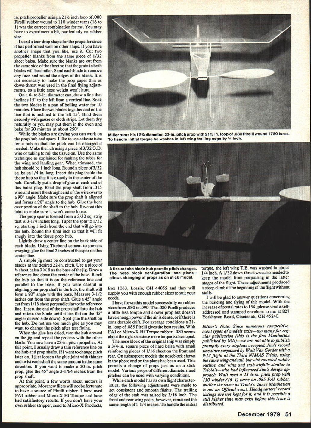
The most important aspect of getting a fine-performing ship is finding the best prop and motor combination. A 12¾-in. diameter, 22-in. pitch propeller using a 21½-in. loop of .080 Pirelli rubber wound to 110 winder turns (16:1) was the correct combination for me. You may have to experiment, particularly on rubber size.
Propeller Construction and Hub
I used a teardrop shape for the propeller since it has performed well on other ships. If you have another shape you like, use it.
- Cut two propeller blanks from the same piece of 1/32" sheet balsa. Make sure the blanks are cut from the same side of the sheet so that the grain in both blades will be similar.
- Sand each blade to remove any fuzz and round the edges. It is not necessary to make the prop paper-thin as down-thrust was used in the final flying adjustments, so a little nose weight won't hurt.
- On a 6- to 8-in. diameter can, draw a line that inclines 15° to the left from a vertical line. Soak the two blades in a pan of boiling water for 10 minutes. Place the wet blades together on the line that is inclined 15° left. Bind them securely with gauze or cloth strips. Let them dry naturally or bake for about 20 minutes at 250°F.
While the blades are drying you can work on the prop hub and spars. I like to use a tissue tube for a hub so that the pitch can be changed if needed.
- Make the hub using a piece of 3/32" O.D. wire or tubing to roll the tissue on. Use the same technique as explained for making the tubes for the wing and landing gear. When trimmed, the hub should be 1 inch long.
- Round a piece of 3/32" square balsa 1/4" long. Insert this plug inside the tissue hub so that it is exactly in the center. Put a drop of glue at each end of this balsa plug. Bend the prop shaft from .015" wire and insert the straight end, bending it over 90°. Make sure the prop shaft is aligned and forms a 90° angle to the hub. Glue the bent-over portion of the shaft to the hub and re-coat this joint to make sure it won't come loose.
- The prop spar is formed from a 3/32" square strip that is 3-1/4 inches long. Taper the spar to 1/32" square starting 1 inch from the end that will go into the hub. Round this final inch so that it fits snugly into the tissue prop hub.
- Lightly draw a center line on the back side of each blade. Using Titebond cement to prevent warping, glue the final 2 inches of the spar on this center line.
A simple jig must be constructed to get your blades at the desired 22-in. pitch:
- Use a piece of 1/8" sheet balsa 3 x 8 as the base of the jig. Draw a reference line down the center of the base. Block the hub so that it is on the reference line and parallel to the base. If you were careful in aligning your prop shaft in the hub, the shaft will form a 90° angle with the base.
- Measure 3-1/2 inches out from the prop shaft. Glue a 45° angle cut from 1/16" sheet perpendicular to the reference line. Insert the end of the prop shaft into the hub and rotate the blade until it lies flat on the 45° angle (curved side down). Spot glue the shaft on the hub. Do not use too much glue as you may want to change the pitch after test flying.
- When the glue has dried, turn the hub around on the jig and repeat the process with the other blade. You now have a 22-in. pitch propeller.
I usually draw a thin reference line on the hub and prop shafts. If I want to change pitch later, I loosen the glue joint with thinner and twist each shaft the same amount in the same direction. To make a 20-in. pitch prop, glue the 45° angle 3-1/4 inches from the prop shaft.
Motors and Rubber
Most new fliers will not be fortunate to have a source of Pirelli rubber. I have used FAI rubber and Micro-X Hi Torque and have had satisfactory results. If you don't have your own rubber stripper, send to Micro-X Products, Box 1063, Lorain, OH 44055 and they will supply you with enough rubber sizes to suit your needs.
I have flown this model successfully on rubber sizes from .080 to .090. The .080 Pirelli produces a little less torque and a slower prop but doesn't have enough power if the air is dense or if there is considerable drift. For average conditions a 21-in. loop of .085 Pirelli gives the best results. With FAI or Micro-X Hi Torque rubber, .080 seems about the right size since more torque is developed.
The nose block of the original ship was simply a 3/4-in. square piece of hard balsa with small reinforcing pieces of 1/16" sheet on the front and rear. On subsequent models the nose block shown in the photo and on the plans has been used. This permits a change of props just as on a stick model. Various props of different diameters and pitches can be used with varying conditions.
Final Adjustments
While each model has its own flight characteristics, the following adjustments were made to get consistent and smooth flights:
- Raise the trailing edge of the stab by 3/16".
- Keep the front and rear wing posts at 1-1/4" length.
- To handle the initial torque, wash in the left wing trailing edge about 1/4".
- Use 1/32" down-thrust to keep the model from porpoising in the latter stages of the flight.
These adjustments produced a steep climb at the beginning of the flight without stalls.
I will be glad to answer questions concerning the building and flying of this model. With the increase of postal rates to 15¢, please send a self-addressed and stamped envelope to me at 827 Yorkhaven Road, Cincinnati, OH 45240.
Editor's Note
Since numerous competitive-event types of models exist—too many for regular publication (this is the first Manhattan published by MA)—we are not able to publish promptly every airplane accepted. Jim's model was since surpassed by Walt Van Gorder with a 9:13 flight at the Third NIMAS Trials, using the same wing and tail, but with rounded rudder outline and wing and stab airfoils similar to Triolo's—who had influenced Jim's design approach. Walt used a 23½-in. pitch prop with 130 winder turns (16:1) on .085 FAI rubber and posted 9:13. This is not an official event; Headquarters' records are not kept for it, and it is possible a still higher time may exist before this issue is distributed.
Transcribed from original scans by AI. Minor OCR errors may remain.

