
CaBInair
Introduction
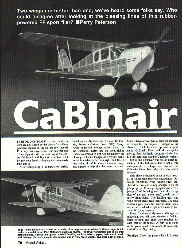
FREE FLIGHT scale or sport modelers who are not stirred by the sight of a rubber-powered biplane in the air are few indeed. One of the biggest thrills in modeling is the successful launch and flight of a biplane built by your own hands.
After completing a construction article based on the Sig Cabinaire kit (see Bostonair, Model Aviation, June 1988), Larry Kruse suggested another project based on the Cabinaire. He felt the great-flying Cabinaire seemed to beg for another set of wings. The result: a Cabinaire variant christened CaBInair. This is not a true enlargement of the Cabinaire; it is larger and captures the Cabinaire flavor while including many differences.
This plane is designed as an outdoor model, so select balsa materials accordingly. Fuselage longerons, wing leading edges, landing gear and wing mount areas should be firm and strong. Fuselage uprights and crosspieces aft of the wing area (except the rear motor peg) may be fairly light balsa. The nose is a good place for heavier balsa—most models need added weight in the nose to balance for flying.
Even if you are fairly new to this type of modeling, you will soon develop a feel for balsa strength and grain type required for each part. A very good study of balsa grain and its uses is included in the Sig catalog.
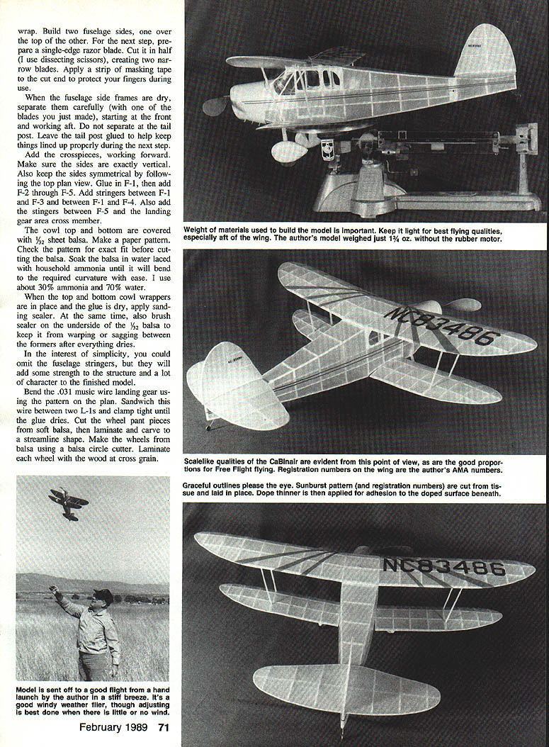
The author's model weighed just 1 3/4 oz without the rubber motor.
Materials and general notes
- Use firm balsa for fuselage longerons, wing leading edges, landing gear and wing mount areas.
- Use fairly light balsa for fuselage uprights and crosspieces aft of the wing (except the motor peg).
- Keep weight light, especially aft of the wing.
- Study balsa grain direction; it influences strength and bending characteristics.
Fuselage
- Cover the plan with thin kitchen wrap (to prevent glue sticking to the plan).
- Build two fuselage side frames, one over the other.
- Prepare two narrow razor blades by cutting a single-edge blade in half (dissecting scissors work). Apply a strip of masking tape to the cut end to protect your fingers.
- When the side frames are dry, carefully separate them starting at the front and working aft. Do not separate at the tail post—leave the tail post glued to help keep things aligned.
- Add the crosspieces, working forward. Make sure the sides are exactly vertical and symmetrical following the top plan view.
- Glue in F-1, then add F-2 through F-5.
- Add stringers between F-1 and F-3, between F-1 and F-4, and between F-5 and the landing-gear-area cross member.
- Cowl top and bottom: make a paper pattern first and check fit before cutting 1/32" sheet balsa.
- Soak the balsa in water with household ammonia (about 30% ammonia, 70% water) until it bends to the required curvature easily.
- Place top and bottom cowl wrappers, glue and dry; apply sanding sealer at the same time.
- Brush sealer on the underside of the 1/32" balsa to keep it from warping or sagging between formers after drying.
- Note: You could omit the fuselage stringers for simplicity, but they add strength and character.
Landing gear and wheels
- Bend .031" music wire landing gear using the pattern on the plan.
- Sandwich the wire between two L-1s and clamp tight until the glue dries.
- Cut wheel pant pieces from soft balsa, laminate and carve to a streamline shape.
- Make wheels from balsa using a balsa circle cutter; laminate each wheel with the wood at cross grain.
- Cut a groove in the back of each wheel pant so the short vertical portion of the landing gear wire can be recessed.
- After wheels are sanded, sealed, and painted, trap them in the wheel pants with the landing gear wire and apply quick-set epoxy sparingly where the wire is recessed in the groove. This prevents the pants from sagging.
- Brush on three or four coats of sanding sealer to the wheel pants, sanding between coats before painting.
- Cover the wheels with masking tape when painting.
- Paint suggestion: Pactra yellow enamel spray (plastic model supplies); apply a couple of light coats—use just enough to cover to avoid excess weight.
- Glue the landing gear assembly to the fuselage at the location shown on the plans.
Flying surfaces
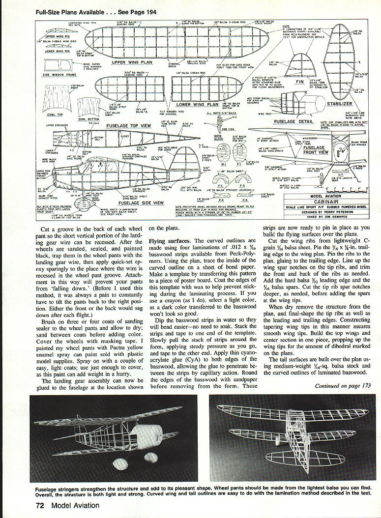
- Curved outlines: make using four laminations of .012" x 1/16" basswood strips (available from Peck-Polymers).
- Trace the inside of the curved outline on bond paper and transfer to poster board to make a template.
- Coat template edges with wax (crayon works) to prevent sticking.
- Dip basswood strips in water (no need to soak); stack strips and tape one end to the template.
- Pull stack around the form, apply steady pressure and tape the other end.
- Apply thin cyanoacrylate glue (CYA) to both edges, allowing capillary action to penetrate between strips.
- Round edges with sandpaper before removing from the form; these strips are then ready to pin in place.
- Wing ribs: cut from lightweight C-grain 1/16" balsa sheet.
- Pin the 5/16" x 1/8" trailing edge to the wing plan.
- Pin ribs to the plan and glue to the trailing edge.
- Line up wing spar notches on the tip ribs and trim as needed.
- Add the hard balsa 3/32" leading edge and the 1/16" balsa spars.
- Cut tip rib spar notches deeper as needed before adding spars and wing tips.
- When dry, remove structure from the plan and final-shape tip ribs, leading and trailing edges.
- Build tip wings and center section in one piece, propping up the wing tips for the dihedral marked on the plans.
- Tail surfaces: build over the plan using medium-weight 1/16" balsa stock and the laminated basswood curved outlines.
Covering
- Prepare by brushing clear dope anywhere you plan to glue tissue (this seals the wood so glue/water solution doesn't soak in and warp surfaces).
- Select a good quality tissue—yellow Japanese tissue (Old-Timer Models) recommended.
- Ensure tissue grain is spanwise on flying surfaces and lengthwise on the fuselage. If unsure, tear a small piece to detect the grain.
- Avoid heavier domestic tissues that have little grain and are heavier.
- Use a soft watercolor brush to apply a 50% white glue / 50% water solution to the outside of the framework for each area to be covered.
- Lay tissue over the framework and gently pat down, easing out wrinkles.
- When dry, trim excess tissue with a sharp razor blade.
- Do not cover the lower wing mount area—doped tissue will not bond well enough to the glue used to attach the wing.
- Shrink the tissue by misting lightly with water (use an adjustable plastic spray bottle). Do not saturate—only a little sag is desired.
Finishing
- Brush on a thinned coat of non-shrink dope (Sig Lite-Coat or a non-shrink nitrate dope are good choices).
- Decorative details:
- Sunburst stripes and registration numbers cut from tissue and applied over dope; use thinned dope to adhere.
- Windshield: trace pattern on bond paper, test fit, then transfer to acetate.
- Attach windshield with RC/56 glue sparingly to the back and lower side portions only. Do not glue the bottom front where it comes up around the cowl top.
- After lower sides and back are dry, glue the top to the fuselage cross member at the wing front location.
- A 1/32"-wide red adhesive-backed RC decorating tape works well for the stripe on the windshield bottom.
- Side window frames: cut from bond paper, paint same color as fuselage, glue thin acetate to the back side, then glue assembly in place.
- Fuselage stripes: use 1/2" wide red adhesive-backed decorating tape from RC model supplies; fix with hot air from a blower dryer. Drafting decorating tape usually will not stick or withstand handling as well.
Final assembly
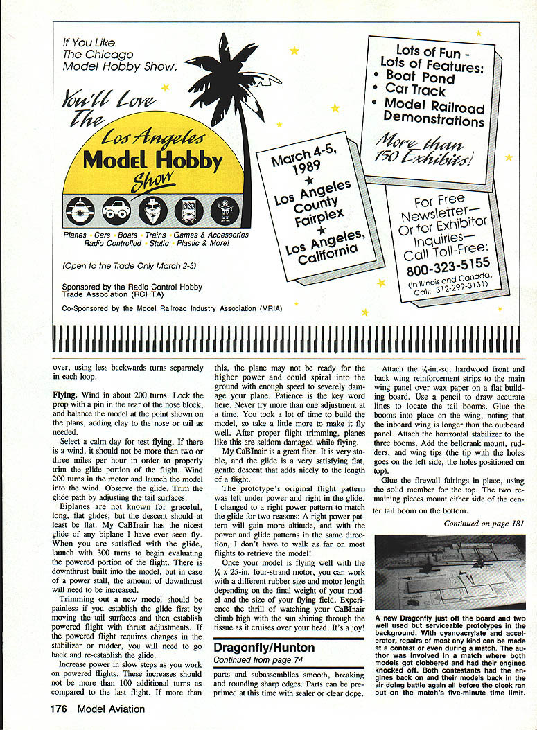
- Attach the top wings to the fuselage by applying glue to the four corners of the center section.
- Glue the horizontal tail in place, making sure everything is straight and true.
- Measure from wing tip to tail tip on each side to ensure squareness and sight down the fuselage from back to front.
- When dry, turn the plane upside down and attach the bottom wings. Card stock strut tabs fit into slots in the wing strut mounts.
- When horizontal stab and wings are straight and true, glue the vertical tail in place. Do not glue the rear rudder portion so it can be adjusted at the flying field.
Motor (pretensioned/braided) and installation
- Make up a motor using four strands (two loops) of 1/8" flat rubber about 25" long. If using 5/16" rubber, use 3/16" flat rubber instead (thickness varies).
- Lubricate the rubber before inserting in the fuselage. Roger Taylor's lube (Peck-Polymers) is recommended—it does not contain castor oil which can attack rubber over time.
- Pretension (braid) the motor:
- Install the motor in the plane and hold the end of one loop on your little finger.
- Put the other loop on a winder and crank in about 75–80 turns backwards.
- Change loops and wind the same number of turns backwards in the second loop.
- Be sure to crank in the backwards winds in each loop separately.
- Now put both loops on the winder and wind as if to fly. Hold the model carefully and let the prop unwind.
- Remove the nose block and inspect the motor. It should appear braided and not blunched up in the tail or nose. If too tight to allow the prop to freewheel when unwound, remove the motor and start over.
Flying
- Wind in about 200 turns for initial test flights.
- Lock the prop with a pin in the rear of the nose block and balance the model at the point shown on the plans. Add clay to nose or tail as needed.
- Select a calm day (wind no more than 2–3 mph) to properly trim the glide portion of flight.
- Launch into the wind and observe the glide. Trim the glide path by adjusting the tail surfaces.
- Biplanes are not known for long, flat glides, but the descent should be flat and gentle.
- Once glide is satisfactory, launch with ~300 turns to evaluate powered flight.
- The model has built-in downthrust; increase downthrust if encountering a power stall.
- Trimming guidance:
- Establish the glide first by moving tail surfaces.
- Then establish powered flight with thrust adjustments.
- If powered flight requires stabilizer or rudder changes, re-establish the glide afterward.
- Increase power in slow steps—no more than ~100 additional turns compared to the last flight. Larger increases may cause a spiral or crash.
- Make only one adjustment at a time.
- The prototype originally flew left under power and right in the glide. Changing to a right power pattern can gain more altitude and align power and glide directions so you don’t have to walk as far to retrieve the model.
- Once trimmed with a 1 x 25" four-strand motor, you can experiment with different rubber sizes and motor lengths depending on model weight and flying field size.
Tips and observations
- Keep the model light for best flying qualities, especially aft of the wing.
- The CaBInair presents scalelike qualities and pleasing proportions for Free Flight flying.
- Decorative tissue sunbursts and registration numbers look effective when applied over doped surfaces with thinned dope for adhesion.
- It's a good windy-weather flier, though final trimming is best done in little or no wind.
- Patience during trimming pays off—after proper trimming, these planes are seldom damaged while flying.
- Enjoy the sight of your CaBInair climbing high with sunlight through the tissue—it's a joy.
Plans
Full-size plans available (see source publication).
Transcribed from original scans by AI. Minor OCR errors may remain.

