
Cal Smith's Sport
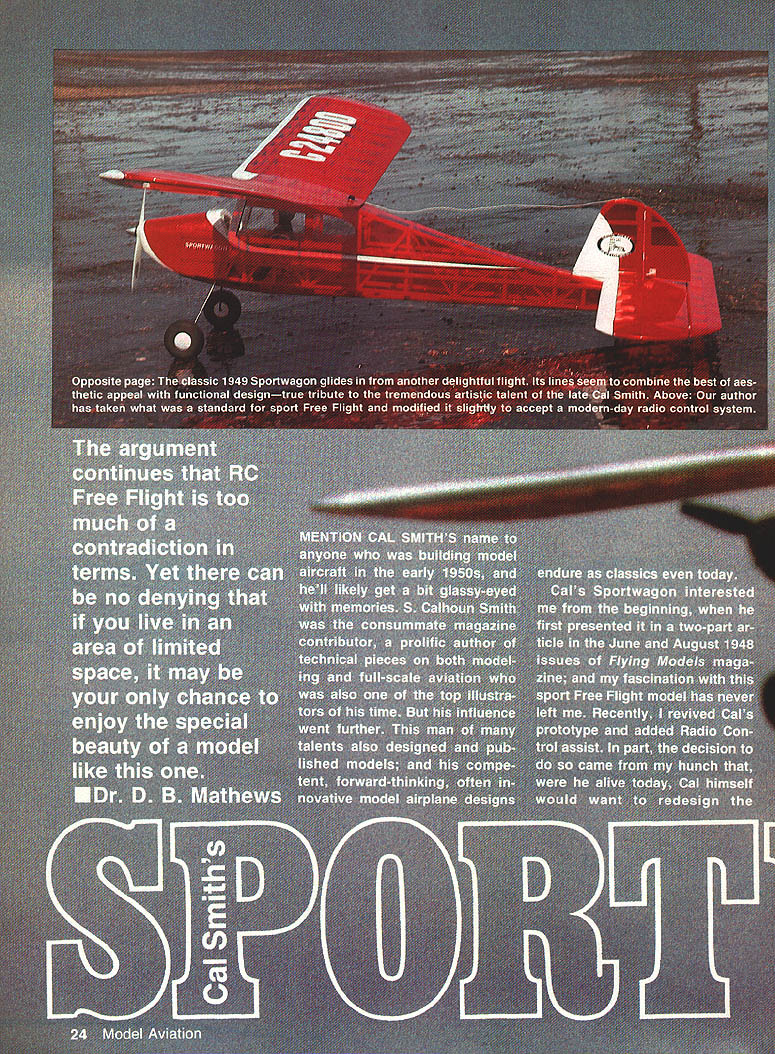
"The argument continues that RC Free Flight is too much of a contradiction in terms. Yet there can be no denying that if you live in an area of limited space, it may be your only chance to enjoy the special beauty of a model like this one." — Dr. D. B. Mathews
Mention Cal Smith's name to anyone who was building model aircraft in the early 1950s and he'll likely get a bit glassy-eyed with memories. S. Calhoun Smith was the consummate magazine contributor: a prolific author of technical pieces on both modeling and full-scale aviation and one of the top illustrators of his time. But his influence went further. Cal also designed and published models; his competent, forward-thinking, often innovative designs endure as classics even today.
Cal's Sportwagon interested me from the beginning when he first presented it in a two-part article in the June and August 1948 issues of Flying Models magazine. My fascination with this sport Free Flight model has never left me. Recently I revived Cal's prototype and added radio-control assist. In part, the decision came from my hunch that, were he alive today, Cal would want to redesign the Sportwagon to take advantage of modern equipment.
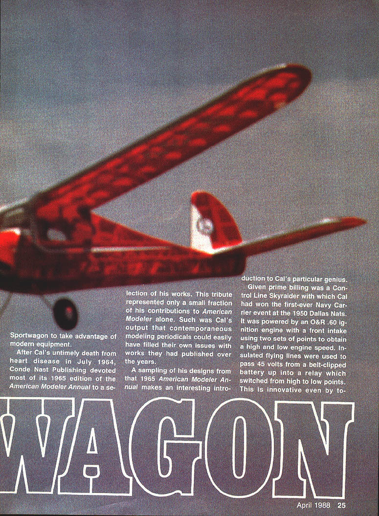
After Cal's untimely death from heart disease in July 1964, Conde Nast Publishing devoted most of its 1965 American Modeler Annual to a selection of his works. This tribute represented only a small fraction of his contributions to American Modeler alone. Such was Cal's output that contemporaneous modeling periodicals could easily have filled issues with works they had published over the years.
A sampling of his designs from that 1965 Annual illustrates Cal's particular genius. Given prime billing was a Control-Line Skyraider with which Cal had won the first-ever Navy Carrier event at the 1950 Dallas Nats. It was powered by an O&R .60 ignition engine with a front intake using two sets of points to obtain high and low engine speeds. Insulated flying lines were used to pass 45 volts from a belt-clipped battery up into a relay which switched from high to low points — innovative even by today's standards.
Other Control-Line subjects included an F-86 Sabre fitted with a Dyna Jet and a four-engined Consolidated B-24; Cal provided cover illustrations for both when they originally appeared. Also shown was his Blunderbus (October 1953 Air Trails), a Free Flight "cutie" designed around the new 1/2A engines of the time. Even this simple model was embellished with Cal's artwork in the form of an isometric drawing of the wire cabane system for the parasol.
Cal was no stranger to R/C airplanes. The Annual included his single-channel K&B .13-powered Monocoupe 90 (January 1955), which even had an optional trike gear. Other R/C designs included the Wonderwings (a biplane), an Aeronca Champ in two-foot scale, a Fokker D-8, and a Sopwith Bipe — the latter one of the very earliest Giant Scale models.
His interest extended to model boats as well. He published designs for a surface submarine, a bunker boat, and a missile ship (the latter in collaboration with Frank Lashek). The Annual spotlighted Cal's Maverick unlimited hydro, including line drawings of the construction and a charcoal illustration of the boat running across a pond with the operator thumbing away on a single-channel transmitter.
Other artworks featured in the Annual were a Meyer's Little Toot and a profile Little Toni, both paired with cover illustrations in the original issues. Cal earned immense distinction as an illustrator. His vivid artwork added a singular dimension to his construction articles, equaled by few either before or since. His brilliant use of subtle color, incredible accuracy, and novel way of expressing movement have seldom been duplicated. Cal's cutaway perspective drawings compare favorably with those of the late Hank Clark. His cover art adorned innumerable magazines, most notably American Aircraft Modeler.
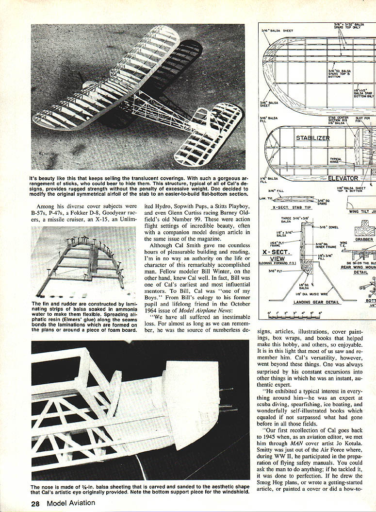
Typical of Cal's models, their beauty sold themselves — translucent coverings with gorgeous stick arrangements could barely hide the structure. His designs provided rugged strength without excessive weight. He often favored techniques such as laminating strips of balsa soaked in ammonia water to make flexible shapes, spreading resin (or Elmer's glue) along seams to bond laminations, and using foam-board patterns for forming parts. The Hydro, Sopwith Pups, Stitts Playboy, Glenn Curtiss racers, and many others combined technical excellence with remarkable beauty.
Although Cal Smith gave countless hours of pleasurable building and reading, I am by no means an authority on his life and character. Fellow modeler Bill Winter knew Cal well and was one of his earliest and most influential mentors. From Bill's eulogy to his former pupil and lifelong friend (Model Airplane News, October 1964):
"We have all suffered an inestimable loss. For almost as long as we can remember, he was the source of numberless designs, articles, illustrations, cover paintings, box wraps, and books that helped make this hobby, and others, so enjoyable. It is in this light that most of us saw and remember him. Cal's versatility, however, went beyond these things. One was always surprised by his constant excursions into other things in which he was, in an instant, an authentic expert.
"He exhibited a typical interest in everything around him—he was an expert at scuba diving, spear-fishing, ice boating, and produced wonderfully self-illustrated books which equaled if not surpassed what had gone before in all those fields.
"Our first recollection of Cal goes back to 1945 when, as an aviation editor, we met him through MAN cover artist Jo Kotula. Smitty was just out of the Air Force where, during WWII, he participated in the preparation of flying safety manuals. You could ask the man to do anything; if he tackled it, it was done to perfection. If he drew the Smo Hog plans, or wrote a getting-started article, or painted a cover or did a how-to sketch, or a model book, or a full-color illustration for Collier's, or a hardcover work for the scholarly book world, or a plastic kit box wrap—the result was above criticism."
More recently, in a letter sent in response to photos of the Sportwagon, Bill put it more incisively: "Cal Smith? God destroyed the mold."
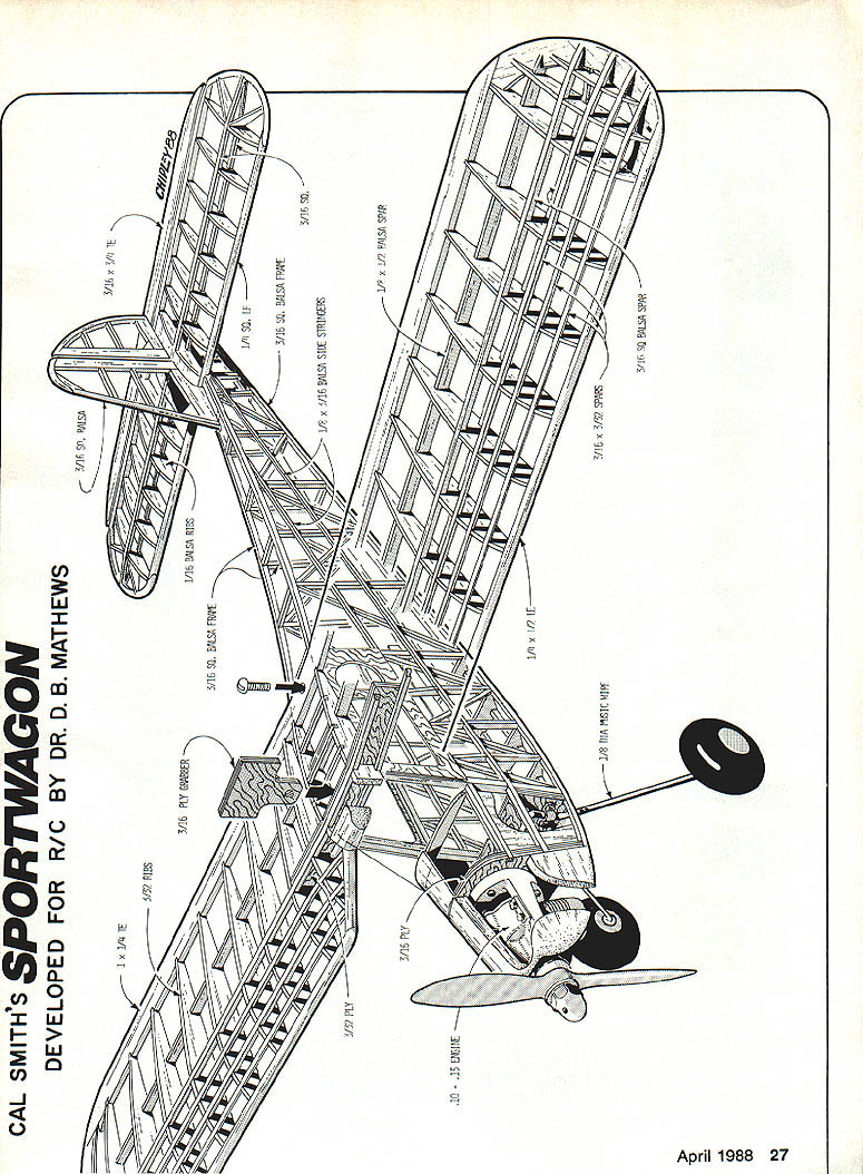
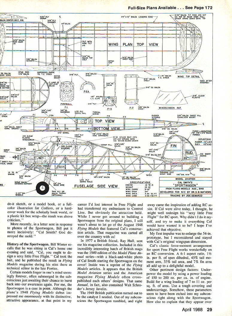
Cal Smith's Sportwagon
Developed for R/C by Dr. D. B. Mathews
History of the Sportwagon
Bill Winter recalls sitting in Cal's home one evening and saying, "Cal, you ought to design a sexy little Free Flight." Cal took the bait and published the result in Flying Models magazine during his stint there as technical editor in the late 1940s.
Certain models linger in one's mind seemingly forever. For me, the Sportwagon is one of those. Although the plane's 1948 Flying Models debut impressed me with its distinctive, attractive appearance, I had at that point lost interest in Free Flight and had transferred my enthusiasm to Control Line. Still, the attraction remained. I never built a Sportwagon from the original plans, but I kept that August 1948 Flying Models issue with me for years.
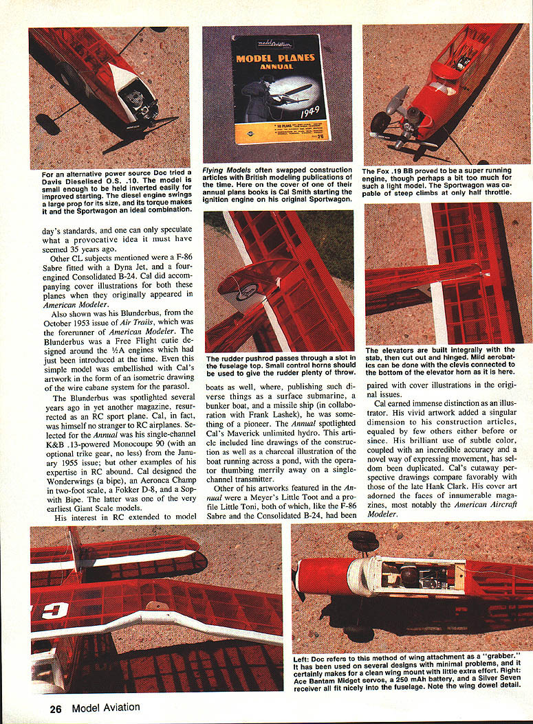
In 1977 a British friend, Ray Hull, sent me his magazine collection. Included was the 1949 Model Plans Annual with a black-and-white photo of Cal Smith starting the Sportwagon on the cover and a reprint of the Flying Models article. The British Model Aviation series and Flying Models often cross-published each other's designs. That Annual also contained Walt Schrod's Jersey Javelin.
The 1949 British publication was the catalyst I needed. The Sportwagon tumbled out of my subconscious, and I immediately had the idea of adding R/C assist. If Cal were alive today, I thought, he might well redesign his "sexy little Free Flight" for R/C sport. Why not try to make it everything Cal would have wanted? I hope I have achieved that objective.
My first impulse was to enlarge the 54-in. prototype, but I stayed with Cal's original wingspan. Cal's classic force-moment arrangement for sport Free Flight works wonderfully on an R/C conversion. The basic proportions are delightful.
Design parameters
- Aspect ratio: 6:1
- Thickness: 1-1/2 in. per ft. of wingspan
- Tail moment arm: 45%
- Tail area: 33% (of wing area)
- Fin area: 7% (of wing area)
- Power loading: underpower the model using 50 to 200 oz. per cu. in. of engine
- Wing loading: 7 to 11 oz. per sq. ft. of area
- Add a touch of reflex in the rear part of the undercamber
Cal powered his prototype with a Bantam .19 on ignition, but he had also been known to use a Forster .29. The British Annual suggested engines such as an E.D. Comp Special, a Mills 2.4, an Allbon 2.8, or the "K" Vulture. In my experience a diesel of roughly .15 cu. in. fits Cal's intentions closely.
The RC Sportwagon should appeal to several groups: nostalgia R/C enthusiasts, old-timers who revere the original Sportwagon, or any modeler looking for a "sexy"-looking sport R/C.
Construction (general)
- Adhesives: Cyanoacrylate (CyA) is the primary adhesive throughout. Use aliphatic resin (Sig Bond, etc.) for laminations and five-minute epoxy for plywood joints.
- Materials: All wood is balsa unless otherwise specified; use medium-weight "C" grain. Strip wood should be clear of knots and medium weight. The structure is on the strong side but well stressed and relatively easy to fabricate.
Wing
- Develop a master plywood rib template by tracing onto the wood, placing waxed paper between the wood and the underside of the plans. Use this pattern to tack-cut the ribs, or cut them with a knife using a metal template.
- Construct wing tip segments in the same way and preassemble them before installation. Notch the trailing edge stock with a razor saw or, preferably, with the blade reversed in a jigsaw.
- Taper the rear spar before assembly to provide a reference point for the tip. Build the center section integral with the left panel, making sure that ribs are vertical (in contrast to the tilt of the outboard rib, set with the jig).
- Place 3/8-in. sheet scraps under the leading edge assembly and the building surface. Lay the wings down, working from the spars forward and ensuring correct rib positioning. Trim tip ribs from the master ribs by slicing them from the bottom.
- Leave the center-section leading edge filler sheet uncemented until the panels are joined. Cut the outboard filler to match the incline of the ribs.
- Sand in the dihedral bevel with a block against a table face, then join the panels using five-minute epoxy and clothespins.
- Custom-fit the plywood dihedral brace to each panel by cutting slots through the ribs against the spar faces (hacksaw blades taped together work well). Slide the ply brace into the slots, dry-fit until the proper dihedral is achieved, epoxy the brace in, and pin the panels to a flat board while the epoxy cures.
- Carve and sand the leading edge, tips, and trailing edge to contour. Although Cal covered the leading edge with 1/32 sheeting originally, modern practice may omit that for practicality.
Fuselage
- Standard box-type construction is employed: build one frame over the other using masking tape to prevent sticking. A modern radial mount can substitute for the original breakaway engine beams.
- Assemble formers and bulkheads while the fuselage frames cure. Use carbon paper to transfer patterns and build jig frames directly over the drawings (frames #1–3 and #4).
- Remove the frames and separate them carefully. Sand a bevel into the tail post, then place the right frame over the drawing. Trial-fit and adjust the formers for a snug fit; attach with CyA, making sure they are square in all planes.
- Install the left frame onto the formers, checking alignment with a triangle. I prefer to leave the box on the building surface, jacking up the tail post by exactly one-half the fuselage width. Glue the tail frame in place, then cut crosspieces in pairs using the top view as a guide.
- An alternative is to remove the box and set it directly over the top view, then construct from there. In either case, ensure the tail post is on the midline and the stab seat is level.
- Bend the landing gear over the drawing using large vise-grip pliers and a bench vise. A cutoff wheel is useful. Do not attempt to rebend a mistake; make a new gear. The unit is held to former #3 with nylon clips; predrill former #3 before installing the gear.
- Attach the bottom formers and stringers. Moisten the top sheeting with ammonia water and pull it down over the firewall and former A. Side stringers taper to the rear; filler strips around the windows taper up to the wing seat. CyA the 1/64 ply window frames to the stringers and filler strips.
- Sheet plastic windows are attached to the inside of the frames after the fuselage is covered for a neat, easily installed treatment.
- Attach the wing saddle fillers and dowel with five-minute epoxy. Ensure the dowel is centered and level in both planes.
Joining the wing and fuselage
- Hold the fuselage on its side and fit the wing over the dowel. Check alignment, clamp temporarily, and epoxy the dowel when satisfied. Fillet the joint, then fit the top sheeting and cap strips after the joint cures.
- Install the tail surfaces and control linkages.
- To align the wing, use a "grabber" to hold the wing in position. Use a piece of heavy string pinned to the tail post to check the wing is exactly at right angles to the fuselage: measure from a common point on both tips to the tail post and adjust until even.
- Mark the grabber, epoxy it to the joiner, return the wing to the seat, and recheck with the string. Using a drill the size of your nylon bolt, drill down through the hardwood trailing edge into the underlying hardwood block. Screw the bolt into the pre-tapped block, pull it up against the hardwood wing saddle, and secure with CyA.
- A tapped hole and bolt can be used instead, but the rear saddle would probably need thicker hardwood. Cal's original rubber-band wing hold-on technique may allow the wing to slide rearward; a forward dowel from the grabber dowel might help.
Empennage
- Cal originally used a symmetrical stabilizer section. For simplicity I used a flat-bottom section and a flat fin-rudder assembly without an airfoil.
- Make laminated outlines by moistening balsa strips with ammonia water and spreading aliphatic resin along seams. Form these laminations over the plans using pins or over foam board patterns.
- Horizontal stabilizer ribs are constructed like wing ribs: lay the sheet center section, then add spars, ribs, and leading and trailing edges. Use a straightedge to mark and cut 3/16-in. slots in the ribs for the two hinge-line spars. CyA them in place, trim for the tips, and install.
- Use a sanding block to contour hinge spars to match ribs. Add the top center-section sheeting, allowing the fin slot. After final sanding, separate the elevator portion and cut slots for the hinges; do not install hinges permanently yet.
- CyA the elevator horn screw plate to the lite-ply base (it will be under the covering). Fin construction is straightforward.
Installing the hardware
- I chose inverted engine mounting, but upright or sidewinder positions are possible; tank position varies accordingly. I used a small 2-oz. Perfect Brand metal tank, replumbed for rear pickup and top vent. A small Sullivan RC tank will also fit.
- The throttle cable can be enclosed in a nylon rod. Place the battery alongside the tank and as far forward as possible. A Du-Bro switch mount can be positioned on a scrap filler.
- I used 4 x 1/4-in. balsa pushrods with EZ connectors on one servo arm; on the other, threaded wire and a clevis. Nylon rods are an option; note that the rudder exit is on top of the fuselage.
- Balance the Sportwagon at the center of gravity shown on the plan. We required no ballast, but other engine-and-equipment combinations may necessitate nose or tail ballast. Check for free movement of all controls and set up proper control throws.
Covering and finish
- Original covering: silkspan and dope. Modern alternatives: lightweight iron-on fabrics or transparent MonoKote for convenience and durability.
- I used transparent MonoKote with a light Poly-U trim sprayed over it. A light rubbing with 000-grade steel wool adds adhesion. I prefer Sig Stripe Rite for masking and pin stripes, and Sig clear Skybrite to prevent bleed-through. Letters can be vinyl stick-ons from an office supply store.
- Banner wheels, as used on the prototype, add appearance points.
- Hinge recommendation: Klett or Sig pinned hinges. To safeguard them, drill a hole and insert a small piece of toothpick, securing with CyA.
- I covered the Sportwagon with the R/C equipment in place — simpler and easier in practice.
- Cut window holes out of the shrunken MonoKote, cut the window plastic to the outline on the plans, and secure the windows inside the frame with Wyandotte RC 56 adhesive. The windscreen may need slight trimming for a good fit; position it inside the ply at the rear and onto tiny cut-outs in the MonoKote. Use Stripe Rite tape for neat joints.
- Prime the tank and engine compartments with Skybrite and paint with Poly-U.
Flying notes
- This incarnation is R/C-assisted Free Flight — a "sexy little Free Flight." Point her nose into the wind, advance the power, and up and away she goes. The radio is used for slight course corrections and small elevator changes to adjust climb rate or to prevent soaring too high; otherwise she flies merrily on her own.
- If you prefer more active flying, the Sportwagon will accept maneuvers such as stall turns and lazy loops when properly trimmed. The model has excellent stability — Cal did his homework well.
- Begin flight tests with low rates and light power, trimming carefully. Increase power gradually and only after trimming is satisfactory.
Men with Cal Smith's extraordinary gifts and energy do not come along often. Artist, author, and model designer, Cal was a sort of Renaissance man of model aviation. In closing his 1969 tribute in Model Airplane News, Bill Winter declared, "Forgotten, Cal will never be." I hope that updating his Sportwagon will help keep the memory of its designer alive.
Transcribed from original scans by AI. Minor OCR errors may remain.

