
Callisto
John Rimmer
GREEK MYTHOLOGY tells us that Callisto was a beautiful nymph loved by Zeus (Ruler of the Heavens) and placed in the sky as the constellation Ursa Major. The Latin meaning of the word is "beautiful." The Callisto can poetically be termed a beautiful, heavenly lady.
I believe you will find her to be as functionally sound as she is aesthetically pleasing to the eye. But, with all this raving, how do you judge fact from fiction?
The average sailplane enthusiast would have no trouble listing the more important characteristics expected of the "perfect sailplane." These would be: 1) Steep climb to a very high launch altitude—practically hands off and no tip stall; 2) Very low wing loading, around 5 oz./ft.2 for minimum sink rate; 3) Good L/D for penetration; 4) A safe vertical dive ability to escape the booming thermal or to lose altitude quickly in a two-minute or ten-minute precision flight; 5) Stable, flat turn characteristics for thermal work; 6) Easily controlled, reasonably slow, precise landing approach; 7) A fairly sturdy airframe to withstand the wrath of the Earth gods when they are tempted by an unsuspecting sailplane pilot having a mental lapse.
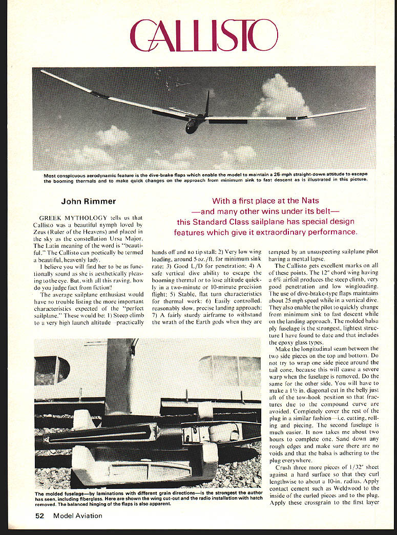
With a first place at the Nats — and many other wins under its belt — this Standard Class sailplane has special design features which give it extraordinary performance.
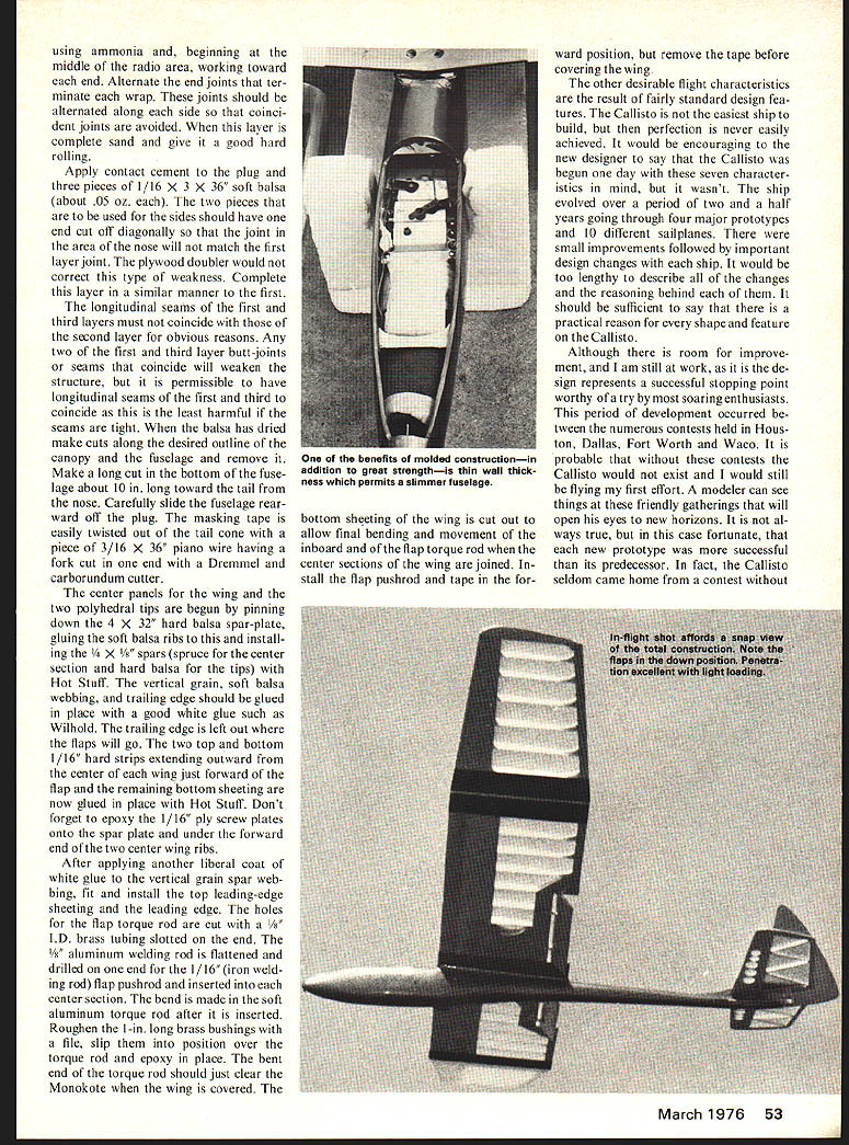
The Callisto gets excellent marks on all of these points. The 12" chord wing having a 6% airfoil produces the steep climb, very good penetration and low wingloading. The use of dive-brake-type flaps maintains about 25 mph speed while in a vertical dive. They also enable the pilot to quickly change from minimum sink to fast descent while on the landing approach. The molded balsa-ply fuselage is the strongest, lightest structure I have found to date and that includes the epoxy-glass types.
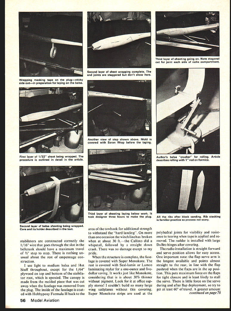
Make the longitudinal seam between the two side pieces on the top and bottom. Do not try to wrap one side piece around the tail cone, because this will cause a severe warp when the fuselage is removed. Do the same for the other side. You will have to make a 1/4" diagonal cut in the belly just aft of the tow-hook position so that fractures due to the compound curve are avoided. Completely cover the rest of the plug in a similar fashion—i.e., cutting, rolling and piecing. The second fuselage is much easier. It now takes me about two hours to complete one. Sand down rough edges and make sure there are no voids and that the balsa is adhering to the plug everywhere.
Crush three pieces of 1/32" sheet against a hard surface so that they curl lengthwise to about a 10-in. radius. Apply contact cement such as Weldwood to the inside of the curled pieces and to the plug. Apply the crossgrain first layer. Apply contact cement to the plug and three pieces of 1/16" x 3" x 36" soft balsa (about .05 oz. each). The two pieces that are to be used for the sides should have one end cut off diagonally so that the joint in the area of the nose will not match the first layer joint. The plywood doubler would not correct this type of weakness. Complete this layer in a similar manner to the first.
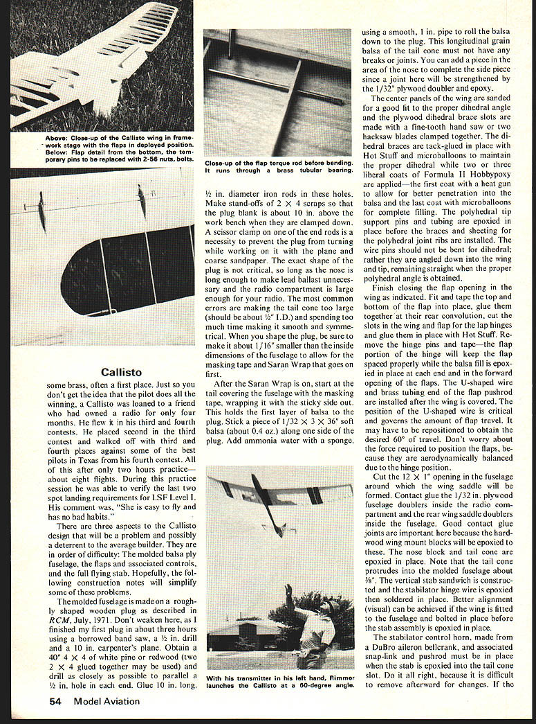
The longitudinal seams of the first and third layers must not coincide with those of the second layer for obvious reasons. Any two of the first and third layer butt-joints or seams that coincide will weaken the structure, but it is permissible to have longitudinal seams of the first and third coincide as this is the least harmful if the seams are tight. When the balsa has dried make cuts along the desired outline of the canopy and the fuselage and remove it. Make a long cut in the bottom of the fuselage about 10 in. long toward the tail from the nose. Carefully slide the fuselage rearward off the plug. The masking tape is easily twisted out of the tail cone with a piece of 3/16" piano wire having a fork cut end with a Dremel and carborundum cutter.
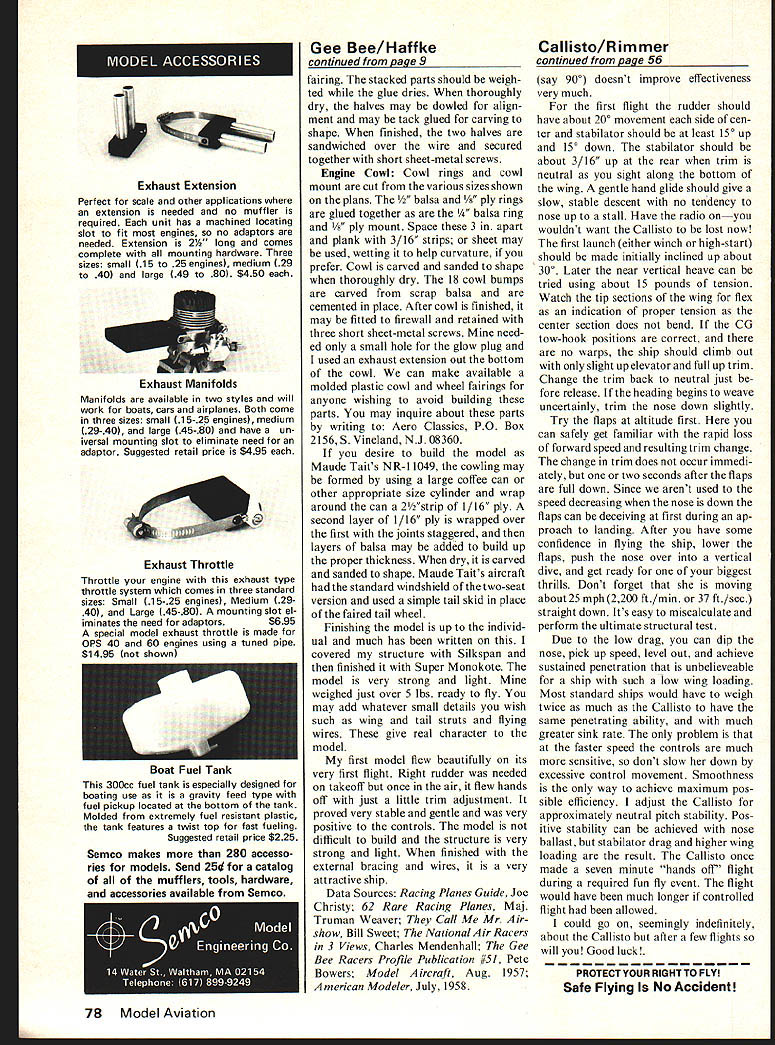
The center panels for the wing and the two polyhedral tips are begun by pinning down the 4" x 32" hard balsa spar-plate, gluing the soft balsa ribs to this and installing the 1/4" x 1/8" spars (spruce for the center section and hard balsa for the tips) with Hot Stuff. The vertical grain, soft balsa webbing, and trailing edge should be glued in place with a good white glue such as Wilhold. The trailing edge is left out where the flaps will go. The two top and bottom 1/16" hard strips extending outward from the center of each wing just forward of the flap and the remaining bottom sheeting are now glued in place with Hot Stuff. Don't forget to epoxy the 1/16" ply screw plates onto the spar plate and under the forward end of the two center wing ribs.
After applying another liberal coat of white glue to the vertical grain spar webbing, fit and install the top leading-edge sheeting and the leading edge. The holes for the flap torque rod are cut with a 1/8" I.D. brass tubing slotted on the end. The 1/8" aluminum welding rod is flattened and drilled on one end for the 1/16" (iron welding rod) flap pushrod and inserted into each center section. The bend is made in the soft aluminum torque rod after it is inserted. Roughen the 1-in. long brass bushings with a file, slip them into position over the torque rod and epoxy in place. The bent end of the torque rod should just clear the Monokote when the wing is covered. The bottom sheeting of the wing is cut out to allow final bending and movement of the inboard end of the flap torque rod when the center sections of the wing are joined. Install the flap pushrod and tape in the forward position, but remove the tape before covering the wing.
The other desirable flight characteristics are the result of fairly standard design features. The Callisto is not the easiest ship to build, but then perfection is never easily achieved. It would be encouraging to the new designer to say that the Callisto was begun one day with these seven characteristics in mind, but it wasn't. The ship evolved over a period of two and a half years going through four major prototypes and 10 different sailplanes. There were small improvements followed by important design changes with each ship. It would be too lengthy to describe all of the changes and the reasoning behind each of them. It should be sufficient to say that there is a practical reason for every shape and feature on the Callisto.
Although there is room for improvement, and I am still at work, as it is the design represents a successful stopping point worthy of a try by most soaring enthusiasts. This period of development occurred between the numerous contests held in Houston, Dallas, Fort Worth and Waco. It is probable that without these contests the Callisto would not exist and I would still be flying my first effort. A modern aeromodeler thanks the friendly gatherings that will open his eyes to new horizons. It is not always true, but in this case fortunate, that each new prototype was more successful than its predecessor. In fact, the Callisto seldom came home from a contest without some brass, often a first place. Just so you don't get the idea that the pilot does all the winning, a Callisto was loaned to a friend who had owned a radio for only four months. He flew it in his third and fourth contests. He placed second in the third contest and walked off with third and fourth places against some of the best pilots in Texas from his fourth contest. All of this after only two hours practice—about eight flights. During this practice session he was able to verify the last two spot landing requirements for LSF Level I. His comment was, "She is easy to fly and has no bad habits."
There are three aspects to the Callisto design that will be a problem and possibly a deterrent to the average builder. They are in order of difficulty. The molded balsa ply fuselage, the flaps and associated controls, and the full flying stab. Hopefully, the following construction notes will simplify some of these problems.
The molded fuselage is made on a roughly shaped wooden plug as described in RCM, July, 1971. Don't weaken here, as I finished my first plug in about three hours using a borrowed band saw, a 1/2 in. drill and a 10 in. carpenter's plane. Obtain a 40" x 4" x 4" white pine or redwood (two 2 x 4 glued together may be used) and drill as closely as possible to parallel a hole in each end. Glue 10 in. long, 1/2 in. diameter iron rods in these holes. Make stand-offs of 2 x 4 scraps so that the plug blank is about 10 in. above the work bench when they are clamped down. A scissor clamp on one of the end rods is a necessity to prevent the plug from turning while working on it with the plane and coarse sandpaper. The exact shape of the plug is not critical, so long as the nose is long enough to make lead ballast unnecessary and the radio compartment is large enough for your radio. The most common errors are making the tail cone too large (should be about 1/2" I.D.) and spending too much time making it smooth and symmetrical. When you shape the plug, be sure to make it about 1/16" smaller than the inside dimensions of the fuselage to allow for the masking tape and Saran Wrap that goes on first.
After the Saran Wrap is on, start at the tail covering the fuselage with the masking tape, wrapping it with the sticky side out. This holds the first layer of balsa to the plug. Stick a piece of 1/32 x 3 x 36 soft balsa (about 0.4 oz.) along one side of the plug. Add ammonia water with a sponge, using a smooth, 1 in. pipe to roll the balsa down to the plug. This longitudinal grain balsa of the tail cone must not have any breaks or joints. You can add a piece in the area of the nose to complete the side piece, since a joint here will be strengthened by the 1/32" plywood doubler and epoxy.
The center panels of the wing are sanded for a good fit to the proper dihedral angle and the plywood dihedral brace slots are made with a fine-tooth hand saw or two hacksaw blades clamped together. The dihedral braces are tack-glued in place with Hot Stuff and microballoons to maintain the proper dihedral while two or three liberal coats of Formula II Hobbyoxy are applied—the first coat with a heat gun to allow for better penetration into the balsa and the last coat with microballoons for complete filling. The polyhedral tip support pins and tubing are epoxied in place before the braces and sheeting for the polyhedral joint ribs are installed.
The wire pins should not be bent for dihedral; rather they are angled down into the wing and tips, remaining straight when the proper polyhedral angle is obtained.
Finish closing the flap opening in the wing as indicated. Fit and tape the top and bottom of the flap into place, glue them together at their rear convolution, cut the slots in the wing and flap for the lap hinges and glue them in place with Hot Stuff. Remove the hinge pins and tape—the flap portion of the hinge will keep the flap spaced properly while the blast fill is epoxied in place at each end and in the forward opening of the flaps. The U-shaped wire bracing and brass tubing in the flap pushrod are installed after the wing is covered. The position of the U-shaped wire is critical and governs the amount of flap travel. It may have to be repositioned to obtain the desired 60° of travel. Don't worry about the force required to position the flaps, because they are aerodynamically balanced due to the hinge position.
Cut the 1/2 x 12 x 1" opening in the fuselage around which the wing saddle will be formed. Contact glue the 1/32 in. plywood fuselage doublers inside the radio compartment and the rear wing saddle doublers inside the fuselage. Good contact glue joints are important here because the hardwood wing mount blocks will be epoxied to these. The nose block and tail cone are epoxied in place. Note that the tail cone protrudes into the molded fuselage about 5/8". The vertical stab sandwich is constructed and the stabilator hinge wire is epoxied in place, then soldered in place. Better alignment (visual) can be achieved if the wing is fitted to the fuselage and bolted in place before the stab assembly is epoxied in place.
The stabilator control horn, made from a DuBro aileron bellcrank, and associated snap-link and pushrod must be in place when the stab is epoxied into the tail cone slot. Do it all right, because it is difficult to remove afterward for changes. If the
Callisto
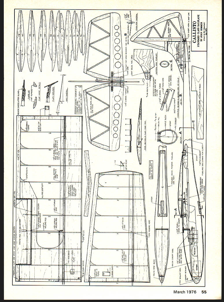
This page contains full-size plans and drawings for the Callisto standard-class sailplane (designer: John Rimmer). There is no running article text on this page — only plan views, part templates, and labels for the model components (wing ribs, fuselage formers, tail cone, radio installation hatch, wing cut-out, molded fuselage notes, etc.). Stabilators are constructed correctly the 1/16" wire that goes through the slot in the bellcrank should have a maximum travel of 1/2" stop to stop. There is nothing unusual about the rest of empennage construction.
I use light to medium balsa and Hot Stuff throughout, except for the 1/64" plywood on top and bottom of the stabilator root, which is epoxied. The canopy is made from the molded piece that was cut away when the fuselage was removed from the plug. The inside of the fuselage is coated with Hobbypoxy Formula II back to the area of the tow hook for additional strength to withstand the "hard landing". On more than one occasion the winch line has broken when at about 30 ft.—the Callisto did a whipsault, followed by a straight down crash. There was no damage except to my pride.
When the structure is complete, the fuselage is covered with Super Monokote. The rest is covered with Seal-lamin or Lamco laminating mylar for a one-ounce and five-dollar saving. It works just like Monokote, considering that it is about 30% thinner without pigment. Look for it at office supply stores; I couldn't build so many large wing sailplanes without this covering. Super Monokote strips are used at the polyhedral joints for visibility and resistance to tearing when tape is applied and removed. The rudder is installed with large DuBro hinges after covering.
The radio installation is straightforward and servo position allows for easy access. One important note: the flap servo arm is the longest available and points almost straight to the rear, in line with the flap pushrod when the flaps are in the up position. This puts maximum force on the flaps for tight closure and is least likely to stall the servo. There is little force on the servo during and after flap deployment, so try to get at least 60° of travel. (say 90°) doesn't improve effectiveness very much.
For the first flight the rudder should have about 20° movement each side of center and stabilator should be at least 15° up and 15° down. The stabilator should be about 3/16" up at the rear when trim is neutral as you sight along the bottom of the wing. A gentle hand glide should give a slow, stable descent with no tendency to nose up to a stall. Have the radio on — you wouldn't want the Callisto to be lost now! The first launch (either winch or high‑start) should be made initially inclined up about 30°. Later the near‑vertical launch can be tried using about 15 pounds of tension. Watch the tip sections of the wing for flex as an indication of proper tension as the center section does not bend. If the CG and two‑hook positions are correct, and there are no warps, the ship should climb out with only slight up elevator and full up trim. Change the trim back to neutral just before release. If the heading begins to weave uncertainly, trim the nose down slightly.
Try the flaps at altitude first. Here you can safely get familiar with the rapid loss of forward speed and resulting trim change. The change in trim does not occur immediately, but a few seconds after the flaps are full down. Since we aren't used to speed decreasing when the nose is down, the flaps can be deceiving at first during an approach to landing. After you have some confidence in flying the ship, lower the flaps, push the nose over into a vertical dive, and get ready for one of your biggest thrills. Don't forget that she is moving about 25 mph (2,200 ft/min, or 37 ft/sec) in a straight down. It is easy to miscalculate and perform the ultimate structural test.
Due to the low drag, you can dip the plane, pick up speed, level out, and achieve sustained penetration that is unbelievable for a ship with such a low wing loading. Most standard ships would have to weigh twice as much as the Callisto to have the same penetrating ability, and with much greater sink rate. The only problem is that at the faster speed the controls are much more sensitive, so don't be nervous about excessive control movement. Smoothness is the only way to achieve maximum possible efficiency. I adjust the Callisto for approximately 90% of model static stability. Positive stability cannot be achieved with nose ballast, but stabilator drag and higher wing loading are the result. The Callisto once made a seven‑minute "hands off" flight during a required fun‑fly event. The flight would have been much longer if controlled by light hand down.
Enjoy her. You'll find the Callisto enormously satisfying after a few flights. Good luck!
Transcribed from original scans by AI. Minor OCR errors may remain.

