
Callisto '82
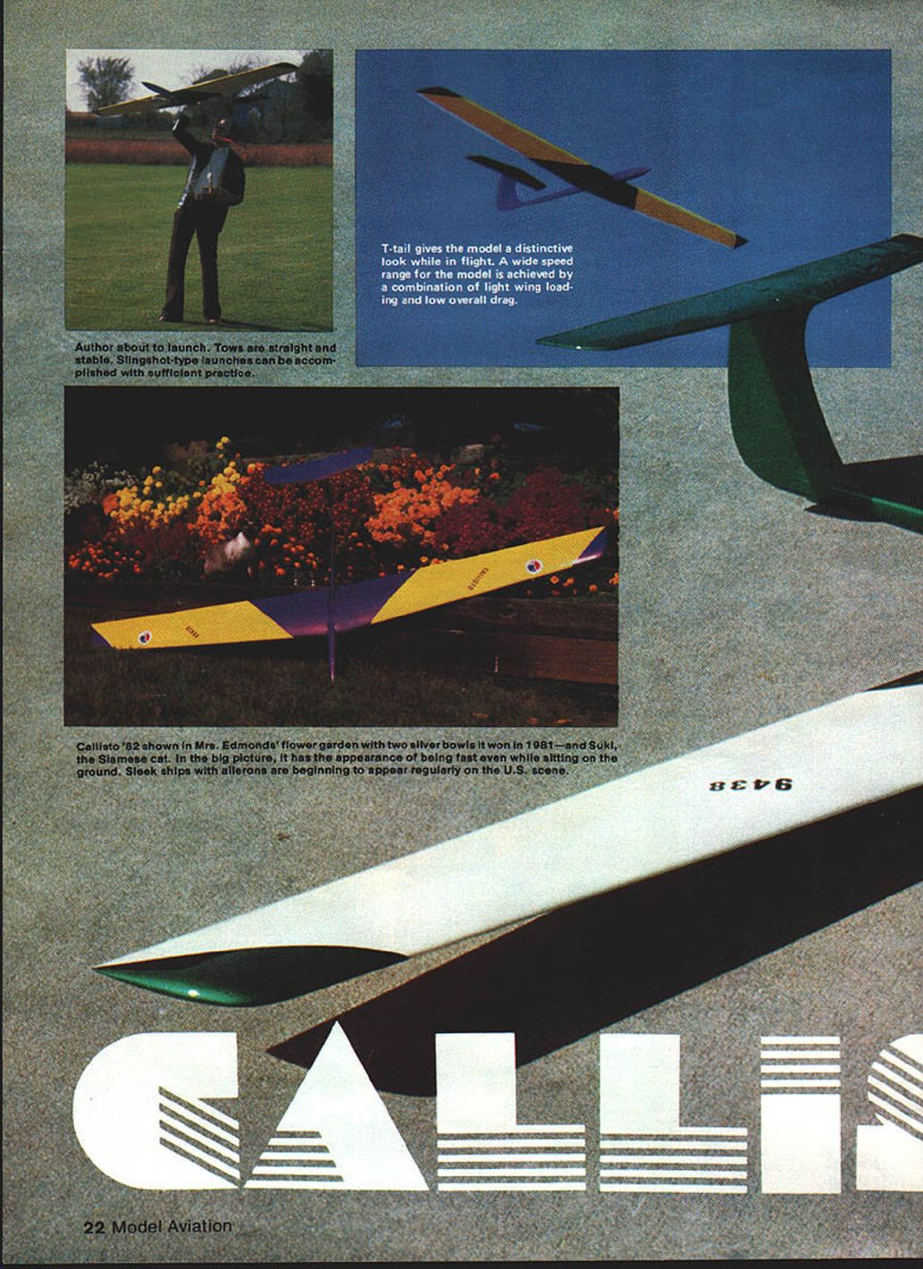
Author about to launch. Tows are straight and stable. Slingshot-type launches can be accomplished with sufficient practice.
T-tail gives the model a distinctive look while in flight. A wide speed range for the model is achieved by a combination of light wing loading and low overall drag.
Callisto '82 shown in Mrs. Edmonds' flower garden with two silver bowls it won in 1981 — and Suki, the Siamese cat. In the big picture, it has the appearance of being fast even while sitting on the ground. Sleek ships with ailerons are beginning to appear regularly on the U.S. scene.
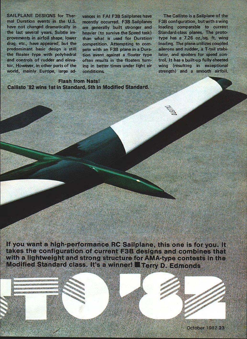
SAILPLANE DESIGNS for Thermal Duration events in the U.S. have not changed dramatically in the last several years. Subtle improvements in airfoil shape and lower drag have appeared, but the predominant basic design is still the floater type with polyhedral and rudder/elevator controls. However, in other parts of the world, mainly Europe, large advances in FAI F3B sailplanes have recently occurred. F3B sailplanes are generally built stronger and heavier (to survive the Speed task) than those used for Duration competition. Attempting to compete with an F3B plane in a Duration event against a floater type often results in the floaters turning in better times under light-air conditions.
Flash from Nats!
Callisto '82 wins 1st in Standard, 5th in Modified Standard.
The Callisto is an F3B-configuration sailplane with wing loading comparable to current Standard-class planes. The prototype has a 7.26 oz./sq. ft. wing loading. The plane utilizes coupled ailerons and rudder, a T-tail stabilator, and spoilers for speed control. It has a built-up fully-sheeted wing (resulting in exceptional strength) and a smooth airfoil.
If you want a high-performance RC sailplane, this one is for you. It takes the configuration of current F3B designs and combines that with a lightweight, strong structure for AMA-type contests in the Modified Standard class. It's a winner! — Terry D. Edmonds
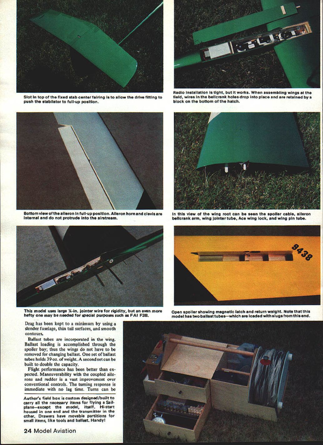
Drag has been kept to a minimum by using a slender fuselage, thin tail surfaces, and smooth contours.
Ballast tubes are incorporated in the wing. Ballast loading is accomplished through the spoiler bay; thus the wings do not have to be removed for changing ballast. One set of ballast tubes holds approximately 3.9 oz. of weight. A second set can be built to double the capacity.
Flight performance has been better than expected. Maneuverability with the coupled ailerons and rudder is a vast improvement over conventional controls. The turning response is immediate with no lag time. Conventional spoiler-type control response is also useful for thermal hunting and spot landings.
Author's field box is custom designed/built to carry all the necessary items for flying a sailplane—except the model itself. Hi-start is housed in one end and the transmitter in the other. Drawers have movable partitions for small items, like tools and ballast. Handy!
Radio installation and wing assembly
Radio installation is tight when assembling the wings. Field wires and bellcrank holes drop into place and are retained by a block under the bottom hatch. Bottom view shows the aileron in the full-up position. The aileron horn clevis is internal and does not protrude into the airstream. At the wing root can be seen the spoiler cable, aileron bellcrank arm, and wing jointer tube. The wing lock/wing pin tube and open spoiler showing magnetic latch and return weight are provided.
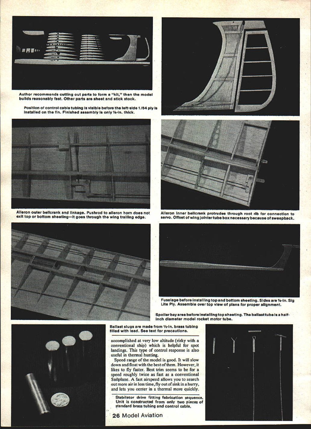
Note: The model has two ballast tubes which are loaded with slugs. The ballast tube is a 1/2-inch diameter model rocket motor tube. Ballast slugs are made from 1/4-inch brass tubing filled with lead. See text for precautions — working with molten lead is hazardous. Accomplished very low-altitude work is risky.
The speed range of the model is good. It will slow down and float best; however, it likes to fly faster. Best trim seems to be at a speed roughly twice that of a conventional sailplane. Faster airspeed allows you to search out lift in less time; flying out of sink in a hurry lets you center a thermal quickly.
Stabilator drive fitting fabrication sequence: the unit is constructed of two pieces of brass tubing and control cable.
The author recommends cutting out parts from the kit; the model builds reasonably fast. Other parts are made from sheet and stick stock.
Aileron — outer bellcrank linkage: the pushrod aileron horn exits the top and bottom sheeting; it passes through the wing trailing edge. The aileron bellcrank passes through the root rib to connect to the servo. An offset wing joiner tube/box is necessary because of the wing sweepback.
Fuselage — assemble over the top-view plans for proper alignment. Ballast tubes are positioned in the rear wing sheeting. Position of control cable tubing is visible before the left-side 1/64 ply is installed on the fin. Finished assembly is only 1/4 in. thick.
Spoiler bay area before installing top sheeting. The ballast tube is a half-inch diameter model rocket motor tube.
Ballast slugs are made from 1/4-in. brass tubing filled with lead. See text precautions.
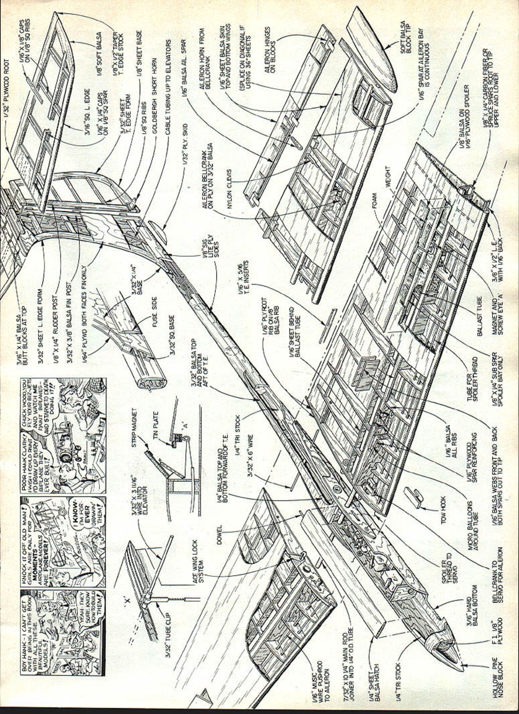
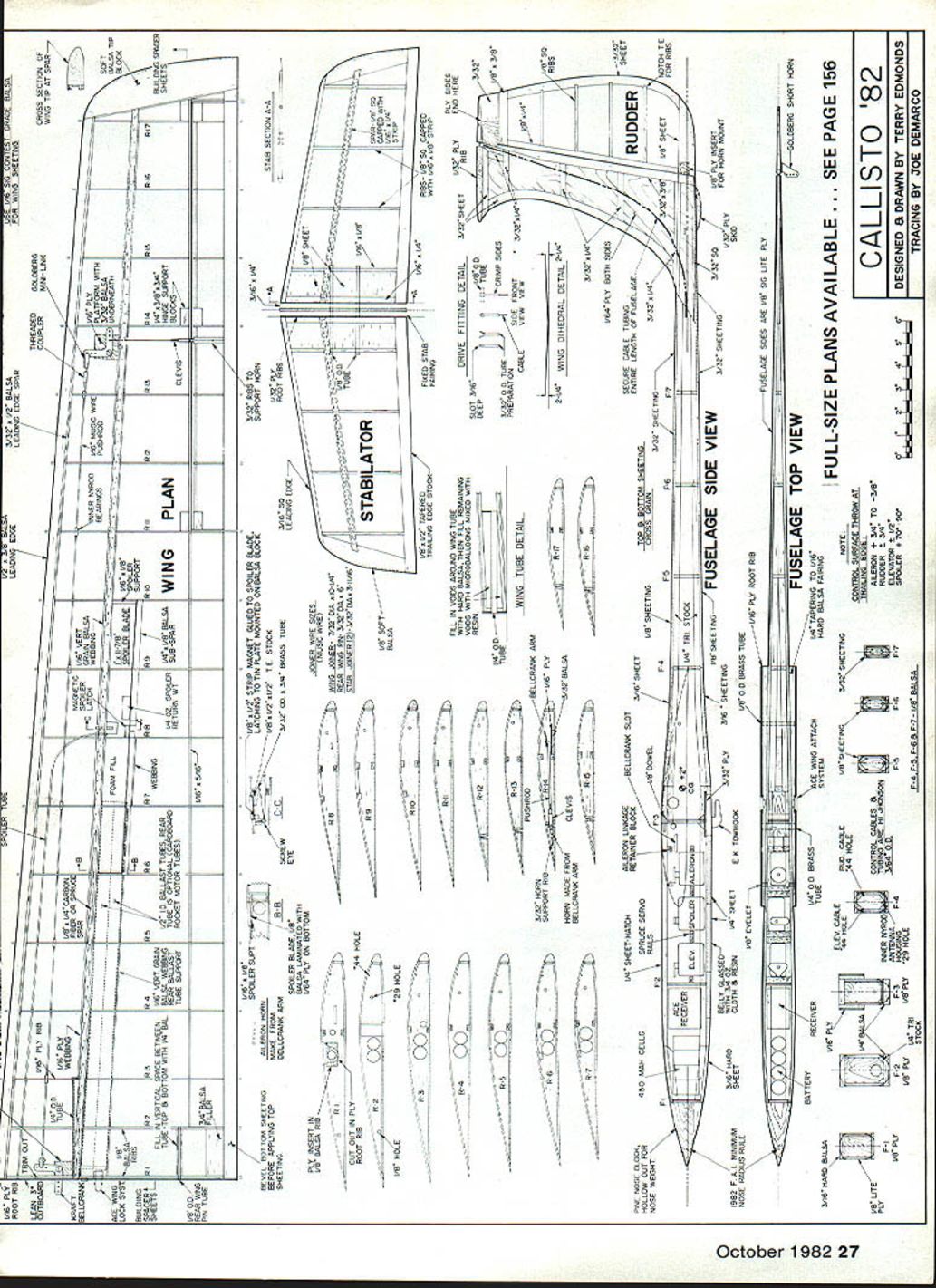
FULL-SIZE PLANS AVAILABLE ... SEE PAGE 156
Designed & drawn by TERRY EDMONDS Tracing by JOE DEMARCO
Ballast is not needed until wind speed rises above approximately 15–20 mph.
Flight handling is somewhat like a Slope-Soarer or a powered plane. It is not a particularly stable aircraft, thus you must fly it all the time. This, in turn, allows the plane to "talk" to you more. The slightest air movement around the ship causes it to wiggle or move in a direction indicating an up- or downdraft.
The prototype has a proven contest record. It won eight first places in Modified Standard and Unlimited classes on the 1981 Midwestern contest circuit. It won first place in the Modified Standard class of a 1981 regional NSS Soar-In. In two contests it put in a perfect score.
Callisto is not a beginner's sailplane either to build or to fly. A modeler who has constructed a couple of sailplane kits can probably handle the construction. Someone who has only flown conventional sailplanes, and not aileroned slope soarers or powered planes, should seek the assistance of a more experienced pilot for the first few flights.
Construction
Proper wood selection is the secret to obtaining a strong but light model. As with any model, use lighter wood for the tail section and heavier wood in the front. Important wood grades will be noted later. Do not build Callisto tail-heavy, as there is not much room for nose weight.
Three general types of adhesives are used: cyanoacrylate (regular and gap-filling), epoxy, and solvent-type contact cement (not water-based). Cyanoacrylates are to be used unless otherwise noted. Wherever epoxy is used to glue brass tubing, roughen the brass surface with sandpaper for better adhesion.
Soft woods are used on all trailing edge surfaces. The degree of thinness of these surfaces is left up to the builder. Knife-edge T.E.s are more efficient aerodynamically, but they are fragile and easily warped. Saturating finished edges with cyanoacrylate glue will harden them somewhat.
The building order is wing, fin-rudder, stabilator, and fuselage. This order is necessary to obtain the proper fit of major components to each other. However, some simultaneous building can be done if desired.
Begin construction by cutting out parts to form the "kit." After doing this, the model builds much faster. Use medium-weight C-grain balsa for the ribs. Cut out lightening holes in the plywood ribs (No. 3). Cut out wing tip blocks from soft balsa. Cut out parts such as wing ribs and fuselage sides in pairs. Match-drill holes in the fuselage sides and appropriate root ribs for wing jointer tubes and spoiler tubes. Follow Ace wing lock directions for match-drilling holes for it. Match-drill holes in stab root rib and fin sides.
Wing
The prototype Callisto has carbon fiber spars. For the model in the construction photos, spruce spars were used due to unavailability of carbon fiber at the time. Carbon fiber spars are recommended if they can be obtained. Build the two wing panels simultaneously if building space permits. Match corresponding left and right wood grain and weight as much as possible.
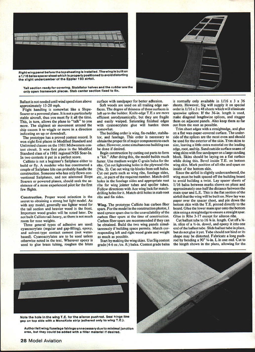
Start by making the wing skins. Use Sig contest grade (4–6 lb/ft³) balsa. Contest grade balsa is normally only available in 1/16 x 3 x 36 in. sheets; Sig will supply 1/16 x 3 x 48 in. sheets on special order to eliminate spanwise splices. If using 36 in. length, make diagonal lengthwise splices and stagger them on adjacent panels. Keep splices as far out from the root as possible.
Trim sheet edges with a straightedge, and glue on a flat wax-paper-covered surface. The underside of the splices are the most even and should be used for the exterior of the skin. Trim skins to size, leaving a little extra material on the leading edge, root, and tip. Sand outside surface seams of wing skins with fine sandpaper on a large sanding block. Skins should be laying on a flat surface while doing this. Bevel inside T.E. on bottom wing skin. Mark position of all ribs and spars on inside of the bottom skin.
Since the airfoil is slightly undercambered, the wing must be built spaced off the building board to avoid building a twist. Lay spacer sheets of 1/16 in. balsa between marks shown on plans and approximately halfway between the main spar and L.E. Lay wax paper over the spacer sheet, and pin down the bottom skin with the T.E. pinned directly to the board. Glue the lower main spar onto the bottom skin using a straightedge to ensure a straight spar. Glue in Ribs 3–17 except for aileron ribs.
Cut ballast tube to 16-1/2 in. length. Cut off a 1/8-in. slice of a 1/2-in. dowel, and epoxy it into one end of the ballast tube. Slide ballast tube in place, but do not glue it yet. Tube should not bind or its shape may be distorted.
Fabricate a long pushrod by bending a 90° 1/4-in. L in one end. Cut to the length shown in the plans, allowing for the addition of a threaded coupler and nylon clevis. Slide on six inner Nyrod bearings, and then solder on a threaded coupler. Slide pushrod and bearings into wing ribs, but do not glue bearings yet. Assemble 3/8-in. ply insert and wing lock into Rib 1 according to Ace instructions.
Make a 93° gauge from scrap balsa for checking the 3° lean angle on Rib 1. Glue on Rib 1 using the gauge and a straightedge. Misalignment here will make it difficult to get a good fit of the wing to the fuselage. Glue in all balsa vertical webbing. Leave spaces shown for aileron pushrod and spoiler horn. Drill a hole in webbing next to Rib 8 for the spoiler tube. Epoxy the plywood webbing in place, except for the forward piece of the wing tube box. Glue ballast tube in place. Relieve the ballast tube in the rear portion of Rib 2 to slide it into place, then glue.
Glue in the rear 1/8 x 1/4 spoiler sub-spar. Glue in the rear ballast tube support webbing. There is also a piece of webbing behind the rear spoiler spar between Ribs 7 and 8 to prevent ballast slugs from rolling back in the wing while changing them.
Cut 3/32-in. T.E. (portion in front of aileron) with a notched exit hole for the aileron clevis, and glue in place. Make pin holes in bottom sheeting to mark cut-out line of aileron. Bevel one edge of the aileron L.E., and glue in place using an aileron rib as a gauge to obtain the proper angle. A 3/32-in. gap should be at the bottom and a 1/64-in. gap at the top. Glue in all aileron ribs and hinge support blocks. Glue 1/16 x 5/16 rear braces between Ribs 2 and 11.
Check the front of the wing ribs for evenness with a straightedge, and trim as necessary. Bevel the bottom edge of 3/32-in. L.E. spar, and glue it on the front of ribs and bottom skin. Temporarily remove wing panels from the building board. Cut to length the jointer tubes and the rear wing pin tubes. Flatten outer ends of 1/8-in. o.d. wing pin tubes to prevent the connecting wire from going too far into the wing.
Prop up the wing panels to the proper dihedral angle, and trial-fit the wing tubes and wiring using 1/16 ply rib joints as gauges. Spacing between L.E. and T.E. of the wing panels should be equal. Correct any misalignment, then glue brass tubes in place with epoxy.
Pin wing panels back on the building board with spacer sheets. Cut triangular spar stock to build offset in the wing tube box, and epoxy in place. Fill the box where possible with small hard balsa sticks. Fill any remaining voids with epoxy mixed with microballoons, then epoxy and clamp the front webbing to finish it. Epoxy 1/8-in. stock blocks below and above the rear wing pin tube. Glue the 3/4-in. rear filler block. String the front of Rib 2 onto the pushrod, and glue it in position. Make bellcrank platforms from 1/16 ply. Mount bearings, then glue on 3/32 balsa to the bottom.
Glue in the outer platform where shown. Bevel the bottom of the inner platform so that the end of the bellcrank protrudes through the center slot at a 90° angle to Rib 1. Connect linkage in the bellcrank holes as shown. This gives proper throw to the aileron. The clevis that connects to the aileron horn should be ground flat on one side to provide better clearance to the bottom skin at the exit hole. It is essential that all linkage moves without resistance but without excess play. Correct any binding in the long pushrod bearings, then glue them in place.
Make aileron horn from nylon bellcrank, but do not epoxy in place until after the aileron is covered and installed. Thread in the spoiler cable tube, and glue it in place. If the tube interferes with the aileron pushrod, glue a small block between the bottom skin and the tube for the required clearance. Glue in the spoiler cable screw eye block and spoiler end supports.
Trim down the top of the L.E. spar, webbing, blocks, etc., that may be protruding above the airfoil contour. Use strips of masking tape to protect the top of the ribs while sanding. Bevel the inside T.E. of top skin to match bottom. Mark position on inside of top skin where all ribs, spars, etc., will contact it.
Apply cement to tops of all ribs, spars, etc., and to inside markings on top wing skin. Use slow-setting epoxy. The epoxy will make a more rigid T.E. Lay wax paper on top of the ribs to keep the skin from sticking until properly aligned. Put the skin in place. Use a long piece of 1/2 x 3/8 balsa as a clamp on top of the T.E., and firmly pin it to the building board. Slide out the wax paper in steps, allowing the skin to adhere. Gently rub the skin with the palm of your hand. When cured, remove the wing panels from the building board.
Glue on the 1/8 x 1/4 leading edge and the pre-cut tip block. Fit the ply root rib in place, but do not glue it yet. Make templates of L.E. at Ribs 9 and 17. Carve L.E. to shape using the templates and ply root rib as guides. Carve the tip block. Sand the entire wing with fine sandpaper.
Cut out ailerons using pinhole markings in the bottom skin as a guide. Attempt to finish with a 1/64-in. gap on the aileron ends and on the top L.E.; there should be a 3/32-in. gap on the bottom L.E. Fill in the gaps with balsa if necessary.
Make a cutout in the top sheeting for the spoiler blade. Construct the spoiler blade by laminating 1/8 balsa to 1/64 ply. Trim the blade to size with a 1/64-in. gap on the edges. Lay the blade in the bay, and sand the top surface to the contour of the airfoil. The spoiler magnet latch assembly, return weight, and horn are installed after the wing is covered and the spoiler is hinged. Cut slots for small Klett aileron hinges, positioning them as close as possible to the top surface of the wing. Do not glue the hinge units until after covering.
Fin and rudder
Pin the 1/64-in. ply fin right side to the building board. Glue the 3/32-in. balsa framework in place. Cut notches in the frame for the stabilator control tubing. Glue both control tubes in place, securing to the fin side.
Fabricate the stabilator drive fitting out of two lengths of brass tubing. Cut a slot of 3/16-in. depth in the 3/32-in. o.d. tube with a cutoff wheel. Bend tabs outward to a U shape while flattening out the curvature. Form tabs to fit around the 3/16-in. o.d. tube. Put in the cable, and crimp the 3/32-in. o.d. tube on the sides to lock in the cable. Solder the assembly, being careful to maintain the correct alignment of the 1/16-in. tube.
Trial-fit the drive fitting in the fin. Be certain that it has adequate clearance for the required movement. Cut an exit notch in the fin left side for the rudder control tubing. Attach the left side of the fin with contact cement. Build the rudder over the plans using 3/8-in. stock, except for the T.E. which uses 3/32 in. Space the T.E. off of the plans with 1/64 ply scraps. Sand the rudder to a tapered shape. Sand the L.E. into a 'V' shape (45° each side). Keep the T.E. of the fin square. Cut slots for small Klett hinges. Attempt to achieve a no-gap fit and still allow for the specified rudder throw. Do not glue hinges until after covering.
Stabilator
Pin down the lower 1/16-in. stock. Cut two 5/16-in. o.d. brass tubes to the full length of both stab halves. Flatten the ends slightly so that the jointer wire will not insert too far. Using a ply root as a spacing gauge, tack-glue the tubes in place. Glue in 3/16-in. square spars and ribs. Attach the 3/16-in. sq. L.E. with 1/32-in. spacer shims underneath. Square off the front of the T.E. pieces, and glue on using 1/16-in. space shims, plus extra shims for the proper T.E. angle. Glue on the tips using 1/16-in. spacer shims. Glue in 1/8-in. center sheeting. Use epoxy for gluing the sheeting next to the brass tubes. Glue on the upper 1/16-in. stock.
Remove the stab panels from the board, and cut the jointer tubes between the stab panels, leaving 1/32 in. of tubes projecting from the root. Fit on the ply root ribs, but don't glue yet. Glue the other two ply root ribs to the 3/16-in. sheet balsa, and cut out the fairing pieces.
Trial-fit the fairing, tubing, etc., on the fin with the stab. Make sure that the stab is perpendicular to the fin and that the fairing is at 0° incidence. Epoxy the fairing and the front brass tube to the fin. Also epoxy the ply root ribs to the stab. Assemble the stab, and check the final alignment before the epoxy cures. Cut out the slot in the fairing for the drive fitting to travel in. Put a small bend in the ends of the jointer wires to keep the stab from sliding off. Carefully sand the stab to the airfoil shape of the ply root ribs.
Fuselage
Bevel the inside rear of the fuselage sides where the fin makes contact. Glue on the 1/4-in. triangular longerons. Taper the longerons at the front and rear as shown on the plans. Cut out a slot in the bottom longerons for the tow hook mounting plate. Glue in bulkheads F4, F5, F6, and F7 on the fuselage right side.
Feed the control cable tubing through the bulkhead holes, and epoxy the fin to the fuselage right side. Glue the stabilator control tube along the entire length of the right side. Glue in the antenna housing. Trial-fit the left side, trimming as necessary. The area where the rear longerons meet must be a good fit for rigidity.
Glue fuselage sides together, including F1, F2, F3, and the tow hook mount; use slow-cure epoxy. The rudder control tube should also be glued to the left side. Align the fuselage over the plans (vertical view) and fasten down at the flat bottom section under the radio compartment. Carefully adjust the positioning to obtain a straight fuselage. Use a square to ensure that the fin is perpendicular to the building board.
Glue the small triangular braces on the tow hook mount. Taper the bottom of the nylon tow hook block as shown, and bolt it in place. Cut out the top and bottom cross-grain sheeting pieces. Any misalignment of the vertical fin can be corrected by twisting in the opposite direction while the sheeting is being glued on.
Hatch and pin assembly should be fitted to the rear block before attaching to the fuselage. Note that the balsa is not cross-grained. Sand edges of the sheeting flush with the sides. Hollow out the pine nose block, and epoxy it on. Taper the 1/4-in. sheet wing fairing pieces so that they are approximately 1/16 in. thick at the L.E. and 1/4 in. at the T.E.
Trial-fit the wing with all of the ply root ribs, tubing, etc. By careful trimming of pieces, a tight fit of the wing to the fairing can be achieved.
Make two blocks 2 x 1 in. that are true and of equal height. Set the plane on the blocks positioned on each side of the fuselage. If the incidence of the two wing panels is equal, the root ribs will sit evenly on the blocks. Also check the alignment of the wing to the stab.
When satisfied with the fit of the wing, glue the fairings, tubing, and root ribs to the fuselage with slow-cure epoxy. Reassemble the wings for an alignment check; allow the glue to cure. Using slow-cure epoxy, glue the ply root ribs to the wing root; again assemble the wings on the fuselage and make a final check of the fit to the shape shown. Ply laminations on the fuselage side can be used to check the consistency of rounding. After final sanding, cover the belly with 4-oz. fiberglass cloth and resin. Attach the tail skid and the spoiler cable eyelets.
Covering
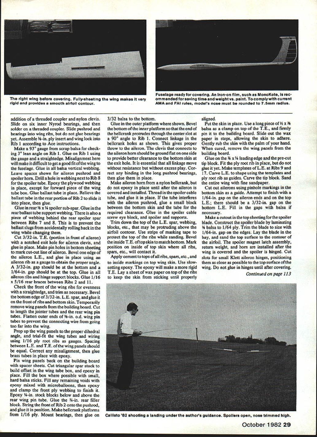
MonoKote was used for covering the entire ship. The fuselage is not difficult to cover with this material. Other finishing methods can be used, but watch the weight. Covering of the stab and rudder must be done with care, as they are easily warped. Shrinking of the covering on both sides simultaneously helps. The spoilers are hinged with a MonoKote strip. A strip of MonoKote is also used to cover the gap on the top of the ailerons. Adhere only on the wing T.E. and not on the aileron. This allows the aileron to move freely and still have the gap covered.
Radio installation
Callisto has a tight radio compartment. The radio will have to be installed very close to the way it is shown. The battery pack is made up of 450 mAh cells taped together. The linkage between the aileron servos and the bellcranks is a section of 1/16-in. music wire with a 90° bend in it. When assembling the wings, ensure the aileron pushrods and bellcranks are correctly aligned and that the aileron horn exits through the wing trailing edge as shown on the plans. The aileron bellcrank protrudes through the root rib to the servo connection. An offset wing jointer tube box is necessary because of the sweepback.
Stabilator drive fitting: fabricate from two pieces of standard brass tubing and the control cable. Assemble and solder or epoxy per the plans. Trial-fit the drive fitting in the fairing and check for full travel with the stab in both neutral and full-up positions.
Simply drop the wire end in the bellcrank hole. A block on the hatch bottom keeps the wire in place. The attachment point of the wire to the servos determines the aileron differential throw. The correct place is near the 45° arc of the servo wheel. The right wing spoiler cable is threaded through a screw eye so that the spoiler throw is equal. Adjust all control surface throws to those indicated on the plans.
Ballast
Ballast is made of 2-in. lengths of 1/4-in. o.d. brass tubing filled with lead (yielding about 2.44 oz. per slug). Molten lead gives off deadly fumes; if you don't know how to handle it, don't attempt it. An alternative would be to epoxy lead shot in the tubes, but only about half the weight will be obtained. When using ballast, fill up the remaining space in the ballast tubes with 2-in. wood dowel pieces and retain with a stiff piece of foam in the spoiler bay.
Flight performance and flying
Flight performance has been better than expected. Maneuverability with coupled ailerons and rudder is a vast improvement over conventional controls; turning response is immediate with no lag time. The Callisto will fly on a hi-start and is housed in the field box along with the transmitter. Ballast tubes are incorporated in the wing, and ballast loading is accomplished through the spoiler bay so the wings need not be removed when changing ballast.
Speed range is good; the model will slow down and float well, but it also likes to fly faster. Best trim seems to be at a speed roughly twice that of a conventional sailplane. Fast airspeed allows you to search out lift in less time, fly out of sink, and quickly center a thermal.
Balance the model where shown on the plan, and balance laterally as well. The front of the hatch is held down with Scotch Tape — not the most ingenious way, but it works well.
Start with the tow hook position on the plans. It can be moved back later on. Try a few hand glides to get the feel of the ship.
If you are uncomfortable with the handling of Callisto at this point, get help before putting it on the line. Callisto climbs straight on the line without any corrections. The wings are very strong and will withstand a tremendous amount of tension. It can, in fact, be slingshotted off the top of the line; the wing rod will bend before the wings fail. If this maneuver is to be used regularly, build wings to accommodate a 1/4-in. dia. jointer wire.
Specifications
- Wingspan: 99½ in.
- Wing Root Chord: 10½ in.
- Wing Tip Chord: 6½ in.
- Total Wing Area: 843 sq. in.
- Wing Airfoil: Eppler 193
- Fuselage Length: 46½ in.
- Stabilator Span: 23 in.
- Stabilator Chord (Average): 4½ in.
- Stab Airfoil: Symmetrical
- Controls: Coupled aileron, rudder, elevator, spoilers
- Weight Ready to Fly: 42.5 oz.
- Wing Loading: 7.26 oz./sq. ft.
Transcribed from original scans by AI. Minor OCR errors may remain.

