
Cam-Axial Engine
Brayton B. Paul
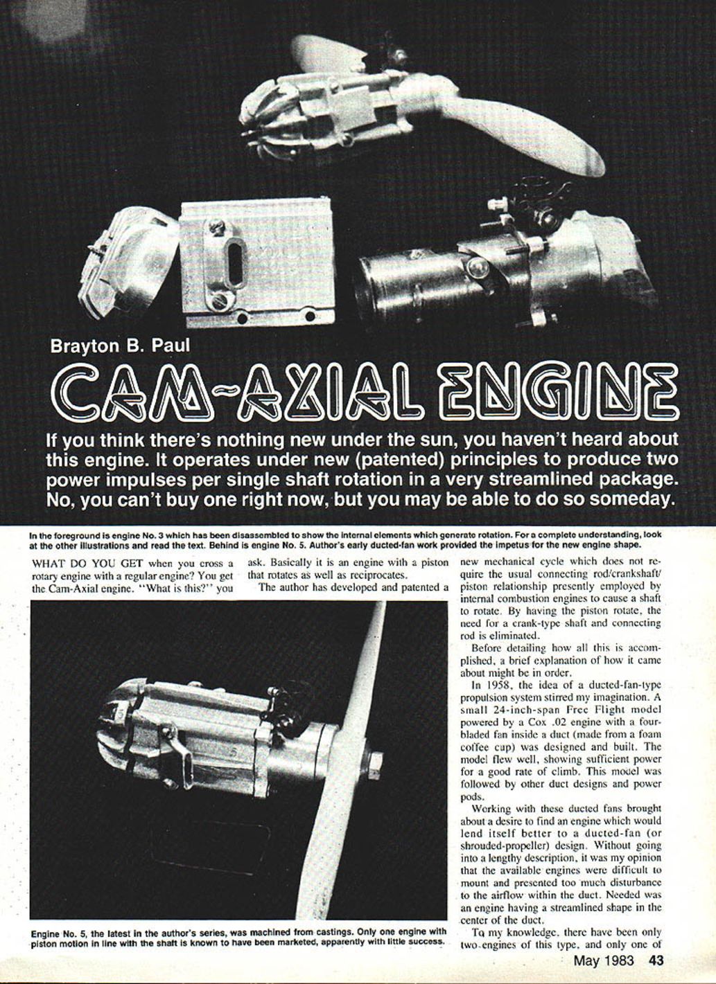
If you think there's nothing new under the sun, you haven't heard about this engine. It operates under new (patented) principles to produce two power impulses per single shaft rotation in a very streamlined package. No, you can't buy one right now, but you may be able to do so someday.
What do you get when you cross a rotary engine with a conventional reciprocating engine? You get the Cam-Axial engine — an engine in which the piston both rotates and reciprocates. The inventor has developed and patented a mechanical cycle that eliminates the usual connecting rod/crankshaft/piston relationship by having the piston rotate; this removes the need for a crank-type shaft and connecting rod.
Background
In 1958 the idea of a ducted-fan propulsion system stirred my imagination. I built a small free-flight model with a 24-inch span, powered by a Cox .02 engine driving a four-bladed fan inside a duct made from a foam coffee cup. The model flew well, showing sufficient power for a good climb rate. That led to further duct designs and power pods.
Working on ducted fans made me want an engine better suited to a shrouded-propeller installation. Existing engines were awkward to mount and disrupted the airflow in the duct; I wanted a streamlined engine in the duct's center. A brick-type plastic model gave proportions and ideas that encouraged further development.
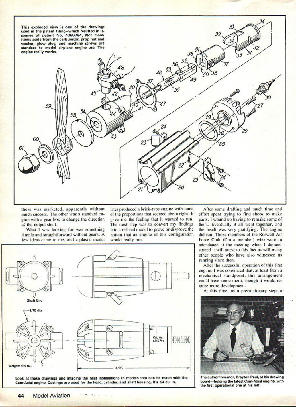
I consulted a patent attorney, and U.S. Patent No. 4,366,784 was issued. While the application was being processed, I pursued improvements, made patterns for the cylinder, head, and shaft housing, and arranged for two sets of aluminum castings. From another plastic model I learned enough to machine the parts myself.
I obtained a used Atlas lathe, a small Sears lathe, and an old drill press. The most difficult part was planning and executing the machining operations to avoid ruining castings; various small tools, fixtures, and setups had to be made. After much work and several remakes of parts, the engine was assembled and did run — witnessed by members of the Roswell Air Force Club and others. The successful operation convinced me the arrangement had mechanical merit, though further development would be needed.
How the engine works
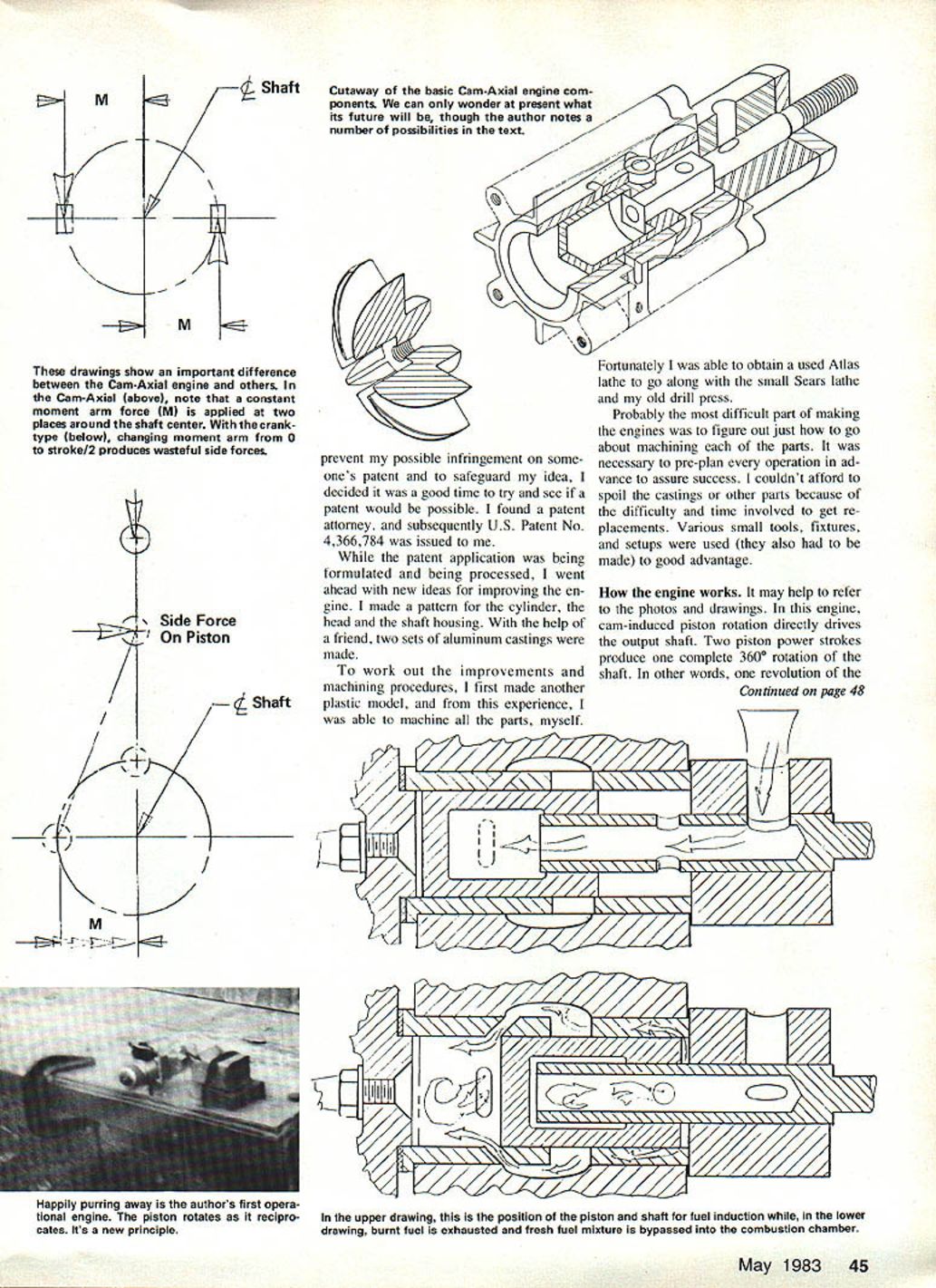
It helps to refer to photos and drawings, but the principle is straightforward. Cam-induced piston rotation directly drives the output shaft. Two piston power strokes produce one complete 360° rotation of the shaft — equivalent to one revolution of a two-cylinder conventional engine. Axial motion of the piston is not transmitted to the output shaft; instead it permits simple and effective fuel-air induction and exhaust similar to many two-stroke engines.
Basic components of the Cam-Axial engine:
- Cylinder and head
- Shaft housing
- Cam-track liner
- Piston with two cam followers (rollers)
- Output shaft
- Exhaust stacks
- Carburetor
- Ignition device
- Necessary hardware
For induction, the output shaft is axially bored and has a cross hole that registers with a passage in the housing leading to the carburetor while the piston moves toward the combustion chamber (head end). Bypass and exhaust ports in the liner and cylinder register and are uncovered when the piston nears its position away from the combustion chamber.
In this model the non-reciprocating output shaft has a square cross section; the piston has a matching square hole and slides axially on the shaft. As the piston reciprocates, the cam track imparts rotational motion to both piston and shaft.
Sequence of operation:
- As the piston moves toward the head, a partial vacuum in the chamber between the housing and piston draws in the fuel-air mixture. This occurs while the shaft intake port is in registration with the induction passage from the carburetor.
- Continued piston movement toward the head compresses the fuel-air mixture. At the optimum compression and piston position, ignition occurs, pushing the piston away from the head.
- The piston’s cam-following rollers run in the liner’s cam track, causing the piston — and consequently the output shaft — to rotate as the piston moves away from the head.
- As the piston moves toward the housing, both exhaust and bypass ports are uncovered, allowing exhaust venting. Because shaft rotation has taken the induction ports out of registration, the fresh charge drawn in is compressed and pushed up the cam track to be bypassed into the combustion chamber while burned gases are exhausted.
This sequence (induction, compression, power, exhaust) corresponds to a 180° rotation of the output shaft. Two such cycles produce a complete 360° rotation of the shaft — two power strokes per shaft revolution.
The piston has two cam-follower rollers spaced 180° apart, attached near the end opposite the combustion end. The cam track is of sinusoidal configuration, giving a static and rotationally balanced unit and enabling the two power strokes per revolution.
Continued on page 148.
Cam-Axial (continued)
Although these first engines were conceived with model airplane propulsion in mind, other uses are possible. The design does not appear to require new materials or processes, so production could leverage current engine-manufacturing technology.
Possible advantages of the Cam-Axial design include:
- More horsepower per unit weight
- More horsepower per displacement
- Smoother operation (reduced vibration)
- Multi-cylinder configurations not possible with conventional engines
- Reduced side forces on the piston because there is no connecting-rod crank angle
- Twice the power pulses per shaft revolution compared with a single-cylinder conventional engine
- Natural lubrication of the cam track, followers, piston, and shaft
- Less dead volume between piston and housing, improving pumping action
- Cam-track configuration can be non-harmonic (programmable) to apply power over varied portions of the shaft rotation for tailored torque characteristics
Another possibly advantageous difference in torque delivery is illustrated in one of the sketches.
Transcribed from original scans by AI. Minor OCR errors may remain.

