
Candle In The Wind
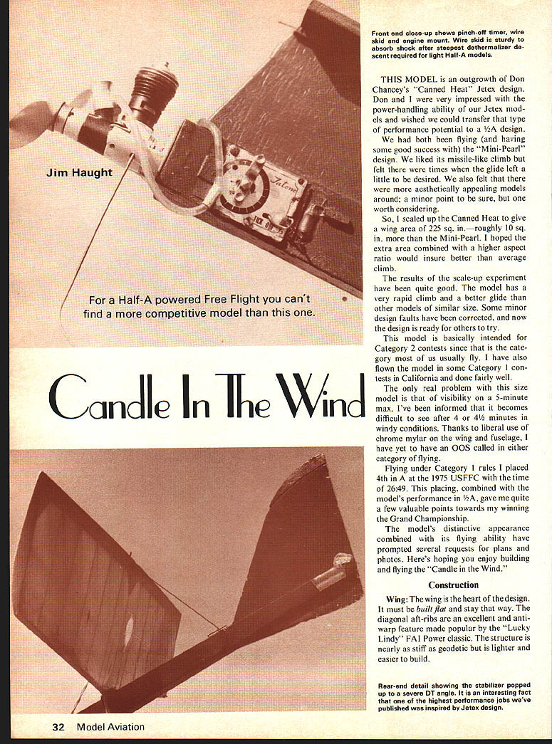
THIS MODEL is an outgrowth of Don Chancey's "Canned Heat" Jetex design. Don and I were very impressed with the power-handling ability of our Jetex models and wished we could transfer that type of performance potential to a 1/2A design.
We had both been flying (and having some good success with) the "Mini-Pearl" design. We liked its missile-like climb but felt there were times when the glide left a little to be desired. We also felt that there were more aesthetically appealing models around; a minor point to be sure, but one worth considering.
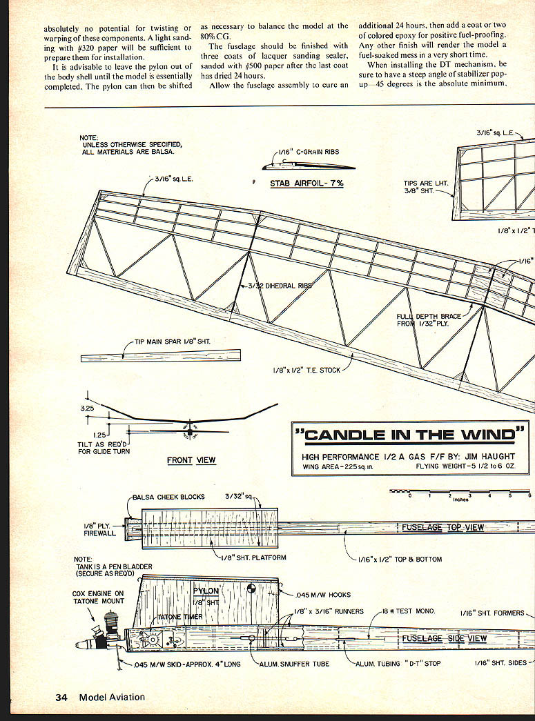
So, I scaled up the Canned Heat to give a wing area of 225 sq. in. — roughly 10 sq. in. more than the Mini-Pearl. I hoped the extra area combined with a higher aspect ratio would insure better than average climb results.
The results of the scale-up experiment have been quite good. The model has a very rapid climb and a better glide than other models of similar size. Some minor design faults have been corrected, and now the design is ready for others to try.
This model is basically intended for Category 2 contests since that is the category most of us usually fly. I have also flown the model in some Category 1 contests in California and done fairly well.
The only real problem with this size model is that of visibility on a 5-minute max. I've been informed that it becomes difficult to see after 4 or 4½ minutes in windy conditions. Thanks to liberal use of chrome mylar on the wing and fuselage, I have yet to have an OOS called in either category of flying.
Flying under Category 1 rules I placed 4th in A at the 1975 USFFC with the time of 26:49. This placing, combined with the model's performance in 1/2A, gave me quite a few valuable points towards my winning the Grand Championship.
The model's distinctive appearance combined with its flying ability have prompted several requests for plans and photos. Here's hoping you enjoy building and flying the "Candle In The Wind."
Construction
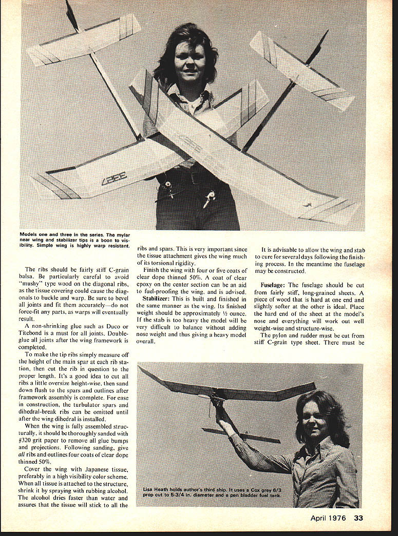
Wing: The wing is the heart of the design. It must be built flat and stay that way. The diagonal aft-ribs are an excellent anti-warp feature made popular by the "Lucky Lindy" FAI Power classic. The structure is nearly as stiff as geodetic but is lighter and easier to build.
The ribs should be fairly stiff C-grain balsa. Be particularly careful to avoid the mushy type wood; diagonal ribs under tissue covering could cause the diagonals to buckle or warp. Be sure to bevel joints and fit accurately; do not force-fit parts — stressed joints will eventually result in warps. Use non-shrinking glue such as Duco or Titebond. Double-glue joints.
After the wing framework is completed, make tip ribs by simply measuring off the height from the main spar rib stations and cutting ribs to the proper length. It's a good idea to cut ribs a little oversize height-wise and sand them down flush to spars and outlines after framework assembly is complete — this will ease construction. Turbulator spars and dihedral-break ribs can be omitted until after wing dihedral is installed.
When the wing is fully assembled structurally, it should be thoroughly sanded with #320 grit paper to remove glue bumps and projections. Following sanding, give ribs and outlines four coats of clear dope thinned 50%. Cover the wing with Japanese tissue, preferably in a high-visibility color scheme. Tissue is attached to the structure by shrinking after spraying with rubbing alcohol. Alcohol dries faster than water and assures the tissue will stick to ribs and spars. This is very important since tissue attachment gives the wing much of its torsional rigidity. Finish the wing with four to five coats of clear dope thinned 50%. A coat of clear epoxy on the center section can aid fuel-proofing if desired.
The stabilizer is built and finished the same manner as the wing. Its finished weight should be kept light; if the stab is too heavy the model will be very difficult to balance, requiring adding nose weight and thus producing an overall heavy model. It is advisable to allow the wing and stab to cure several days following the finishing process. In the meantime the fuselage may be constructed.
Fuselage
The fuselage should be cut from fairly stiff, long-grained sheet balsa. Use a harder end-grain sheet for the nose and a slightly softer sheet elsewhere; placing the hard end at the model's nose will work out well weight-wise and structure-wise. The pylon and rudder must be cut from stiff C-grain sheet.
Fuselage
It is advisable to leave the pylon out of the body shell until the model is essentially completed. The pylon can be shifted as necessary before final installation. as necessary to balance the model at the 80% CG.
The fuselage should be finished with three coats of lacquer sanding sealer, sanded with #500 paper after the last coat has dried 24 hours.
Allow the fuselage assembly to cure an additional 24 hours, then add a coat or two of colored epoxy for positive fuel-proofing. Any other finish will render the model a fuel-soaked mess in a very short time.
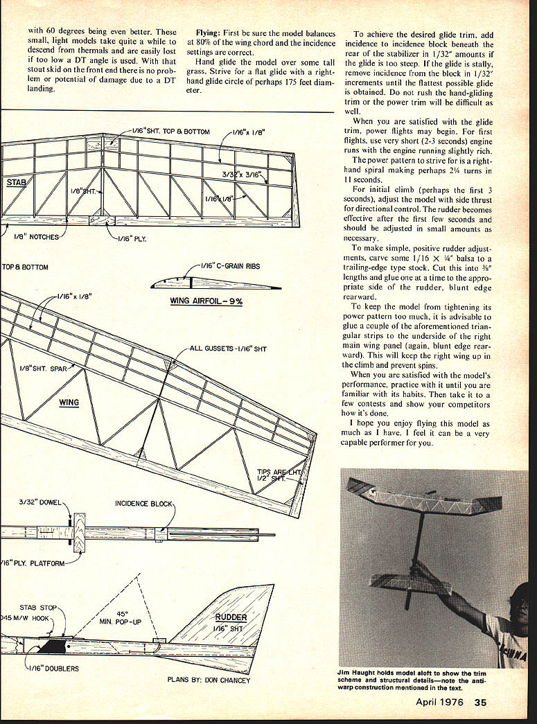
When installing the DT mechanism, be sure to have a steep angle of stabilizer pop-up—45 degrees is the absolute minimum.
Flying
First be sure the model balances at 80% of the wing chord and the incidence settings are correct.
Hand-glide the model over some tall grass. Strive for a flat glide with a right-hand glide circle of perhaps 175 feet diameter.
To achieve the desired glide trim, add incidence to the incidence block beneath the rear of the stabilizer in 1/32" amounts if the glide is too steep. If the glide is stally, remove incidence from the block in 1/32" increments until the flattest possible glide is obtained. Do not rush the hand-gliding trim or the power trim will be difficult as well.
When you are satisfied with the glide trim, power flights may begin. For first flights, use very short (2-3 seconds) engine runs with the engine running slightly rich. The power pattern to strive for is a right-hand spiral making perhaps 2 1/2 turns in 11 seconds.
For initial climb (perhaps the first 3 seconds), adjust the model with side thrust for directional control. The rudder becomes effective after the first few seconds and should be adjusted in small amounts as necessary.
To make simple, positive rudder adjustments, carve some 1/16" x 1/4" balsa to a trailing-edge-type stock. Cut this into 1/8" lengths and glue one at a time to the appropriate side of the rudder, blunt edge rearward.
To keep the model from tightening its power pattern too much, it is advisable to glue a couple of the aforementioned triangular strips to the underside of the right main wing panel (again, blunt edge rearward). This will keep the right wing up in the climb and prevent spins.
When you are satisfied with the model's performance, practice with it until you are familiar with its habits. Then take it to a few contests and show your competitors how it's done.
I hope you enjoy flying this model as much as I have. I feel it can be a very capable performer for you.
Transcribed from original scans by AI. Minor OCR errors may remain.

