
The CAP
Brad Shepherd
Full-scale description
AVIONS MUDRY et Cie — Pour l'art du pilotage: CAP 20. Avion monoplace de voltige et de compétition équipé d'un moteur à injection Avco Lycoming de 200 CV, alimenté et graissé "toutes positions". Construction bois et plastique. Envergure 8.06 m, surface 10.85 m², longueur 7.21 m, à vide 620 kg; facteurs de charge limite en cat. "A": +8 g / -6 g.
I digress — let me return to the beginning of this very satisfying project.
Origins
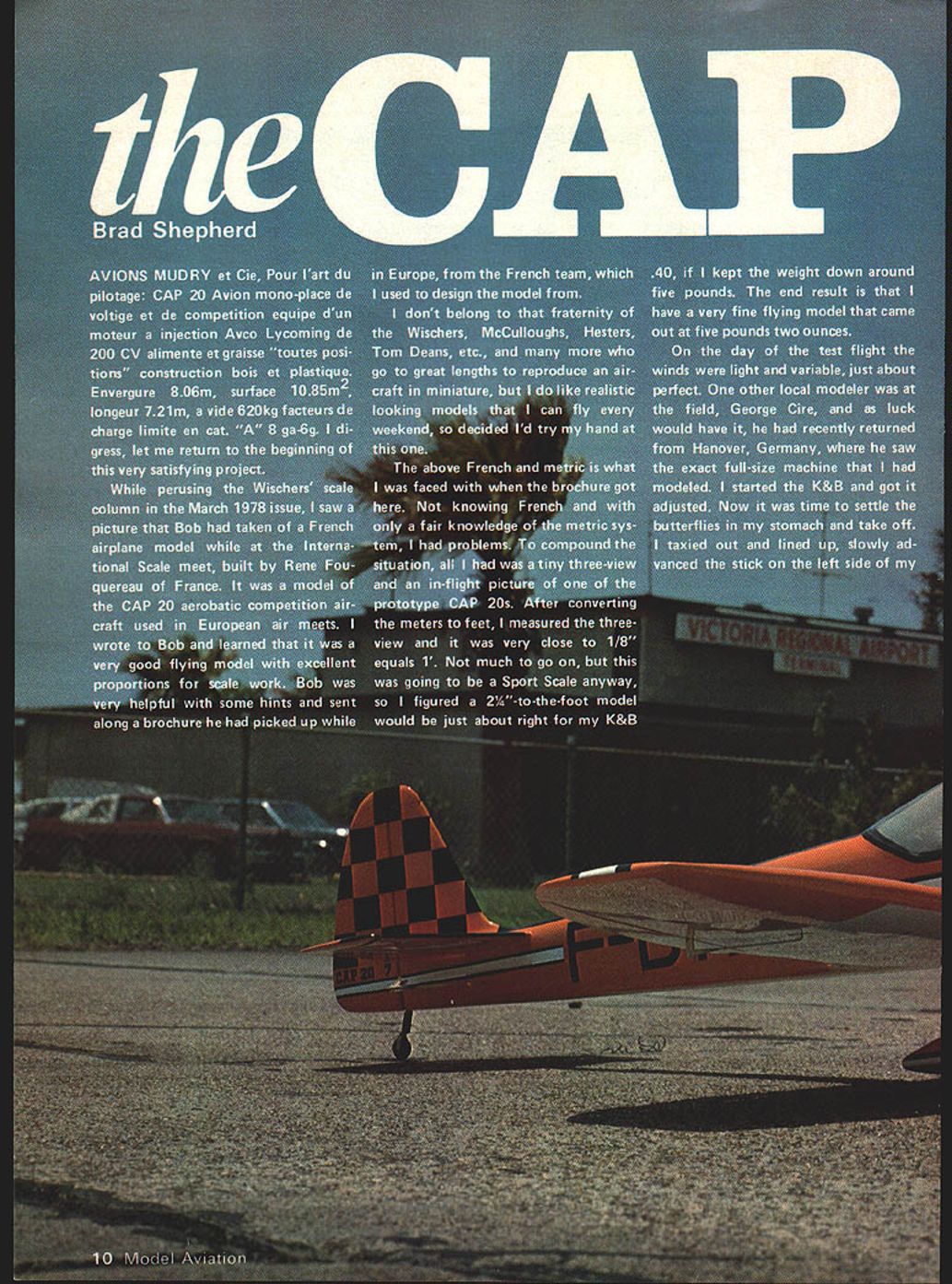
While perusing Bob Wischer's scale column in the March 1978 issue, I saw a picture he had taken of a French airplane model at the International Scale meet, built by René Fouquereau. It was a model of the CAP 20 aerobatic competition aircraft used in European meets. I wrote to Bob and learned it was a very good flying model with excellent proportions for scale work. Bob sent along a brochure he had picked up in Europe from the French team, which I used to design my model.
I don't belong to the fraternity of modelers who go to extreme lengths to reproduce an aircraft in miniature, but I do like realistic-looking models that I can fly every weekend. I decided to try my hand at this one.
The brochure presented French text and metric dimensions. Not knowing French well and only having a fair knowledge of the metric system, I had some problems. All I had was a tiny three-view and an in-flight picture of one of the prototype CAP 20s. After converting meters to feet, I measured the three-view and it came out very close to 1/8" = 1'. Since this was going to be a Sport Scale model, I figured a 2½" to the foot scale would be about right for my K&B .40 engine, if I kept the weight down to around five pounds. The end result: a very fine flying model that weighed 5 lb 2 oz.
First flight
On the day of the test flight the winds were light and variable — just about perfect. Another local modeler, George Cire, happened to be at the field; he had recently returned from Hanover, Germany, where he saw the exact full-size machine I had modeled.
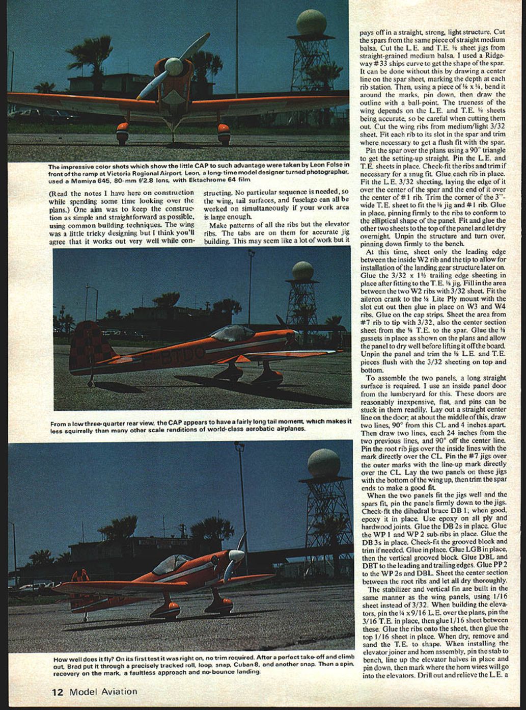
I started the K&B .40 and got it adjusted. I taxied out, lined up, slowly advanced the throttle and fed in a little right rudder. It tracked perfectly straight with the tail up. I eased back on elevator and it climbed in a straight shallow climb, made a 180 and came back over at about 40 feet. No trim adjustments were needed — it was "in the groove." I was elated.
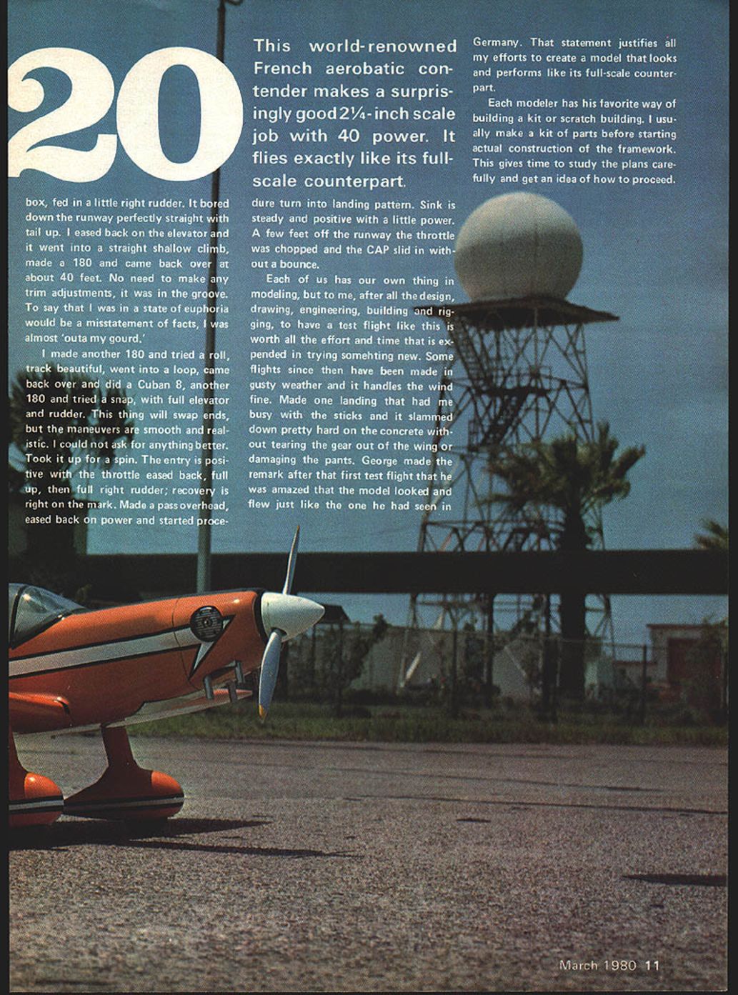
I made another 180 and tried a roll — beautiful tracking — then a loop, a Cuban 8, and a snap with full elevator and rudder. The model will swap ends, but the maneuvers are smooth and realistic. Stall entry is positive with throttle eased back: full up elevator and full right rudder; recovery is right on the mark. I made a pass overhead, eased back on power, started a procedure turn into the landing pattern, and slid it in without a bounce.
Subsequent flights in gusty conditions showed the model handles wind fine. One landing slammed down hard on concrete but did not tear the gear out or damage the pants. George remarked that the model looked and flew just like the one he had seen in Germany — a gratifying endorsement of my efforts.
Building philosophy
Each modeler has their own way of building. I usually make a kit of parts before starting the framework. This gives time to study the plans and plan the build. One aim was to keep the construction simple and straightforward, using common building techniques. The wing was a little tricky to design, but the method works well. No particular sequence is required, so the wing, tail surfaces, and fuselage can be worked on simultaneously if your work area is large enough.
Make patterns of all ribs (except elevator ribs, which have tabs for accurate jigging). This may seem like a lot of work but it pays off with a straight, strong, light structure. Use straight-grained medium balsa for spars and LE/TE jigs. A ships curve helps fair the spar shape, but you can do it by marking rib depths on the spar sheet and drawing the outline with a flexible scrap strip.
Be careful: the trueness of the wing depends on accurate LE and TE 3/32" sheets and correctly cut ribs.
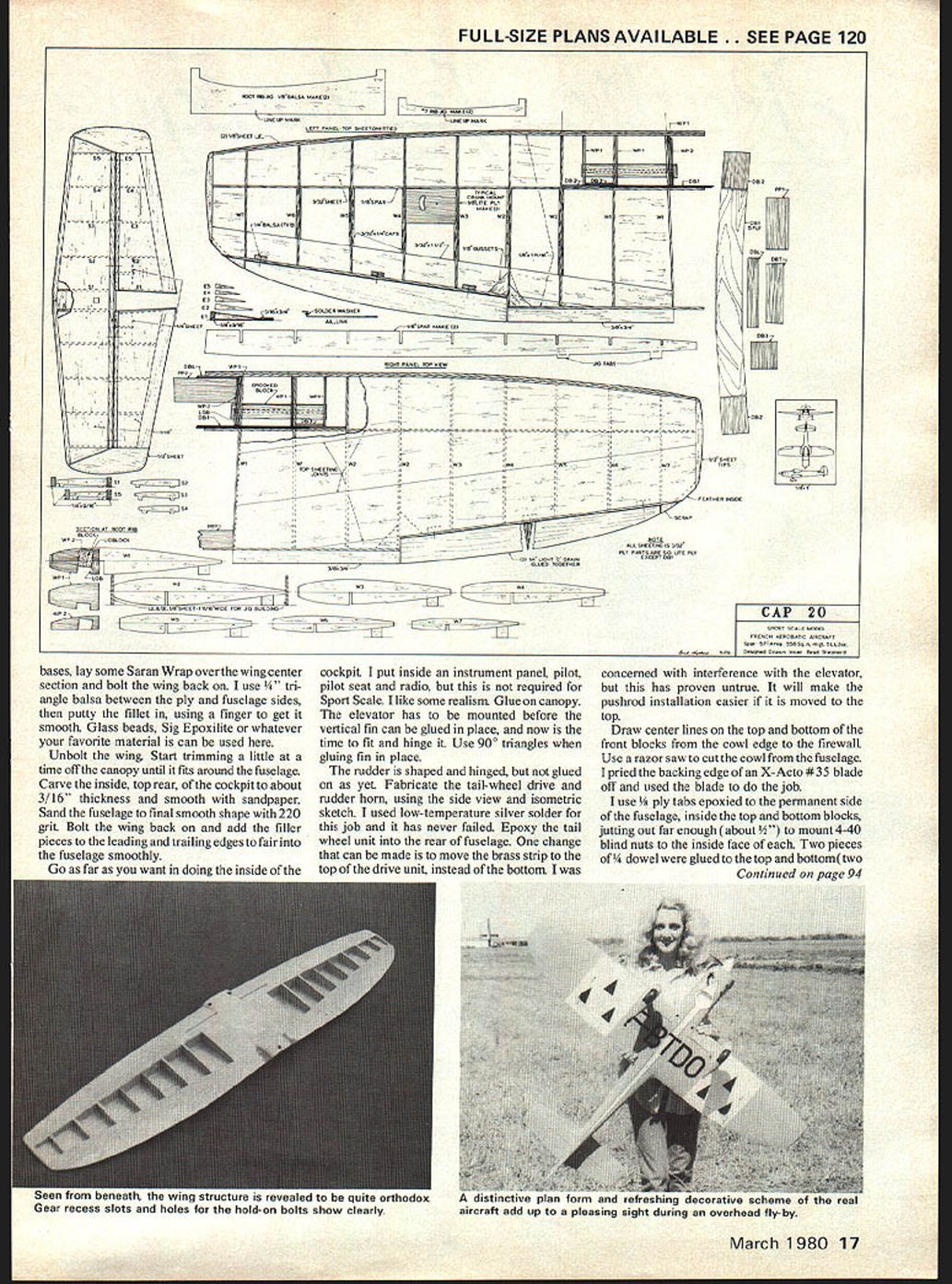
Wing construction — overview and steps
- Cut wing ribs from medium/light 3/32" sheet. Fit each rib to its slot in the spar and trim as necessary for a flush fit.
- Pin the spar over the plans using a 90° triangle to ensure straight set-up. Pin LE and TE 3/32" sheets in place.
- Check-fit ribs, trim for snug fit, and glue each rib in place.
- Fit the 3/32" LE sheeting, laying its edge over the center of the spar and the end over the center of rib #1. Trim corner of the 3" wide TE sheet to fit the 1/4" TE jig and rib #1. Glue in place, pinning firmly so ribs conform to the elliptical panel shape.
- Fit and glue the remaining top panel sheets; let dry overnight. Unpin, turn over, and pin down firmly on the bench.
- Sheet only the leading edge between the inside W2 rib and the tip at this time to allow for later installation of the landing gear structure.
- Glue the 3/32" x 1½" trailing edge sheeting in place after fitting to the TE jig. Fill the area between the two W2 ribs with 3/32" sheet.
- Fit the aileron crank to the 1/8" lite-ply mount (slot cut out) and glue in place on W3 and W4 ribs. Glue cap strips.
- Sheet from rib #7 to the tip with 3/32", and sheet the center section from the 1/4" TE to the spar. Glue 1/8" gussets as shown on the plans. Let the panel dry well before lifting from the board.
- Unpin and trim the 1/8" LE and TE pieces flush with the 3/32" sheeting top and bottom.
Note: Use epoxy on all plywood-to-hardwood joints.
Assembling panels and installing dihedral/center section
- Use a long, flat surface (an inexpensive interior panel door works well). Lay out a center line and the necessary guide lines to locate root and tip jigs.
- Pin root rib jigs and #7 jigs over the center line marks. Lay the two panels bottom-side up and trim spar ends for a good fit.
- When panels fit the jigs well and spars align, pin panels firmly to the jigs. Check-fit the dihedral brace DB1 and epoxy it in place. Glue DB2s, WP1, WP2 sub-ribs, DB3s, and grooved blocks per plans.
- Glue LGB and the vertical grooved block, glue DBL and DBT to the leading and trailing edges, then glue PP2 to WP2s and DBL. Sheet the center section between root ribs and let dry thoroughly.
Attach PP1 (epoxy) to bottom of trailing edge and set the wing aside to dry.
Ailerons and finishing the wing
- Before removing wing from jigs, sheet the bottom section between the root rib and W2 at the leading edge. Let dry.
- Remove jigs, sand tip sheeting square, and glue 1/2" tip blocks in place.
- Cut ailerons from light 1/4" sheet and tack-glue them in place on the 1/8" TE sheet. Glue the 3/16" x 3/4" trailing edge in place.
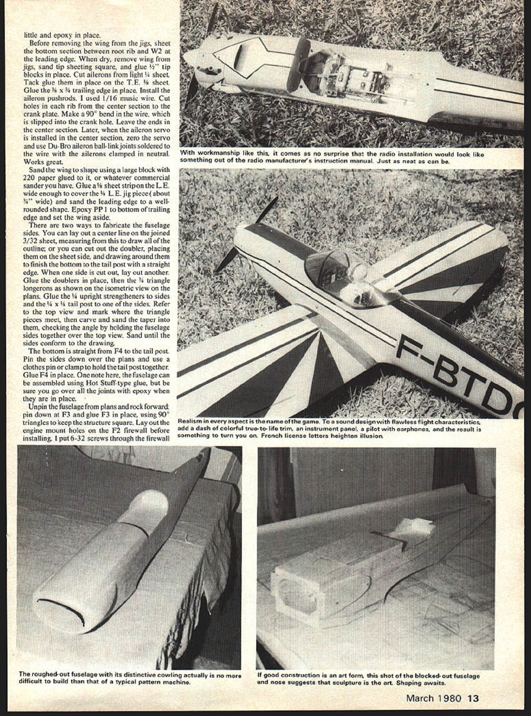
- Install aileron pushrods (I used 1/16" music wire). Cut holes in each rib from the center section to the crank plate. Make a 90° bend in the wire, slip into the crank hole and leave the ends in the center section.
- When the aileron servo is installed in the center section, zero the servo and use Du-Bro aileron ball-link joints soldered to the wire with the ailerons clamped neutral — this works well.
- Sand the wing to shape using a large block with 220-grit paper. Glue a 3/8" sheet strip on the LE wide enough to cover the 3/8" LE jig piece and sand the leading edge to a well-rounded shape.
Stabilizer, elevator and fin
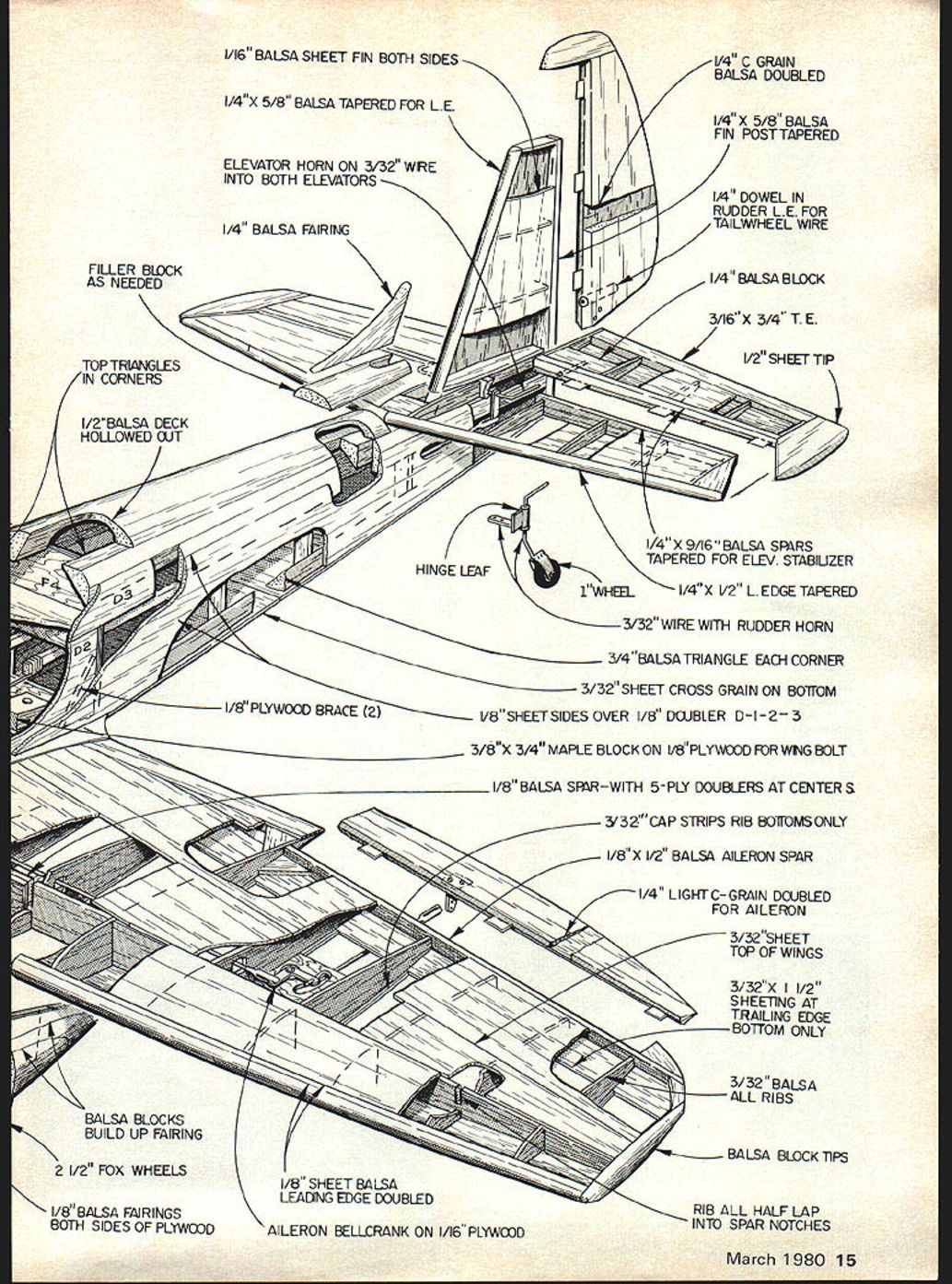
- Build stabilizer and vertical fin in the same manner as the wing panels, using 1/16" sheet instead of 3/32".
- Building the elevator: pin the 9/16" x 9/16" LE over the plans, pin the 3/16" TE in place, then glue 1/16" sheet between. Glue ribs onto the sheet and glue the top 1/16" sheet in place. When dry, remove and sand the TE to shape.
- Install the elevator joiner and horn assembly: pin elevator halves in place on the bench, line them up and mark where the horn wires will enter the elevators. Drill and relieve the LE a little and epoxy horn wires in place.
Fuselage construction
- Two ways to layout the fuselage sides:
- Draw a center line on joined 3/32" sheet and measure from it to draw the outline; or
- Cut out the doublers, place them on the sheet side, and draw around them to finish the bottom to the tail post with a straight edge.
- When one side is cut out, lay out and cut the other. Glue doublers in place, then glue 1/4" triangle longerons as shown on the isometric view of the plans.
- Glue 3/16" upright strengtheners to sides and the 1/4" x 1/2" tail post to one side.
- Refer to the top view and mark where triangle pieces meet; carve and sand the taper into them, checking the angle by holding the fuselage sides together over the top view. Sand until sides conform to the drawing.
- The bottom is straight from F4 to the tail post. Pin sides over the plans, use a clothes pin or clamp to hold the tail post together, and glue F4 in place. (Hot-cure adhesives like CA can be used to assemble the fuselage, but be sure to go over all joints with epoxy when in place.)
- Unpin, rock forward, pin down at F3 and glue F3 in place using 90° triangles to keep structure square.
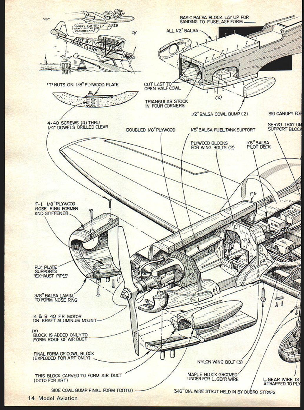
- Lay out engine mount holes on the F2 firewall before installing. I put 6-32 screws from the back side; solder a short piece of wire into the screw slots, then epoxy them to the firewall with the mount in position on the front side. Glue the firewall in place.
Tank, cockpit, and cowl
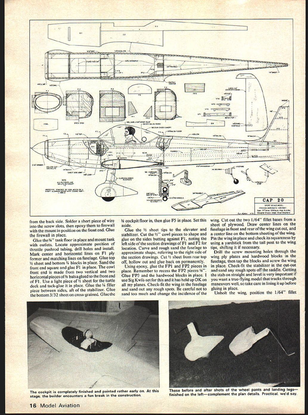
- Glue the 1/8" tank floor in place and mount tank with outlets. Locate approximate position for throttle pushrod tubing, drill holes and install.
- Mark center and horizontal lines on the F1 ply former and matching lines on the fuselage. Glue top 1/8" sheet and bottom 3/32" blocks in place. Sand front end square and glue F1 in place.
- The cowl front end is made from two vertical and two horizontal pieces of 3/16" balsa glued to the front of F1. Use a light 1/8" sheet for the turtledeck and tack-glue it in place. Glue the 1/4" filler piece between sides aft of the stabilizer.
- Glue the bottom 3/32" sheet on cross-grained, glue the 1/8" cockpit floor in, then glue F5 in place. Set this assembly aside.
- Glue the 1/8" sheet tops to the elevator and stabilizer. Cut and glue 1/8" cowl pieces to shape, butting against F1 and noting left/right from plans. Carve and rough-sand the fuselage to approximate shape following the section drawings. Cut rear top 1/8" sheet off, hollow it out and glue back on permanently.
- Using epoxy, glue FP1 and FP2 pieces in place, recessing FP2 pieces 1/8". Glue FP3 and hardwood blocks in place (Sig Kwik-set is recommended for these joints).
Wing fitting and alignment
- Check-fit the wing in the fuselage and sand any rough spots. Be careful not to sand too much and change the wing incidence.
- Cut out two 1/64" fillet bases from plywood. Draw center lines on fuselage in front and rear of the wing cutout and a center line on the bottom sheeting of the wing. Pin the wing in place and check squareness with a yardstick from tail post to wingtips; shift as necessary.
- Drill through screw mounting holes through the wing ply plates and hardwood blocks in the fuselage, tap the blocks, and screw the wing in place.
- Check-fit the stabilizer in its saddle and sand any rough spots. Getting the stab straight and level is very important for a true-flying model.
Canopy, tail assembly, and tailwheel
- Unbolt the wing. Trim the canopy a little at a time until it fits around the fuselage. Carve the inside top rear of the cockpit to about 3/16" thickness and smooth with sandpaper.
- Sand the fuselage to final smooth shape with 220-grit paper. Bolt the wing back on and add filler pieces to the LE and TE fillets to fair into the fuselage smoothly.
- Fit and hinge the elevator before gluing the vertical fin in place. Use 90° triangles when gluing the fin.
- Shape and hinge the rudder, but do not glue it on yet. Fabricate the tail-wheel drive and rudder horn using the side view and isometric sketch. Low-temperature silver solder works well for the tailwheel unit; epoxy it into the rear fuselage.
- One change you can make: move the brass strip to the top of the tail-wheel drive unit (instead of the bottom) to ease pushrod installation — interference with the elevator proved not to be an issue in my build.
Cowl attachment and serviceability
- Draw center lines on top and bottom of the front blocks from the cowl edge to the firewall. Use a razor saw to cut the cowl from the fuselage.
- I use 1/8" ply tabs epoxied to the permanent side of the fuselage inside the top and bottom blocks, jutting out about 1/8" to mount 4-40 blind nuts to the inside face. Glue two pieces of 1/4" dowel to the top and bottom over the tab locations (one top and one bottom, about 1" from front and back). Tape the cowl on tightly and drill 3/32" holes through the middle of the dowels and through the tabs. Enlarge tab holes to receive blind nuts, screw the cowl on and secure the blind nuts. Remove the cowl and dab a little epoxy on the blind nuts. Countersink the holes in the 1/4" dowels and use flat-head screws for a neat job.
Filling, sanding, covering and finishing
- My wing is MonoKoted; the rest of the plane received a coat of uncut butyrate clear. When dry, sand smooth with 220-grit.
- Thin some dope and use light Silkspan to cover the entire framework. Apply two or three coats of 50/50 dope, sanding between coats.
- Apply a coat or two of balsa filler until the surface is smooth. Then apply the color — I used orange lightened with yellow and a few dabs of white to match the MonoKote.
- Keep the model light from the wing aft. My CAP balanced on the CG mark without adding weight. The model can be flown with anything from a good .40 up to a .60 engine; a .60 should work fine. A 10-oz tank should fit in the available space.
Final assembly tips
- After covering, lay some Saran Wrap over the wing center section and bolt the wing back on. Use 1/4" triangle balsa between ply and fuselage sides, then putty the fillet in and smooth with your finger. Glass beads, Sig Epoxilite, or your favorite filler can be used.
- Go as far as you want in detailing the cockpit. I installed an instrument panel, pilot, pilot seat and radio for realism, but this is not required for Sport Scale.
- Glue on the canopy. Mount elevator and finish installing fin and rudder. Install the tailwheel and check linkages.
Recommended control throws and gear
- Rudder: 2" each side (measured at the trailing edge of the rudder).
- Aileron: 3/4" up and down (measured at the outboard tip).
- Elevator: 1" up and down.
The CAP has a fairly long tail moment and is not overly "squirrelly." If you fly from anything but a smooth concrete or asphalt runway, I recommend using 3/16" music wire for the landing gear struts instead of the 5/32" shown on the plans.
Research could turn up differences among CAPs now flying; some have different color schemes and there is a modified, lighter, more powerful version of the CAP 20.
Materials and parts (extracted notes)
- 1/16" balsa sheet — fin both sides
- 1/4" x 5/8" balsa tapered for LE
- Elevator horn on 3/32" wire into both elevators
- 1/4" balsa fairing, filler block as needed, top triangles in corners
- 1/2" balsa deck hollowed out
- Hinge leaf
- 1" wheel (or 2½" Fox wheels as noted)
- 1/4" C-grain balsa doubled
- 1/4" x 5/8" balsa fin post tapered
- 1/4" dowel in rudder LE for tailwheel wire
- 1/4" balsa block
- 3/16" x 3/4" trailing edge
- 1/2" sheet tip
- 1/4" x 9/16" balsa spars tapered for elevator/stabilizer
- 1/4" x 1/2" leading edge tapered
- 3/32" wire with rudder horn
- 3/4" balsa triangle each corner
- 3/32" sheet cross grain on bottom
- 1/8" plywood brace (2)
- 1/8" sheet sides over 1/8" doubler D-1-2-3
- 3/8" x 3/4" maple block on 1/8" plywood for wing bolt
- 1/8" balsa spar — with 5-ply doublers at center
- 3/32" cap strips — rib bottoms only
- 1/8" x 1/2" balsa aileron spar
- 1/4" light C-grain doubled for aileron
- 3/32" sheet top of wings
- 3/32" x 1½" sheeting at trailing edge bottom only
- 3/32" balsa all ribs
- Balsa block tips (build-up fairing)
- Ribs all half-lap into spar notches
- 1/8" sheet balsa leading edge doubled
- Aileron bellcrank on 1/16" plywood
- 1/8" balsa fairings both sides of plywood
Acknowledgements
I want to thank Bob Wischer for his help and encouragement throughout this project. Jerry Nelson has always been in front with new innovations in modeling, and his efforts to promote models that look and fly like their full-size counterparts are bearing fruit with events such as the Las Vegas TOC and the IMAC organization. Glen and Hazel Sigg and their gang in Iowa are promoting the IMAC philosophy — if you build this CAP, sashay up there next year and enjoy the "bash" they put on for us modelers.
Transcribed from original scans by AI. Minor OCR errors may remain.

