
Cap 21
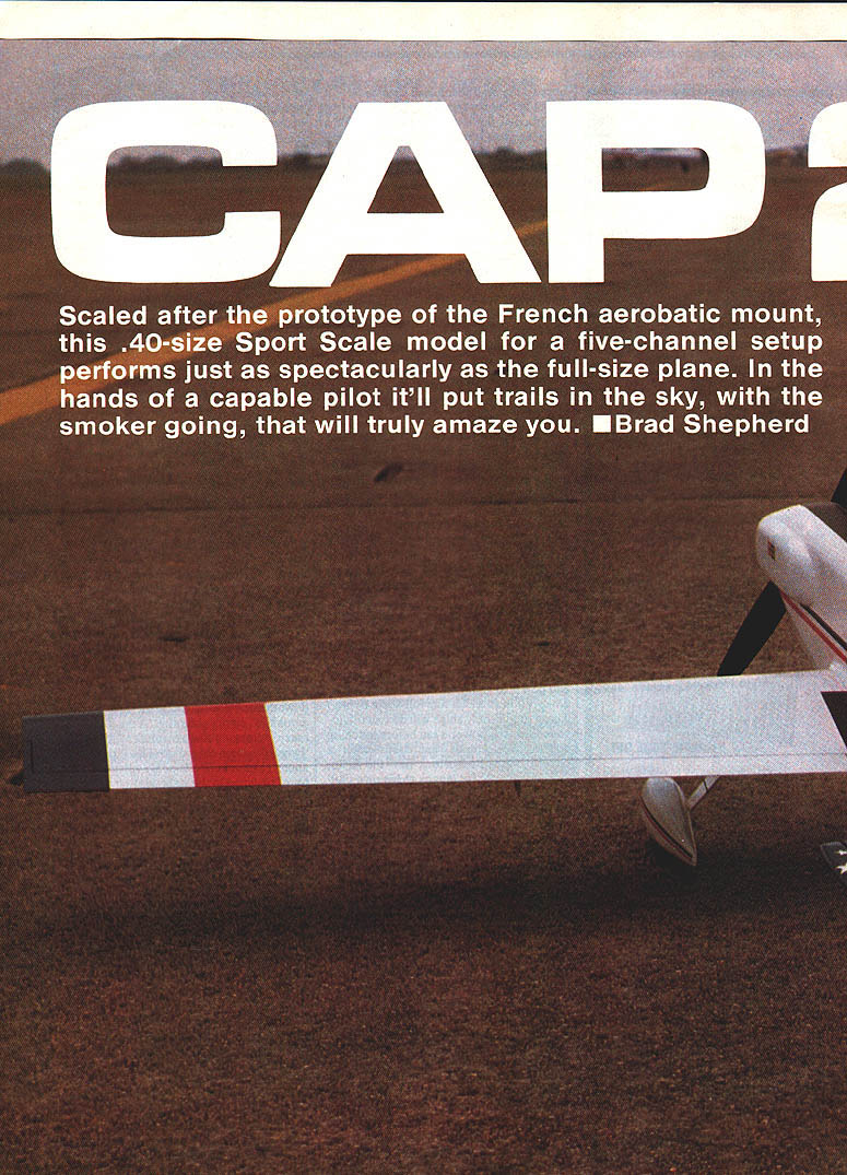
Scaled after the prototype of the French aerobatic mount, this .40-size sport-scale model for a five-channel setup performs just as spectacularly as the full-size plane. In the hands of a capable pilot it'll put trails in the sky, with the smoker going, that will truly amaze you. — Brad Shepherd
Background
It is probably safe to say that our French friends across the sea are nonconformists. Not to be outdone by the Pitts, Stephens, Lasers, Zlins, etc., that seem to be dominating full-size World Aerobatic Championships, they designed an aircraft that appears ready to put them in a position to attain the coveted WC gold. Giving up on the CAP 20 series because of its shortcomings in snap maneuvers, the designers used an entirely different approach for the CAP 21.
The wing uses a highly unorthodox airfoil and has the highest aspect ratio of world-class mounts. That is unusual when you consider some Aresti-pattern maneuvers that call for fast roll rates. What they achieved, though, is an aircraft that rolls almost as fast at low speeds as it does at high speeds — no doubt due to the combination of airfoil, aspect ratio, and long ailerons. Coming in at over 1,000 pounds, it is about 200 pounds heavier than the Pitts and Lasers, but apparently that does not hurt its vertical capability in competition maneuvers. It will not roll like a Kermit Weeks Special, but that is not required for "in the box" flying.
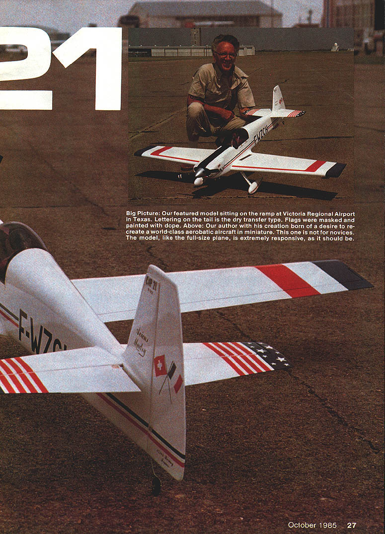
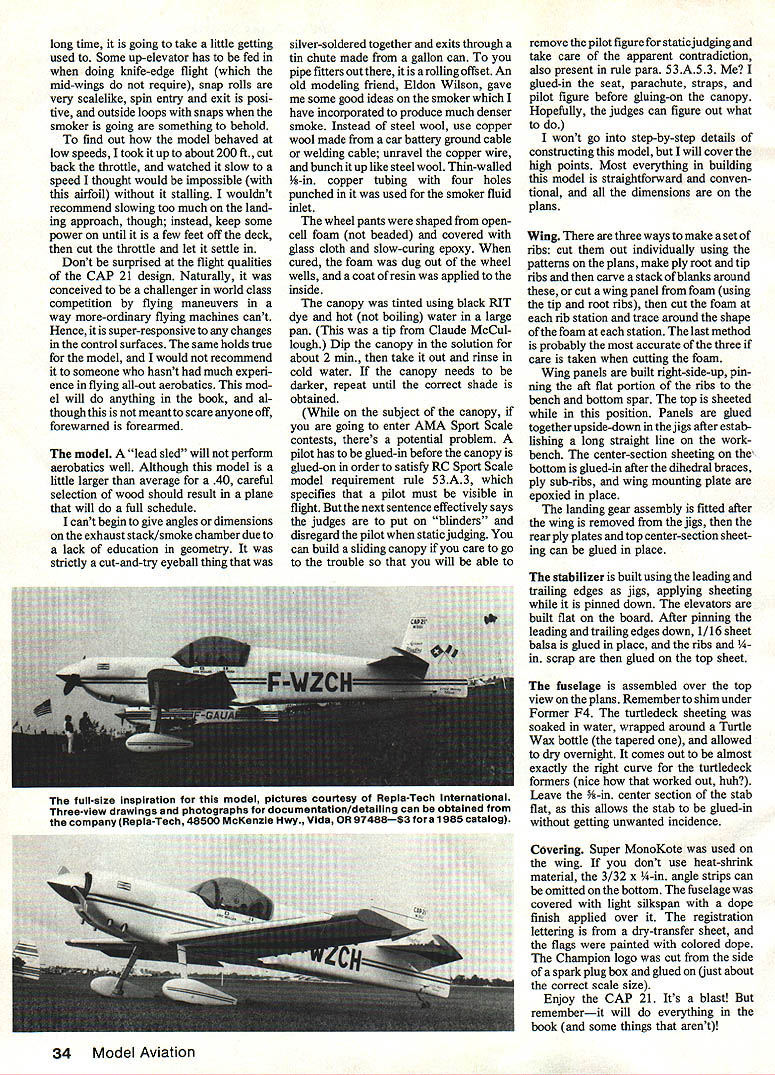
The prototype F-WZCH showed up at the 1980 World Championships and has since been joined by at least two others, F-GAUP and F-GAUK, which competed in the 1982 World Champs. The latter two have shorter ailerons, no wheel pants, slightly different canopies, and a turquoise-blue basic color. I had intended to build a model based on F-GAUP, but not having any turquoise heat-shrink covering, I built the F-WZCH prototype instead.
If we can find one word to describe this airplane, it is simplicity — and that same attribute guided the model design, using readily obtainable balsa and plywood sizes.
First flights and setup
The model did not fly perfectly on the first hop. Our club flies from a grass strip in a developing Community Center Complex that is a little bumpy, which encourages holding some extra up-elevator when accelerating with a taildragger.
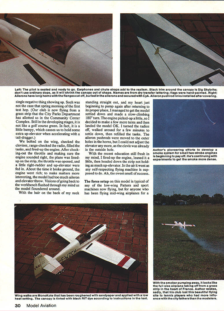
We bolted on the wing, checked the clevises, range-checked the radio, filled the tanks, and started the engine. After checking throttle response, the plane was lined up, the throttle opened, and a little right rudder and up elevator were applied. About the time it broke ground, the engine went rich; to make matters worse, the model had too much aileron and elevator throw. Visions of going back to the workbench flashed through my mind as the model floundered.
With hair on the back of my neck standing straight out, and my heart settling back to normal, I managed to get the model under control and made a slow-climbing 180° turn. The engine picked up a little, so I made a few more turns and landed the model okay. After shutting down and calming down, I refilled the tanks and moved the aileron pushrods to the outer holes in the horns. The elevator clevis was already at its outer hole, so no further elevator reduction was possible then.
On the next flight I leaned the engine a little, reduced the up-elevator used during takeoff, and the model flew very nicely. Ah — the sweet smell of success.
Flight characteristics
The servo setup on this model is typical of low-wing pattern and sport machines, but for anyone who has been flying mid-wing airplanes for a long time, it is going to take a little getting used to. Some up-elevator is required during knife-edge flight (mid-wings do not require as much), snap rolls are very scale-like, spin entry and exit are positive, and outside loops with snaps while the smoker is running are spectacular.
To test low-speed behavior I took it to about 200 ft, cut the throttle, and watched it slow to a speed I thought the airfoil would not permit without stalling. I wouldn't recommend slowing too much on the landing approach; instead, keep some power on until a few feet off the deck, then cut the throttle and let it settle in.
Don't be surprised at the CAP 21 design's responsiveness. It was conceived as a challenger in world-class competition; hence, it is super-responsive to any changes in the control surfaces. The same holds true for the model, and I would not recommend it to someone who hasn't had experience flying all-out aerobatics. This model will do anything in the book — and some things that aren't.
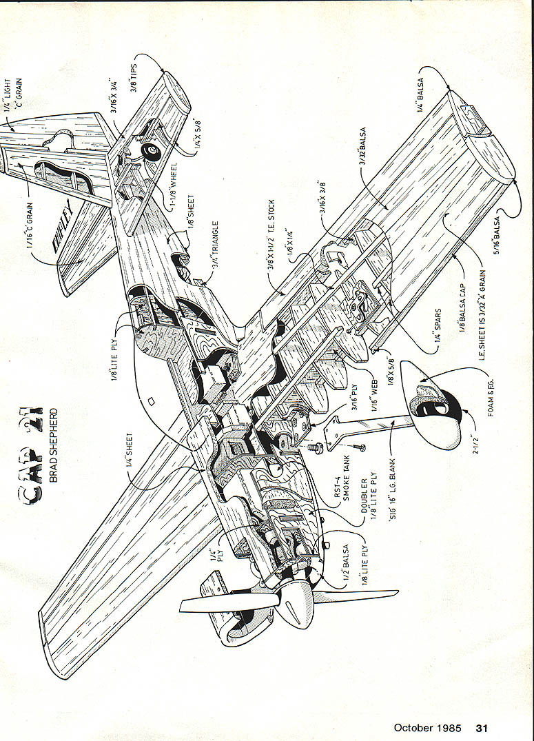
The model
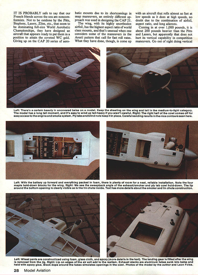
A "lead sled" will not perform aerobatics well. Although this model is a little larger than average for a .40, careful selection of wood should result in a plane that will do everything it should.
Exhaust/smoke system
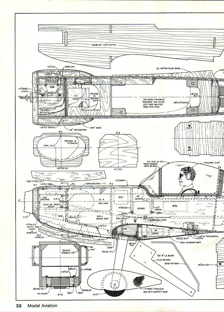
- I can't give exact angles or dimensions on the exhaust stack/smoke chamber — it was a cut-and-try eyeball job that was silver-soldered together and exits through a tin chute made from a gallon can. To pipe-fitters, it's a rolling offset.
- An old friend, Eldon Wilson, suggested improvements to the smoker. Instead of steel wool, use copper wool made from a car-battery ground cable or welding cable: unravel the copper wire and bunch it up like steel wool.
- Thin-walled 1/8-inch copper tubing with four holes punched in it was used for the smoker-fluid inlet.
Wheel pants
- Shaped from open-cell foam (not beaded), then covered with glass cloth and slow-curing epoxy.
- After curing the foam was dug out of the wheel wells and a coat of resin applied to the inside.
Canopy
- Tinted using black RIT dye and hot (not boiling) water in a pan. Dip the canopy for about 2 minutes, then rinse in cold water. Repeat to darken further if needed.
- Note on AMA Sport Scale: rule 53.A.3 requires a pilot to be visible in flight, but static judging may disregard the pilot. You can build a sliding canopy to remove the pilot figure for static judging. I glued in the seat, parachute, straps, and pilot figure before gluing the canopy; judges should understand the intent.
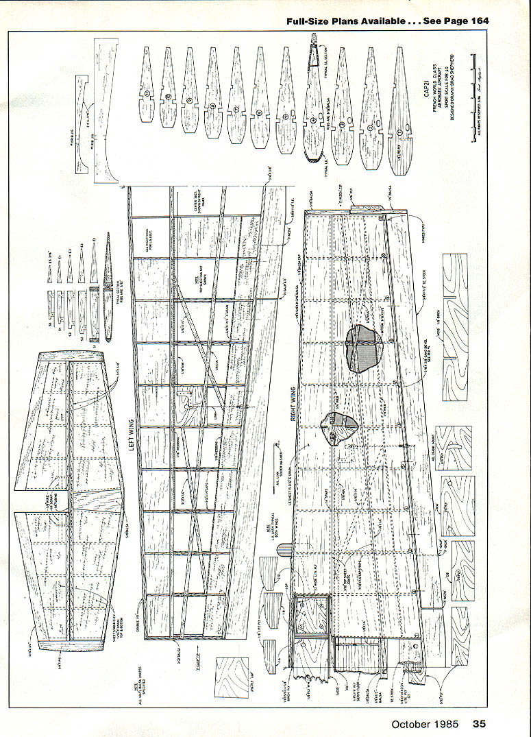
I won't give step-by-step construction details here, but I will cover the high points. Most building is straightforward and conventional, and all dimensions are on the plans.
Materials and plan notes
- All material balsa unless specified.
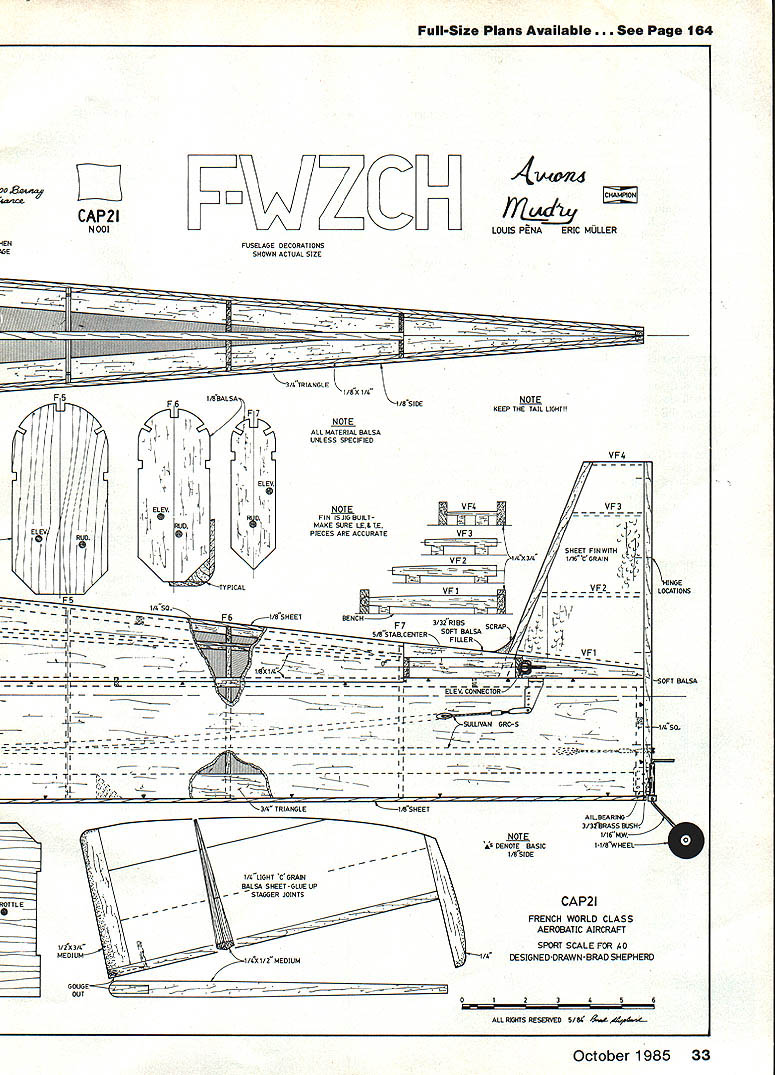
- Ribs should be built — make sure left and right pieces are accurate.
- Keep the tail light!
- Fuselage decorations shown actual size.
- Fuselage ID: F-WZCH.
- Manufacturer: Avions Mudry.
- Names listed: Louis Peña, Eric Müller.
- Plan ID: CAP21 N001.
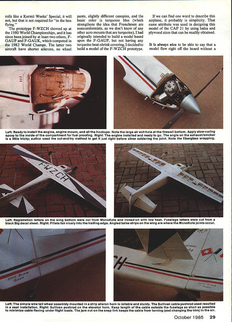
- Elevator connector: Sullivan GRC-5.
- Typical stock sizes shown on plans: 1/8" sheet, 3/32" ribs, 5/8" stab center, etc.
Building highlights
Wing
There are three ways to make a set of ribs:
- Cut them out individually using the patterns on the plans.
- Make plywood root and tip ribs, then carve a stack of blanks around these.
- Cut a wing panel from foam (using the tip and root ribs), then cut the foam at each rib station and trace around the foam shape at each station — this last method is probably the most accurate if care is taken when cutting the foam.
Wing panels are built right-side-up, pinning the aft flat portion of the ribs to the bench and bottom spar. The top is sheeted while in this position. Panels are glued together upside-down in the jigs after establishing a long straight line on the workbench. Center-section bottom sheeting is glued in after the dihedral braces, ply sub-ribs, and wing-mounting plate are epoxied in place.
The landing-gear assembly is fitted after the wing is removed from the jigs, then the rear ply plates and top center-section sheeting can be glued in place.
Stabilizer and elevators
The stabilizer is built using the leading and trailing edges as jigs, applying sheeting while pinned down. Elevators are built flat on the board. After pinning the leading and trailing edges, 1/16-inch sheet balsa is glued in place, then the ribs and 1/4-inch scrap filler are glued on the top sheet. Leave the 9/16-inch center section of the stab flat to allow the stab to be glued in without introducing unwanted incidence.
Fuselage
Assemble the fuselage over the top view on the plans. Remember to shim under former F4. Turtledeck sheeting was soaked in water, wrapped around a tapered bottle (a Turtle Wax bottle was used), and allowed to dry overnight to form the correct curve.
Covering
- Super MonoKote was used on the wing. If you don't use heat-shrink covering, the 3/32 x 3/4-inch angle strips on the bottom can be omitted.
- The fuselage was covered with light silkspan and finished with dope.
- Registration letters were from a dry-transfer sheet; flags were painted with color dope.
- The Champion logo was cut from the side of a spark-plug box and glued on — about the correct scale size.
Enjoy the CAP 21. It's a blast! But remember — it will do everything in the book (and some things that aren't).
Transcribed from original scans by AI. Minor OCR errors may remain.

