
Capacitive Discharge Ignition System
Emil Svercl
Photo captions
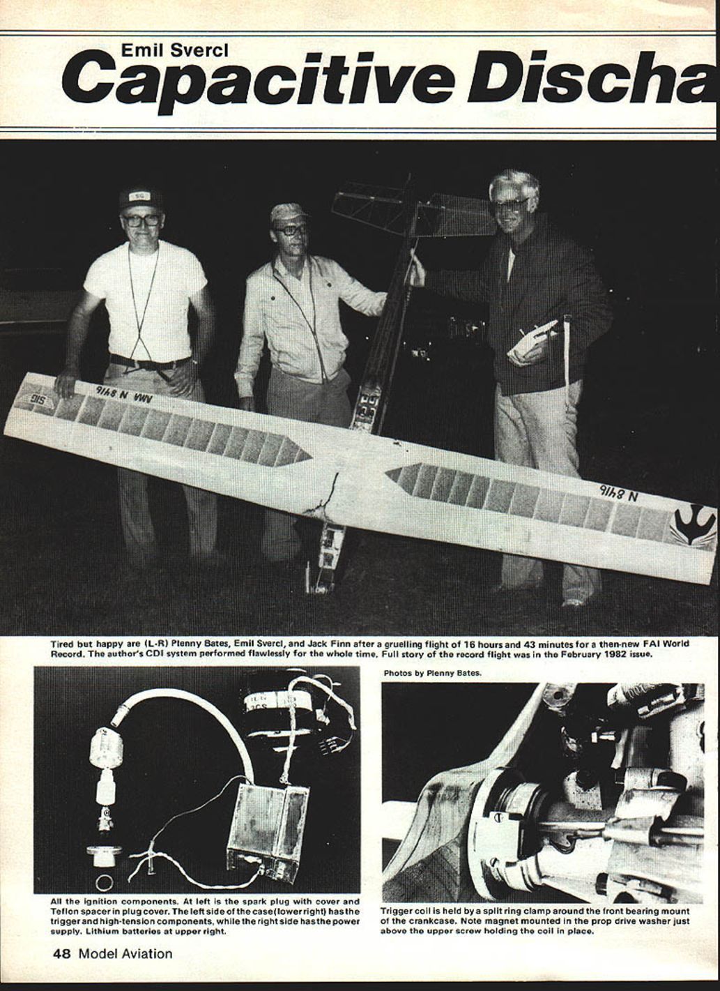
- Tired but happy are (L–R) Plenny Bates, Emil Svercl, and Jack Finn after a gruelling flight of 16 hours and 43 minutes for a then-new FAI World Record. The author's CDI system performed flawlessly for the whole time. Full story of the record flight was in the February 1982 issue. Photos by Plenny Bates.
- All the ignition components. At left is the spark plug with cover and Teflon spacer in plug cover. The left side of the case (lower right) has the trigger and high-tension components, while the right side has the power supply. Lithium batteries at upper right.
- Trigger coil is held by a split-ring clamp around the front bearing mount of the crankcase. Note magnet mounted in the prop drive washer just above the upper screw holding the coil in place.
Overview
There is a need for a lightweight, efficient, trouble-free spark ignition system for model aircraft. Interest from Old-Timer, Texaco, RC Duration record attempts, sport flying, and inexpensive fuel should stimulate further development of breakless capacitor-discharge (CDI) systems. CDI systems give higher efficiency and greater reliability than traditional spark ignition systems. The short-duration spark has little tail and results in less spark plug electrode erosion.
If you can wind a coil and have some electronic design background, building this system should be within your capabilities. The system described was developed by the author and the Cedar Rapids Skyhawks team and proved reliable during long-duration record attempts.
Power and efficiency
- Fully shielded system power: about 125 mA at 6 V (≈750 mW).
- Unshielded system power: about 500 mW.
- A shielded system should give 30-plus running hours on six ounces of lithium battery.
- In past 50-hour runs, plug inspection has been the only required attention, with little electrode erosion.
Coil construction
Core and primary
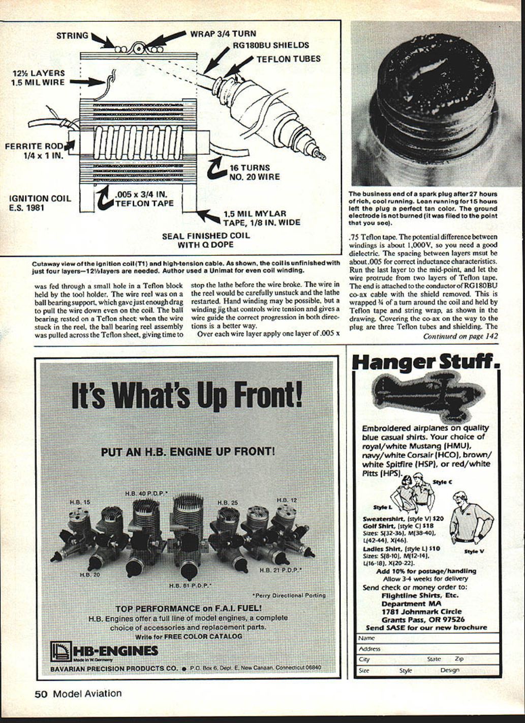
- Core: ferrite rod, 1/4 in. diameter by 1 in. long.
- Primary: lay 16 turns of two parallel #20 wires; then remove one wire to obtain the needed spacing for the primary winding. Hold wire in place with Q-dope.
- Build up end rings equal in thickness to the #20 wire (use 1/8-in. wide Mylar tape where noted).
- Cover the primary with two layers of 0.005 in. x 3/4 in. Teflon tape.
Secondary winding
- The secondary is the most difficult part to wind. Recommended: 125 even layers using 1.5 mil wire.
- Use a winding jig that controls wire tension and gives a wire guide for correct progression in both winding directions. The author used a home-built, computer-controlled lead screw on a Unimat permitting progression of the tool holder at 1.5 mil per coil revolution. Hand winding may be possible but is more difficult.
- Over each wire layer apply one layer of 0.005 in. x 3/4 in. Teflon tape. The potential difference between windings may be several thousand volts, so good dielectric spacing is required.
- Spacing between layers should be about 0.005 in. for correct inductance characteristics.
- Run the last layer to the midpoint and let the wire protrude through two layers of Teflon tape. Attach this end to the conductor of RG-180B/U coax with the shield removed. Wrap the coax 3/4 of a turn around the coil and hold with Teflon tape and string wrap. Cover the coax on the way to the plug with three Teflon tubes and shielding.
Winding tips
- Feed the fine wire through a small hole in a Teflon block held by the tool holder.
- Place the wire reel on a ball-bearing support to give just enough drag to pull the wire down evenly. Rest the ball bearing on a Teflon sheet so that if the wire sticks in the reel the assembly will slide and give time to stop the lathe before the wire breaks. Unstick the reel and restart carefully.
- Seal the finished coil with Q-dope to protect windings from abrasion and to hold end rings.
High-tension lead and plug cover
- Use RG-180B/U coax for the high-tension lead; ordinary automotive or aircraft cable has too much capacitance and will reduce the spark significantly.
- Protect and insulate the high-tension cable with three nested Teflon tubes. The inner two tubes are used for strain relief and insulation; note the notches in their ends. The inner tube's notch fits in a hole in the glass-epoxy board that holds one end of the coil. The middle tube's notch fits in a hole in the outer case. The outer Teflon tube may be split and used as a spacer between the inner insulation and the braided copper shield.
- Use blue aircraft cable for the outer ground shield. Carefully unbraid and clean the ends before soldering to the copper tube, which is soldered to the case and held in the split clamp of the spark plug cover.
- The spark plug cover should include Teflon fillers inside to reduce the chance of a direct spark to ground. String-wrap the high-tension lead near the plug: three-quarters of a turn and one-half to two layers as required.
Trigger
- The trigger is a small single-play tape-head pickup removed from its metal case.
- A small ceramic magnet, ground to a round shape (observe polarity), is glued into a hole in an aluminum prop-driver tube. Mount the tape head near the magnet's face. The magnet must produce a positive pulse.
- Any magneto coil that will produce a pulse of a few millivolts will work. Breaker points were not used because they may be less reliable. An LED-photodiode triggering system was tried but found too bulky and delicate.
Electronics and construction
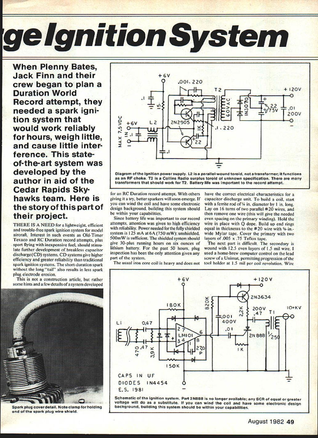
- Some electronic parts used originally are now obsolete. Substitute parts should have equal or higher ratings; values shown in older schematics are often close to minimums.
- Any good DC-to-DC power supply of the correct voltages and 10 mA or more of output will work.
- Diodes and other semiconductors should have appropriate voltage and speed characteristics for CDI use.
- An SCR may substitute for obsolete switching transistors like the 2N888; select equal or higher voltage ratings.
- T2 in the original design is a Collins Radio surplus toroid; similar toroidal transformers of the correct type should work.
- L2 is used as a parallel-wound toroid transformer functioning as an RF choke. Proper shielding and grounding will minimize radiated interference.
Chassis and RF shielding
- Use thin single-sided PCB (1/32 in.) with copper on the outside serving as an RF shield, or 1/16-in. double-sided board with the outside copper as RF shield and the inside etched to form the circuit. Mount parts on pads; avoid unnecessary holes for part mounting.
- Solder the RF shield to the case where appropriate. Keep wiring short and neat to minimize stray inductance and pickup.
Spark plug cover detail
- Use a Teflon spacer inside the plug cover and shield the high-tension lead.
- Fit the braided shield and copper tube to the case and clamp assembly. Use Teflon fillers inside the plug cover to reduce the chance of a spark to ground.
Schematic and component notes
- Use equal or higher ratings for substituted components; values shown in older diagrams may be near minimum acceptable values.
- Ensure diodes and switching devices meet voltage and current demands of the CDI pulse.
- Properly shield and ground the system to reduce RFI; L2 and the toroidal components serve as RF choke/isolation where indicated.
Final notes
- With attention to wiring neatness, shielding, and dielectric spacing, the CDI system is efficient, reliable, and suitable for long-duration model aircraft flights.
- Building the system requires some electronic skill and care in winding the coil, but it is within reach for a skilled hobbyist.
Transcribed from original scans by AI. Minor OCR errors may remain.

