
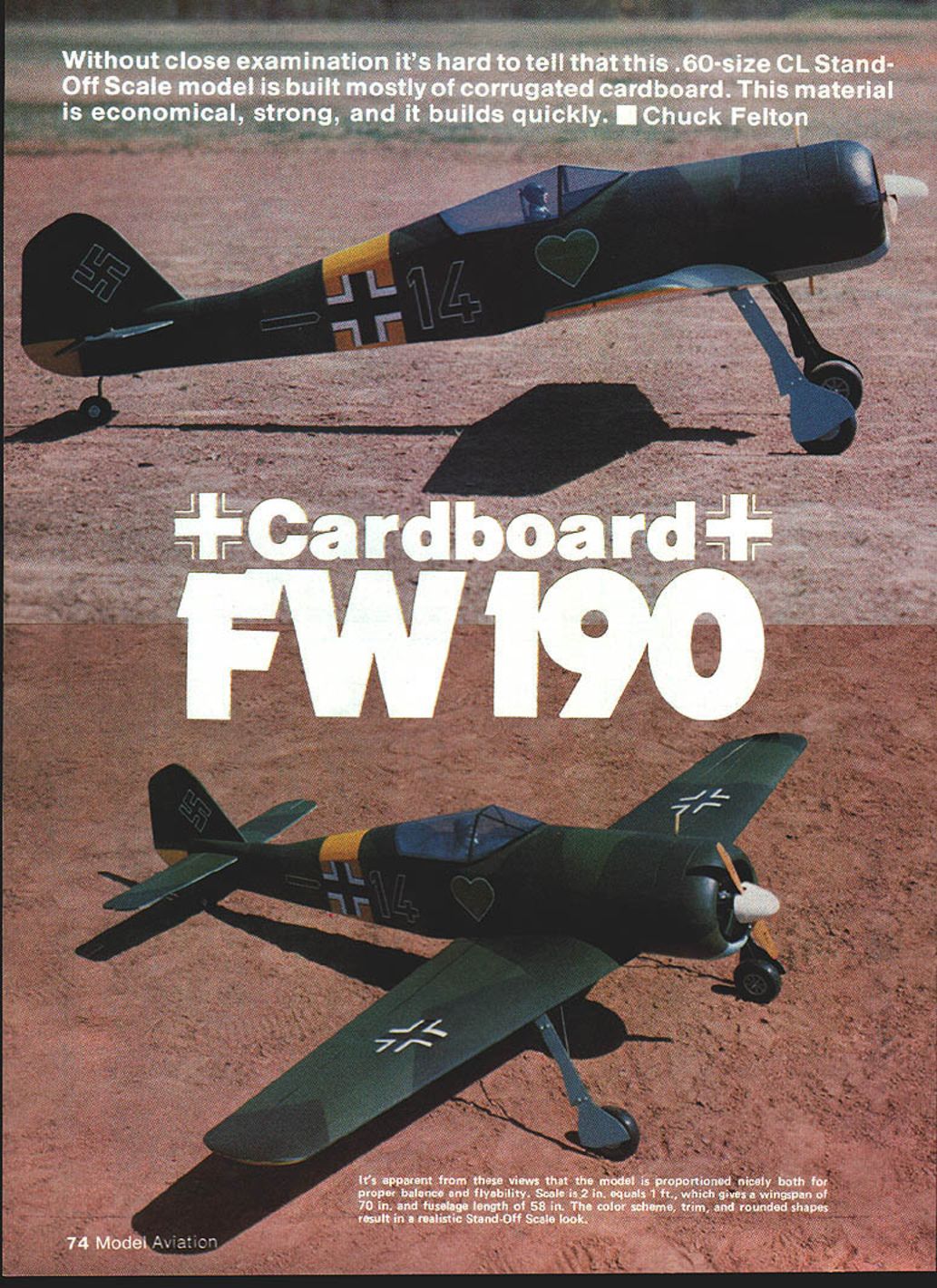
Cardboard: FW190
Without close examination it's hard to tell that this .60-size Control Line stand-off scale model is built mostly of corrugated cardboard. This material is economical, strong, and it builds quickly. — Chuck Felton
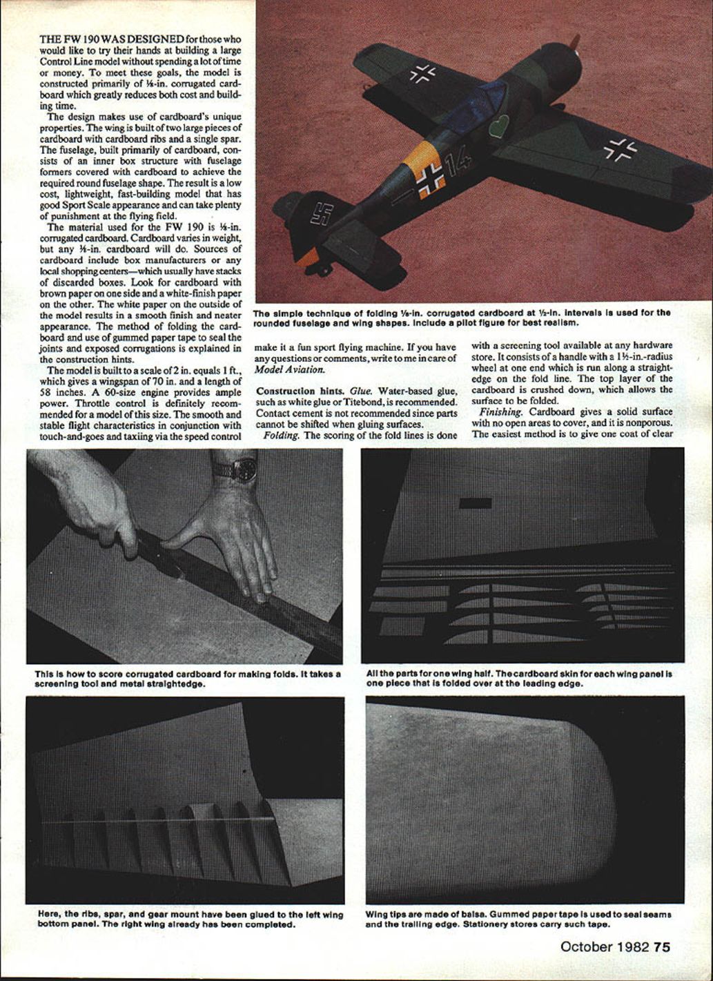
The FW 190 was designed for those who would like to try their hands at building a large Control Line model without spending a lot of time or money. To meet these goals, the model is constructed primarily of 1/4-in. corrugated cardboard which greatly reduces both cost and building time.
The design makes use of cardboard's unique properties. The wing is built from two large pieces of cardboard with cardboard ribs and a single spar. The fuselage, built primarily of cardboard, consists of an inner box structure with fuselage formers covered with cardboard to achieve the required round fuselage shape. The result is a low-cost, lightweight, fast-building model that has good sport-scale appearance and can take plenty of punishment at the flying field.
The material used for the FW 190 is 1/4-in. corrugated cardboard. Cardboard varies in weight, but any 1/4-in. cardboard will do. Sources of cardboard include box manufacturers or any local shopping centers — which usually have stacks of discarded boxes. Look for cardboard with brown paper on one side and a white-finish paper on the other. The white paper on the outside of the model results in a smooth finish and neater appearance. The method of folding the cardboard and use of gummed paper tape to seal the joints and exposed corrugations is explained in the construction hints.
The model is built to a scale of 2 in. = 1 ft., which gives a wingspan of 70 in. and a length of 58 in. A .60-size engine provides ample power. Throttle control is definitely recommended for a model of this size. The smooth and stable flight characteristics in conjunction with touch-and-goes and taxiing via the speed control make it a fun sport flying machine. If you have any questions or comments, write to me in care of Model Aviation.
Construction hints
Glue
- Use water-based glue, such as white glue or Titebond.
- Contact cement is not recommended since parts cannot be shifted when gluing surfaces.
Folding
- Score fold lines with a screening tool available at any hardware store. This tool has a handle with a 1-1/2-in.-radius wheel that is run along a straightedge on the fold line.
- The top layer of the cardboard is crushed down, allowing the surface to be folded.
Finishing
- Cardboard gives a solid, nonporous surface with no open areas to cover.
- The easiest method is one coat of clear dope followed by several coats of color dope.
- Covering films such as Solarfilm or MonoKote can be used, but a doped surface will result in a better bond.
Paper tape
- Cover all seams, joints and exposed edges with strips of gummed paper tape.
- Obtain a 1-in.-width roll from any stationery store. Cut a thin strip to length, dip it in water, and smooth it over the seam.
Construction
- Cut out all cardboard and wood parts using the template outlines. Be sure to note the direction of the corrugations.
- Score and fold cardboard parts as indicated on the plans.
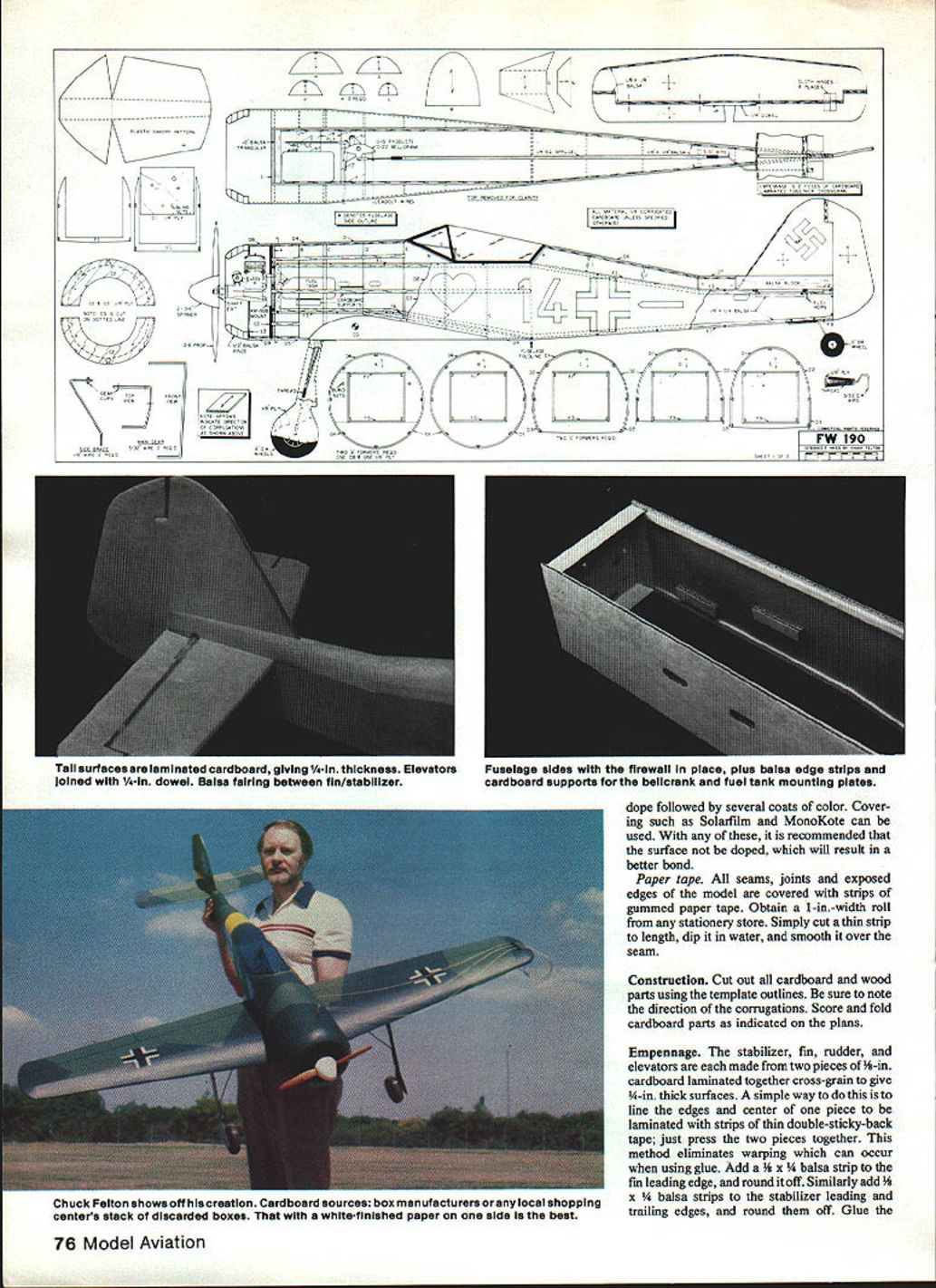
Empennage
- The stabilizer, fin, rudder, and elevators are each made from two pieces of 1/8-in. cardboard laminated together cross-grain to give 1/4-in. thick surfaces.
- A simple way to laminate: line the edges and center of one piece with strips of thin double-sticky-back tape and press the pieces together. This method eliminates warping which can occur when using glue.
- Add a 1/8 x 1/4-in. balsa strip to the fin leading edge and round it off.
- Add 1/8 x 1/4-in. balsa strips to the stabilizer leading and trailing edges and round them off.
- Glue the elevators to the stabilizer and join them with a 1/4-in. dowel.
- Seal raw edges with gummed paper tape.
- Hinge elevators to stabilizer with cloth hinges in four places.
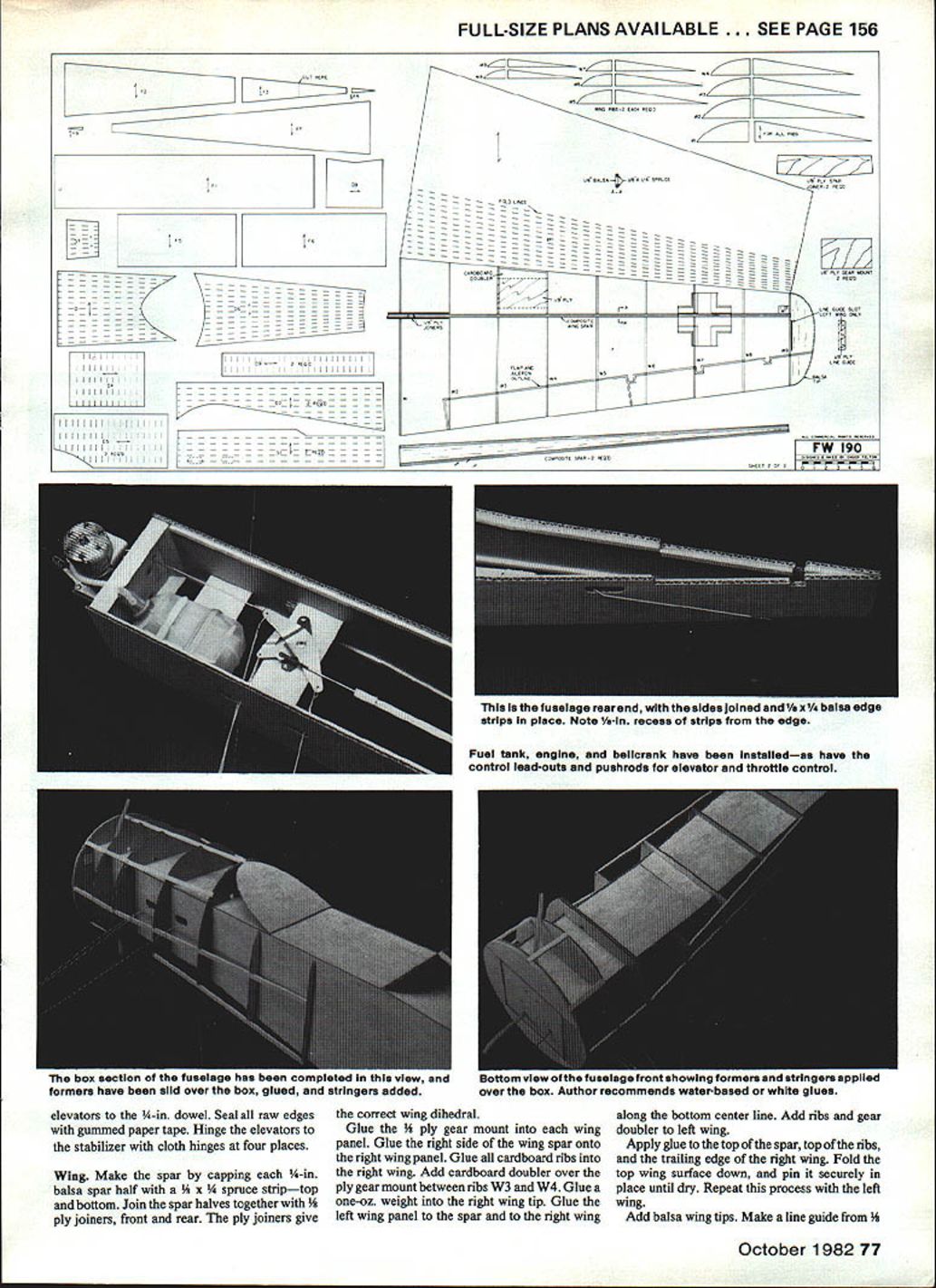
Wing
- Make spar capping from 1/8-in. balsa.
- Make spar halves from 1/4 x 3/4-in. strips for top and bottom. Join spar halves together with 4-ply joiners front and rear. Four-ply joiners give the correct wing dihedral.
- Glue a 1/8-in. ply gear mount to the wing panel.
- Glue the right-side wing spar onto the right wing panel and glue cardboard ribs to the right wing.
- Add a cardboard doubler over the ply gear mount between ribs W3 and W4.
- Glue the one-oz. weight into the right wing tip.
- Glue the left wing panel to the spar and to the right wing along the bottom center line. Add ribs and gear doubler to the left wing.
- Apply glue to the top of the spar, top of the ribs, and the trailing edge of the right wing. Fold the top wing surface down and pin it securely in place until dry. Repeat with the left wing.
- Add balsa wing tips.
- Make a line guide from 1/4-in. wire. Cut a slot in the left wing tip and glue the line guide in place.
- Cover the trailing edge and all seams of the wing with gummed paper tape.
Fuselage
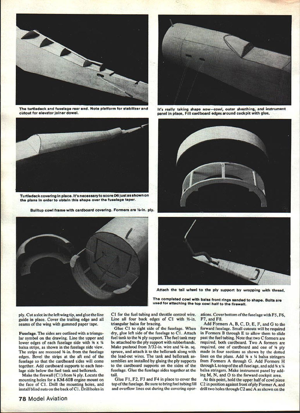
- The fuselage sides are outlined with a triangular symbol on the drawing.
- Line the upper and lower edges of each fuselage side with 1/8 x 1/4-in. balsa strips, recessed 1/16-in. from the fuselage edges. Bevel the strips at the aft end so the cardboard sides will come together.
- Add cardboard supports to each fuselage side below the fuel tank and bellcrank.
- Make the firewall (C1) from 3/8-in. ply. Locate mounting holes for a KM-60B engine mount on the face of C1. Drill the mounting holes and install blind nuts on the back of C1. Drill holes in C1 for the fuel tubing and throttle control wire.
- Line all four back edges of C1 with 1/2-in. triangular balsa for bracing.
- Glue C1 to the right fuselage side. When dry, glue the left side to C1.
- Attach the fuel tank to the 1/8-in. ply support. The fuel tank may be attached to the ply support with rubber bands.
- Make the pushrod from 3/32-in. wire and 1/8-in. sq. spruce, and attach it to the bellcrank along with the lead-out wires.
- Install the tank and bellcrank assemblies by gluing the ply supports to the cardboard supports on the sides of the fuselage.
- Glue the fuselage sides together at the tail.
- Glue F1, F2, F3 and F4 in place to cover the top of the fuselage. Be sure to bring fuel tubing fill and overflow lines out during the covering operations.
- Cover the bottom of the fuselage with F5, F6, F7, and F8.
- Add Formers A, B, C, D, E, F, and G to the forward fuselage. Small cutouts are required in Formers B through E to allow them to slide past the fuel tubing.
- Note: two C formers are required, both cardboard. Two A formers are required: one cardboard and one of 1/8-in. ply made in four sections as shown by the dotted lines on the plans.
- Add 1/4 x 1/4-in. balsa stringers from Formers A through G.
- Add Formers H through L to the top of the aft fuselage and add 1/8 x 1/4-in. balsa stringers.
- Make the instrument panel by adding M, N, and O to the forward cockpit area.
- Hold the upper half of cowl piece C2 in position against the front of ply Former A and drill two holes through C2 and A as shown on the plans. Install blind nuts to the rear side of Former A to be used for cowl attachment.
- The fuselage is now ready for covering. Glue D1 to the top of Formers C, D, E, and M.
- Add left and right side pieces of D2 to Formers C through G back to the fuselage fold line. Note that the left side of D2 has holes for lead-out wires. Bevel D2 at the fold line so that it faired into the fuselage lines.
- Add left and right side pieces D3 to Formers C through G back to the fuselage fold line and bevel at the fold line.
- Add D4 to the top of A, B and C.
- Add left and right side pieces D5 to the sides of Formers A, B and C.
- Add D8 to the bottom sides of the fuselage.
- Add D6 and D7 to the top aft fuselage.
- The fuselage sectional views on Sheet 1 of the plans show the location of covering pieces D1 through D5.
- Cover all fuselage seams with gummed paper tape.
Cowl
- The two cowl halves are built up by connecting pieces C2 and C3 with 1/8 x 1/4-in. balsa strips.
- Each half is then covered with D9.
- Add 1/8-in. balsa rings to C3 and sand to shape.
- Glue the lower portion of the cowl to Former A. The upper half is attached by bolts in C2 which fasten to the blind nuts in the back of Former A.
- Cut holes in the cowl for exhaust and needle valve.
- Coat the inside of the cowl and the front of Former A with epoxy.
- Drill mounting holes in the KM-60B mount. A shaft extension is used to give adequate propeller clearance.
Sub-assembly
- Cut a small notch in the aft fuselage under the elevator dowel to ensure smooth elevator movement.
- Glue the stabilizer to the fuselage and the fin to the top of the stabilizer.
- Add a balsa block to each side of the fin and sand to match the fuselage contour.
- Glue the rudder to the fin with the trailing edge offset approximately 3/16-in. to the outside of the flying circle.
- Make the tail wheel from 3/32-in. wire. Bend as shown, place on a 1/8-in. ply support, wrap with nylon thread, and smear with glue. When dry, glue in place in the bottom fuselage cutout.
- Make the main landing gear from 5/32-in. wire and the side braces from 1/8-in. wire.
- Attach the main gear and side braces to the 1/8-in. ply supports in the bottom wing with nylon gear clips.
- Attach braces to the main gear by wrapping with thread and smearing with glue.
- Attach the ply gear fairings to the main gear with nylon gear clips.
Finishing
- Paint and trim the model before gluing the wing to the fuselage.
- Give the entire model one coat of clear dope. Sand lightly with fine sandpaper where necessary.
- Color scheme: bottom of the model is aero blue; upper side is light and dark green with a yellow fuselage band and rudder base.
- All trim is MonoKote. Markings are black outlines with white fill, except the heart emblem which is bright green outlined with white. Aileron and flap outlines are black.
- Make the canopy from thin plastic, epoxy to the fuselage, and outline with strips of black MonoKote.
- Addition of guns, bombs, etc., is left to your imagination.
Final Assembly
- Glue the wing to the fuselage.
- Pass lead-out wires through the wing tip line guide and tie off.
- Attach a nylon control horn to the elevator and hook up the pushrod.
- Attach 4-in. wheels to the main gear and a 2-in. wheel to the tail gear.
- Attach a 12 x 6 prop and 2-1/4-in. spinner to the engine.
- Balance the model at the point shown on the plans. Your ship is now complete.
Transcribed from original scans by AI. Minor OCR errors may remain.

