
Cardboard P-51B
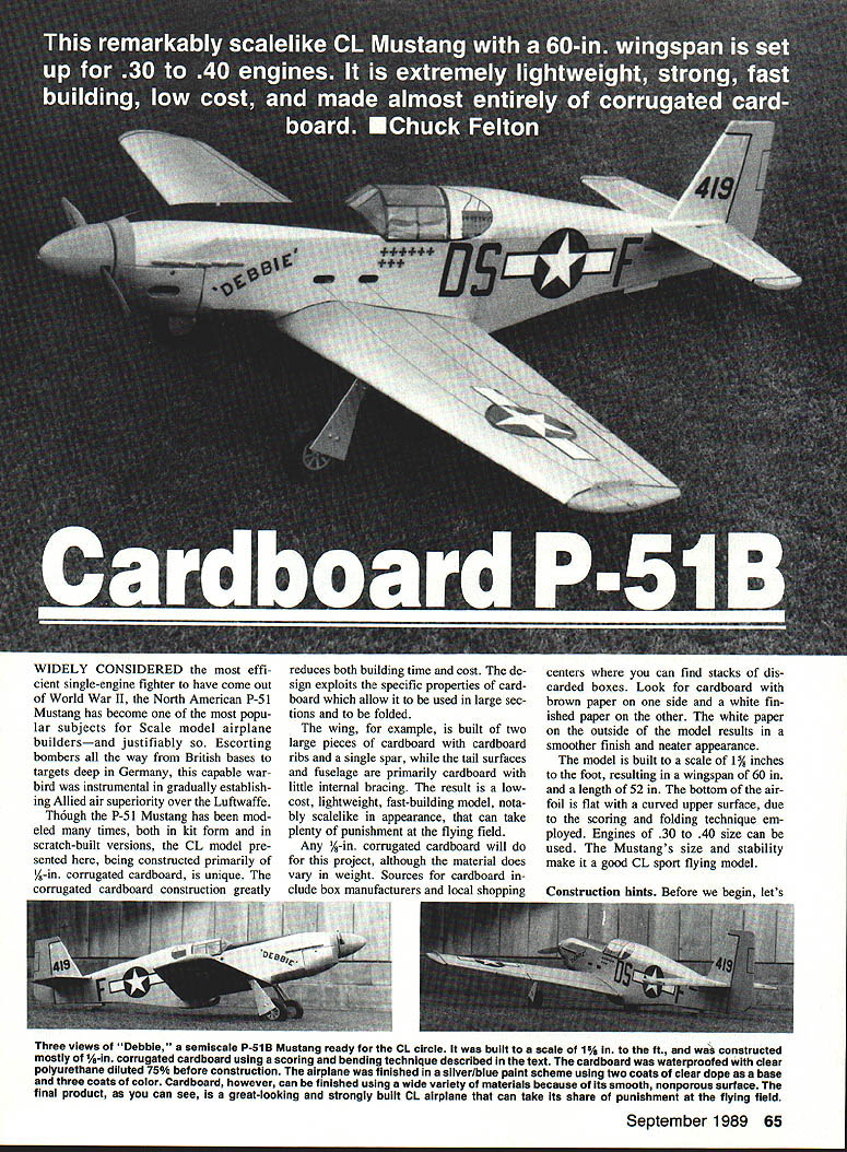
This remarkably scalelike CL Mustang with a 60-in. wingspan is set up for .30 to .40 engines. It is extremely lightweight, strong, fast building, low cost, and made almost entirely of corrugated cardboard. — Chuck Felton
Widely considered the most efficient single-engine fighter to have come out of World War II, the North American P-51 Mustang has become one of the most popular subjects for scale model airplane builders—and justifiably so. Escorting bombers all the way from British bases to targets deep in Germany, this capable warbird was instrumental in gradually establishing Allied air superiority.
Though the P-51 Mustang has been modeled many times, both in kit form and in scratch-built versions, the CL model presented here, being constructed primarily of 1/8-in. corrugated cardboard, is unique. The corrugated cardboard construction greatly reduces both building time and cost. The design exploits the specific properties of cardboard which allow it to be used in large sections and to be folded.
The wing, for example, is built of two large pieces of cardboard with cardboard ribs and a single spar, while the tail surfaces and fuselage are primarily cardboard with little internal bracing. The result is a low-cost, lightweight, fast-building model, notably scalelike in appearance, that can take plenty of punishment at the flying field.
Any 1/8-in. corrugated cardboard will do for this project, although the material does vary in weight. Sources for cardboard include box manufacturers and local shopping centers where you can find stacks of discarded boxes. Look for cardboard with brown paper on one side and a white finished paper on the other. The white paper on the outside of the model results in a smoother finish and neater appearance.
The model is built to a scale of 1-1/2 in. = 1 ft., resulting in a wingspan of 60 in. and a length of 52 in. The bottom of the airfoil is flat with a curved upper surface, due to the scoring and folding technique employed. Engines of .30 to .40 size can be used. The Mustang's size and stability make it a good CL sport flying model.
Construction hints
Before beginning, study the three views. The semi-scale P-51B Mustang built for CL circle is at a scale of 1-1/2 in. = 1 ft. and was constructed mostly of 1/8-in. corrugated cardboard using the scoring/bending technique described below. The cardboard was waterproofed with diluted clear polyurethane before construction. The airplane was finished in a silver/blue paint scheme using two coats of clear dope as a base and three coats of color.
Cardboard can be finished using a wide variety of materials because its smooth, nonporous surface produces a final product that can be a great-looking, strongly built CL airplane that can take its share of punishment at the flying field.
Glue
- Use water-based glue such as white glue or Titebond.
- Contact cement is not recommended since parts can shift when gluing surfaces.
Folding / Scoring
- Fold lines are made by scoring with a screening tool available at hardware stores; it consists of a handle and a 1-1/2-in. radius wheel. Run the wheel along a straightedge at the fold line.
Waterproofing
- Thoroughly mix 25% clear polyurethane with 75% paint thinner (the thinner can be the cheapest hardware-store variety).
- Brush the mixture liberally onto the cardboard sheet and allow to dry for 48 hours before cutting parts. This adds no appreciable weight and renders the cardboard waterproof. Treated cardboard cuts and divides sharply and cleanly.
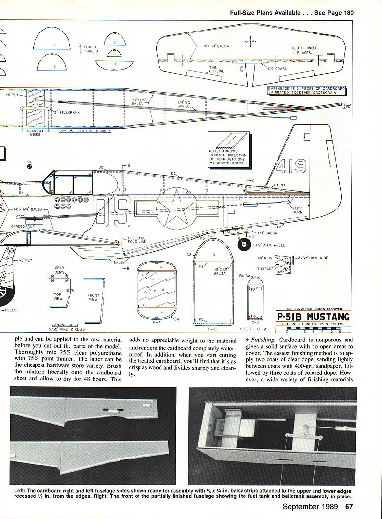
Full-size plans available — see page 180.
Finishing
- Cardboard is essentially nonporous and provides a solid surface with no open areas to cover.
- The suggested finishing method is two coats of clear dope, sanding lightly between coats with 400-grit sandpaper, followed by three coats of colored dope.
- Coverings such as Solarfilm, MonoKote, and vinyl paper can also be used; if using these coverings, do not dope the surface, which will result in a better bond.
Paper tape
- All seams, joints, and exposed edges of the model are covered with strips of gummed paper tape. Obtain a 1-in.-wide roll from a stationery store. Cut a thin strip to length, dip it in water, and smooth it over the seam to seal raw edges.
Construction
Cut out all cardboard and wood parts using the template outlines. Be sure to note the direction of the corrugations. Score and fold cardboard parts as indicated on the plans.
Empennage
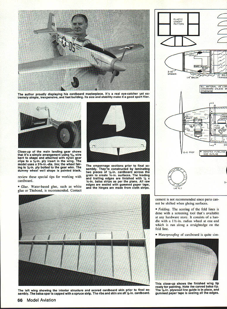
- The fin, rudder, stabilizer, and elevator are each made from two pieces of 1/8-in. cardboard laminated together across the grain to create 1/4-in.-thick surfaces.
- Add 1/8 x 1/4-in. balsa strips to the fin leading edge and round it off. Add 1/8 x 1/4-in. balsa strips to the stabilizer leading and trailing edges and round off.
- Glue the elevators to a 1/4-in. dowel. Add 1/8 x 1/4-in. balsa to the remainder of the elevator leading edge and round off.
- Seal raw edges with gummed paper tape. Hinge the elevators to the stabilizer with cloth strips at four places.
Wing
- Make the spar by capping each 1/4-in. balsa spar half with a 1/4 x 1/4-in. spruce strip on the top and bottom. Join the spar halves together with 1/8-in. ply front and rear at the centerline.
- Glue the 1/8-in. ply gear mount into each wing panel. Glue the right side of the wing spar onto the right-hand wing panel (W9). Fit and glue all cardboard ribs into place on the right wing. Add a cardboard doubler over the ply gear mount between ribs W3 and W4. Glue a one-ounce weight to the right wing tip.
- Glue the left wing panel to the left spar in a similar fashion. Add the ribs and gear doubler to the left wing. Apply glue to the top of the wing spar, the top of the ribs, and the trailing edge of the wing. Fold the top wing surface down and pin it securely in place until dry.
- Add the balsa tips to the wing. Make a line guide from 1/8-in. ply. Cut a slot in the left wing balsa tip and glue the line guide in place. Cover the trailing edge and all seams with gummed paper tape.
Fuselage
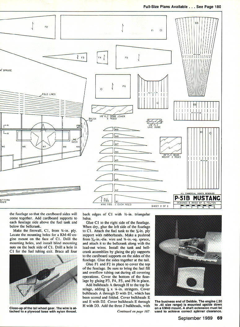
- The fuselage sides are outlined on the drawing. Apply 1/8 x 1/4-in. balsa strips to the upper and lower edges of each side, recessed 1/8 in. from the edges as shown in the fuselage side view. Bevel the strips at the aft end so the cardboard sides will come together. Add cardboard supports to each fuselage side above the fuel tank and below the bellcrank.
- Make the firewall, C1, from 1/4-in. ply. Locate the mounting holes for a KM-40 engine mount on the face of C1, drill the mounting holes, and install blind mounting nuts on the back side of C1. Drill a hole in C1 for the fuel tubing exit. Brace all four back edges of C1 with 1/2-in. triangular balsa.
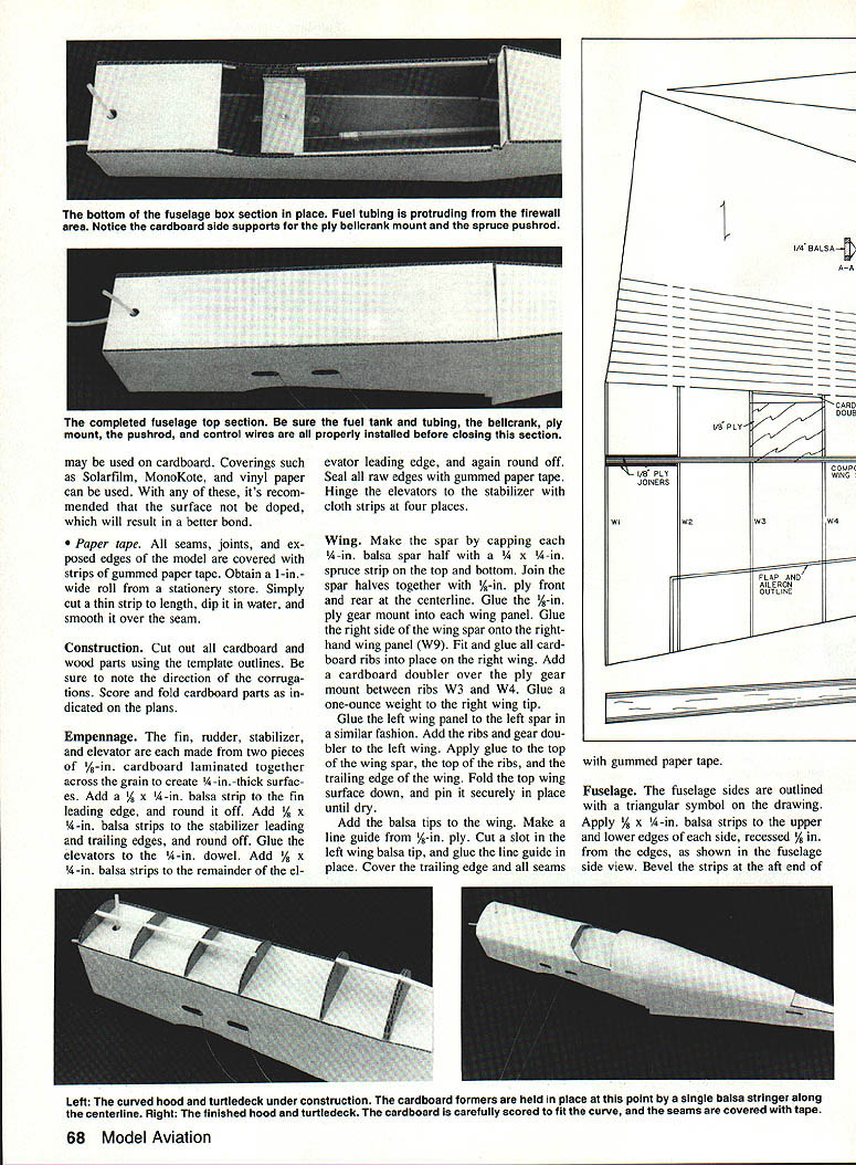
- Glue C1 to the right side of the fuselage. When dry, glue the left side of the fuselage to C1. Attach the fuel tank to the 1/2-in. ply support with rubber bands. Make a pushrod from 3/32-in.-dia. wire and 1/8-in.-sq. spruce, and attach it to the bellcrank along with the lead-out wires. Install the tank and bellcrank assemblies by gluing the ply supports to the cardboard supports on the sides of the fuselage. Glue the sides together at the tail.
- Glue F1 and F2 in place to cover the top of the fuselage, bringing the fuel fill and overflow tubing out during all covering operations. Cover the bottom of the fuselage by gluing F3, F4, F5, and F6 in place.
- Add bulkheads A through H to the top fuselage and add 1/8 x 1/4-in. stringers. Cover bulkheads A through D with D1, which has been scored and folded. Cover bulkheads E and F with D2. Cover bulkheads G and H with D3. Add a stringer to the forward bottom fuselage and cover with D4. Add the balsa sheet piece to the bottom of F5, rounding off the edges as shown in the plans.
Cowl and engine installation
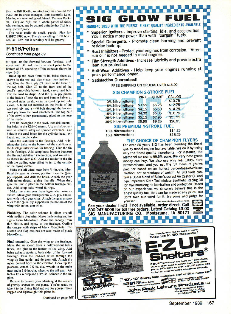
- Build up the cowl from 1/8-in. balsa sheet as shown in the top and side views, then hollow it out. Glue the 1/4-in. ply C2 piece to the front of the top half. Glue C3 to the front end of the cowl's removable bottom. Sand, carve, and hollow the cowl top to shape. Add 1/8-in. ply pieces to the inside of both the top and bottom halves at the cowl sides. Install a blind nut on the inside of the cowl top to hold the cowl to the bottom cowl ply for cowl attachment. The top half of the cowl is then permanently glued to the nose of the model.
- Test-fit the engine in the cowl, then drill mounting holes in the KM-40 mount. Use a shaft extension to achieve adequate spinner clearance. Cut holes in the cowl block for the cylinder head, exhaust, and needle valve.
Tail and gear
- Glue the stabilizer to the fuselage. Add 1/2-in. triangular balsa to the bottom of the stabilizer at the fuselage intersection for bracing. Glue the fin to the fuselage. Add scrap balsa bracing between the fin and stabilizer intersection and round off as shown in the plans. Add the rear fuselage pieces with the trailing edge offset 1/8 in. to the outside of the flying circle.
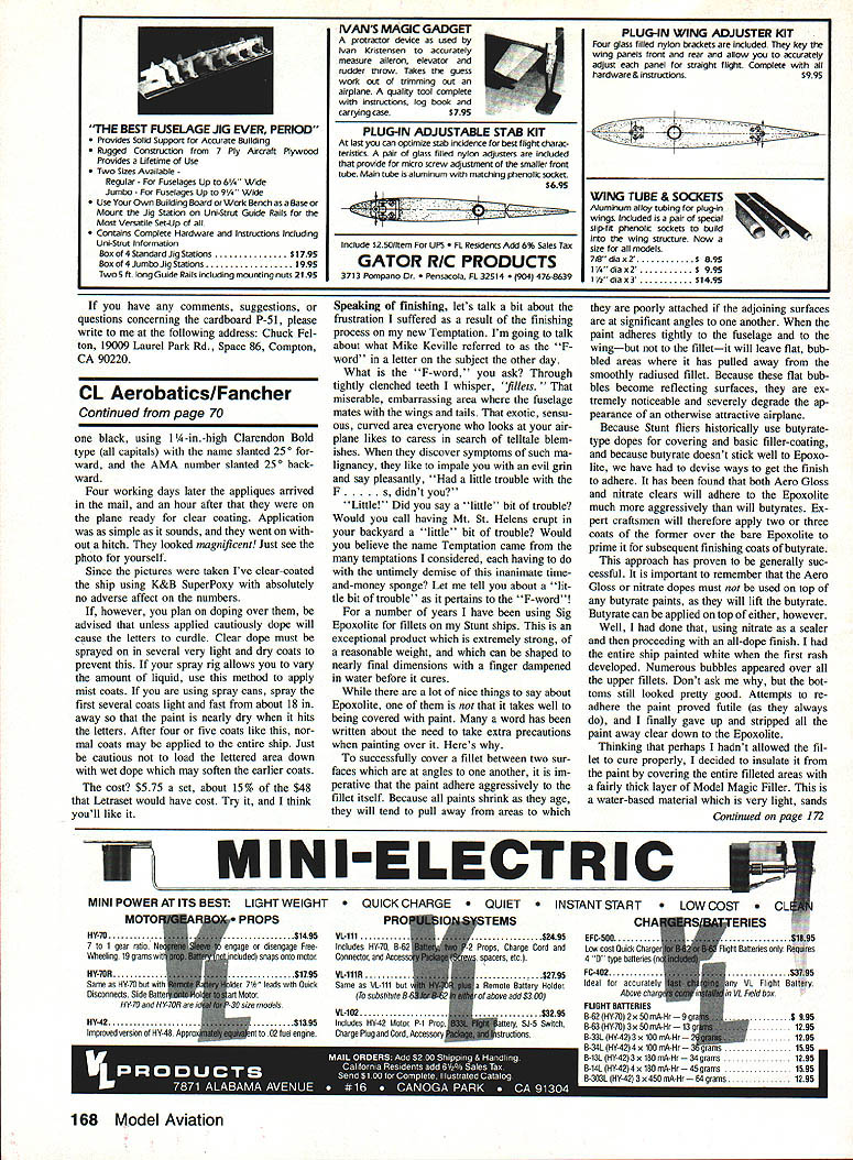
- Make the tailwheel gear from 3/32-in.-dia. wire. Bend the gear as shown, position it on the 1/4-in. ply support, and drill the holes. Attach the gear with nylon thread and glue liberally. When dry, glue the unit in place in the bottom fuselage cutout. Add scrap balsa wheel fairings.
- Make the main gear from 3/32-in.-dia. wire as shown. Make gear fairings from 1/8-in. ply and attach with nylon gear clips. Attach the gear assemblies to the 1/8-in. ply supports in the bottom of the wing with nylon gear clips.
Finishing
- The color scheme is silver overall with medium blue trim. Make the lettering and insignia from MonoKote.
- Make the canopy from thin plastic and epoxy it to the fuselage. Outline the canopy with strips of black MonoKote. The aileron and flap outlines are also made of black MonoKote.
- Cover any remaining seams and edges with gummed paper tape and touch up paint as required.
Final assembly
- Glue the wing to the fuselage.
- Make the air scoop from a hollowed-out balsa block and glue it to the bottom of the wing.
- Add balsa exhaust stacks to both sides of the forward fuselage. Pass the lead-out wires through the wing tip line guide and tie them off. Attach the nylon control horn to the elevator and lock up the pushrod.
- Attach 3/8-in.-dia. wheels to the main gear and a 1/2-in.-dia. wheel to the tail gear. Attach a 12 x 6 prop and a 3-1/2-in. spinner to the engine.
Be sure to balance your Mustang at the center of gravity shown in the plans. You're ready to take it to the flying field and see for yourself how rugged and lightweight this plane is.
Transcribed from original scans by AI. Minor OCR errors may remain.

