
Cardinal Classic
By Dave Haught
Maybe it's happened to you, too. You get an idea for a model, and before long it's claimed a place in your mind. You sketch it on napkins during boring business meetings, maybe even contemplate its flying pattern and winning the Nationals. Such dreams are tenacious; they linger on, until—usually years later—you eventually make them real.
So it was with the Cardinal Classic. A singular mix of proven designs—the Miss Los Angeles, Spiezo Sport Tu-holer, Kinner Sportster, and my favorite classic stunter, the Oriental—this bright red beauty with the flame-licked nose inhabited my imagination for years before I finally got round to building it. Seven years, in fact, and a few false starts.
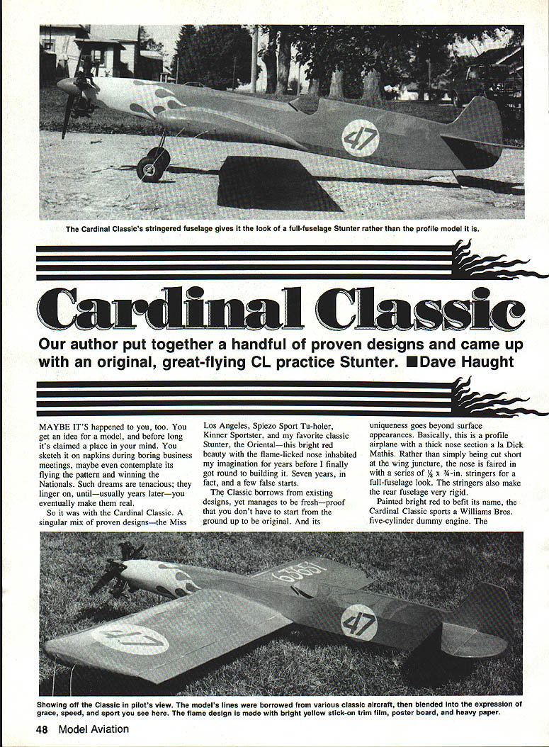
The Classic borrows from existing designs, yet manages to be fresh—proof that you don't have to start from the ground up to be original. Basically, this is a profile airplane with a thick nose section à la Dick Mathis. Rather than simply being cut short at the wing juncture, the nose is faired in with a series of 1/4 x 3/4-in. stringers for a full-fuselage look. The stringers also make the rear fuselage very rigid.
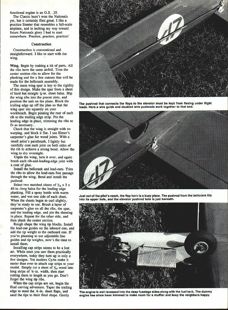
Painted bright red to befit its name, the Cardinal Classic sports a Williams Bros. five-cylinder dummy engine. The functional engine is an O.S. .35.
Construction
Construction is conventional and straightforward. I like to start with the wing.
Wing
Begin by making a kit of parts. All the ribs have the same airfoil. Trim the center section ribs to allow for the planking and for a few cutouts that will be made for the bellcrank assembly.
The main wing spar is key to the rigidity of this design. Make the spar from a sheet of hard but straight 3/16-in. sheet balsa. Slip the wing ribs into the precut slots, and position the unit on the plans. Block the trailing edge up off the plan so that the wing spar sits squarely on your workbench. Begin pinning the rear of each rib to the trailing edge strip. Pin the leading edge in place, trimming the ribs to fit as necessary.
Check that the wing is straight with no warping, and block it flat. I use Elmer's carpenter's glue for wood joints. With a small artist's paintbrush, lightly but carefully coat each joint on both sides of the rib to achieve a strong bond. Allow the wing to dry overnight.
Unpin the wing, turn it over, and again brush each rib-and-leading-edge joint with a coat of glue.
Install the bellcrank and lead-outs. Trim the ribs to allow the lead-outs free passage through the wing. Bend and install the pushrod.
Select two matched sheets of 1/16 x 3 x 48-in.-long balsa for the leading edge planking. Fill a spray bottle with warm water, and wet one side of each sheet. When the sheets begin to curl slightly, they're ready to use. Brush a layer of carpenter's glue on all the ribs, the spar, and the leading edge, and pin the sheeting in place. Repeat for the other side, and then plank the center section.
Rough-shape the wing tip blocks. Install the lead-out guides on the inboard one, and add the tip weight to the outboard one. If you're planning to use adjustable line guides and tip weights, now's the time to install them.
Installing cap strips seems to be a lost art. While once you saw them practically everywhere, today they turn up in only a few designs. Yet modern CAs make it easier than ever to attach cap strips to your model. Simply cut a sheet of 1/16-in. wood into long strips of 1/4-in. width, then start cutting them to length as you go. Don't forget the wing tip ribs.
When the cap strips are set, begin the final carving adventure. Taper the trailing edge to meet the 1/4-in. sheet flaps, and sand the tips to their final shape. Gently round the leading edge sheets to a smooth radius.
Cut the flaps from medium-weight 1/8-in. sheet that is straight and true. Sand in whatever taper you desire, and round the leading and trailing edges.
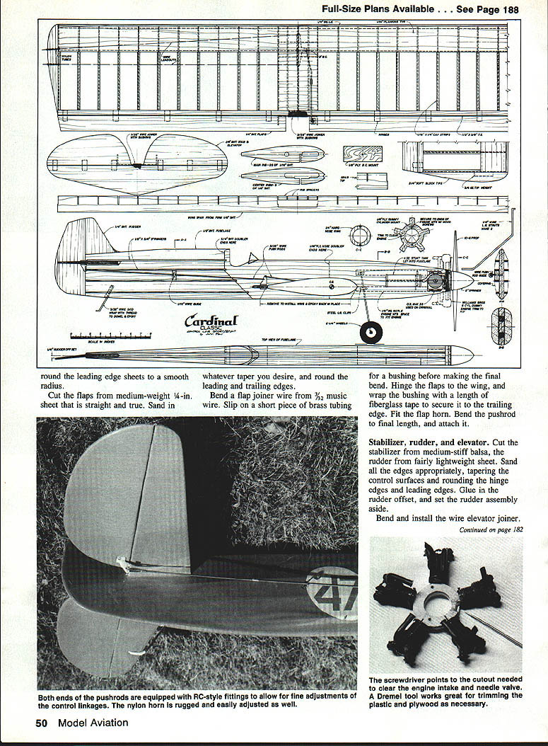
Bend a flap joiner wire from 3/32 music wire. Slip on a short piece of brass tubing for a bushing before making the final bend. Hinge the flaps to the wing, and wrap the bushing with a length of fiberglass tape to secure it to the trailing edge. Fit the flap horn. Bend the pushrod to final length, and attach it.
Stabilizer, rudder, and elevator
Cut the stabilizer from medium-stiff balsa and the rudder from fairly lightweight sheet. Sand all the edges appropriately, tapering the control surfaces and rounding the hinge edges and leading edges. Glue in the rudder offset, and set the rudder assembly aside.
Bend and install the wire elevator joiner. Don't forget to bush it with a length of brass tube as you did the flap joiner. Install the hinges, and join the elevator to the stabilizer. Wrap the tube bushing with a layer of glass cloth as reinforcement. Give the assembly a final sanding.
Fuselage
This phase goes quickly. Cut the core profile from a medium-lightweight sheet of 1/2-in. balsa. Cut out the engine mount, fuel tank, stabilizer, and wing locations. Make the two plywood nose doublers, and fit them on the fuselage core with the hardwood engine mounts. Once you have a good fit, glue the works together with wood glue and clamp it overnight.
While this assembly is drying, bend the landing gear and the tail skid. Wrap the tail skid wire to a length of hardwood dowel, and drill a hole in the rear fuselage to accommodate the skid and its dowel. Make the hole slightly larger in diameter than the dowel. Attach the skid-and-dowel with epoxy or wood glue.
When the fuselage is dry, trim the plywood as necessary in order to set the engine in place. Drill the mounting holes, and install the blind mounting nuts in the rear. At the same time, drill the holes for the landing gear mounting straps and install the straps and gear. Secure the nuts with a drop of solder. If you've ever been caught with your face red because the nuts backed out, you'll know why I suggest that.
Make the thick fuselage doublers from lightweight 3/16-in. sheet. Cut them to shape, and glue them in place. Carve them to a pleasing contour when dry. Taper can be kept to a minimum as the doublers approach the trailing edge of the wing, since the stringers take over the job at that point.
Select several fairly firm strips of 1/8 x 3/8-in. balsa for the stringers. Begin with the top stringer. This forms the top of the stabilizer's nose slot, so make sure it's properly aligned. Fit a short length of stringer under the stabilizer slot to anchor the covering, and fit a small piece at the leading edge of the stabilizer.
Install the remaining stringers. Make a block to support the pushrod guide, and install it between the second and third stringers. Allow the stringers to dry, then trim them to taper back to the rudder post as shown in the plan top view. At the other end of the fuselage, carve the fuel tank well and install the fuel tank. Because of the thickness of the doublers, the filler vents and vent tubes on the tank may need either to be relocated or to be extended to clear the fuselage.
If you're using the dummy five-cylinder engine, build it now. I used the Williams Bros. kit cylinders, mounting them to the plywood cylinder mounts as shown on the plan. This works very well if the engine mounts at the nose with long wood screws, so that the crank engine can be removed if desired.
So far the mounting system has worked fine. During an unexpected inverted landing, the top cylinder popped off but the plywood mounting tab stayed intact. The dummy engine has presented no other problems during two seasons of practice flying. In fitting the cylinders, don't forget to trim away access to the needle valve and fuel lines for the functional engine. To get just a bit more clearance, I eliminated the forward-facing spark plug wires and the spark plugs from the dummy engine.
Slip the elevator and stabilizer into the slot at the rear of the fuselage. Make sure it's properly aligned with the fuselage, and glue it on. Add the rudder.
Take your time fitting the wing to the fuselage. When you're happy with it, glue it securely with slow-drying epoxy.
Go over the entire model with a final sanding, checking for areas that need to be filled or adjusted. Once that's done, the airplane is ready for covering.
Covering and finishing
Since the Cardinal was intended as a practice ship, I wanted a low-investment finish. I selected bright red MonoKote and enhanced it with an even brighter yellow trim sheet.
I wiped a light coat of epoxy into the wood around the engine area, then sanded it later to make it fuelproof. The engine cylinder mount was painted red to match the covering.
I made the flame design as follows: After drawing the pattern on a sheet of heavy paper, I cut two sheets of stick-on trim film to rough size. Placing a sheet of poster board on the building board, I taped down the first sheet of trim film color side up, taped the second sheet color side down on top of the first, then taped the pattern over all. I used a sharp new #11 X-Acto blade to cut the design out. By pressing down hard, I was able to cut all three layers (the pattern and both films) at once. I placed the flames carefully on the fuselage, then rubbed out all the bubbles and wrinkles. The effect is stunning.
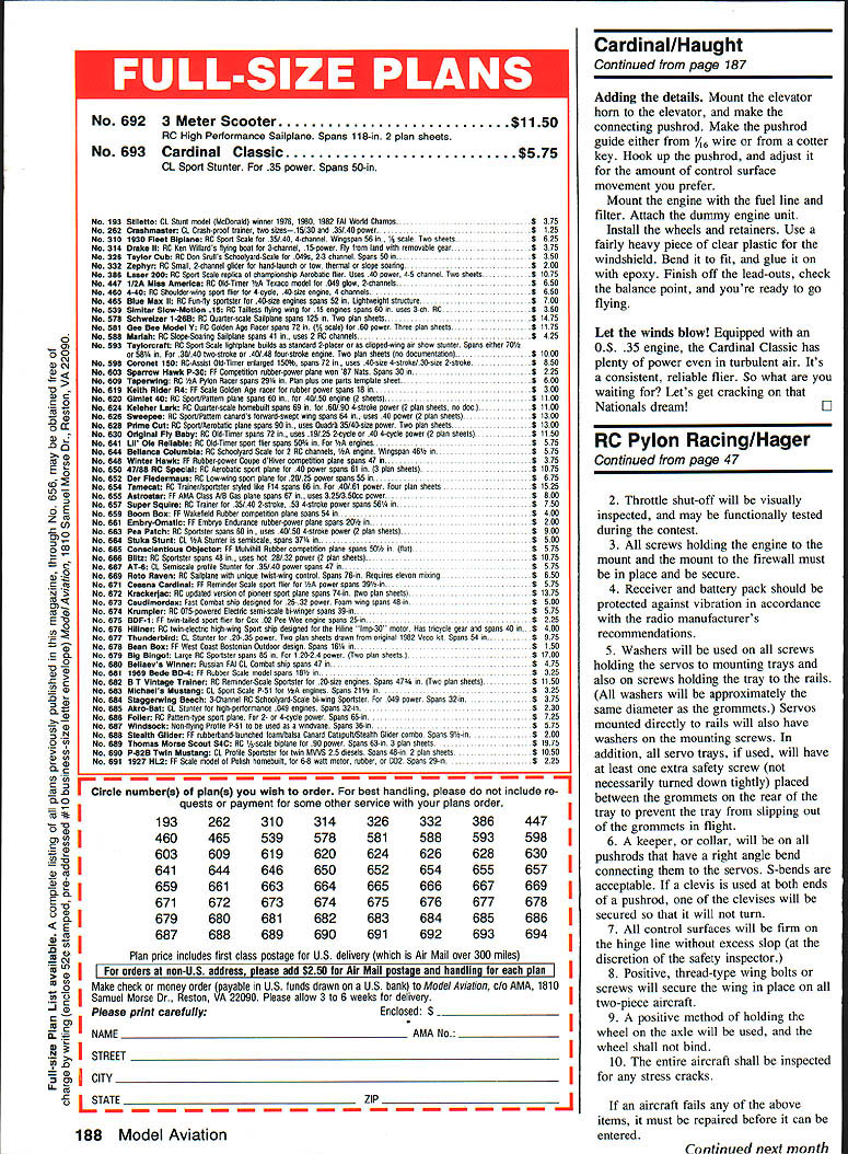
Full-size plans available. See page 188.
Adding the details
Mount the elevator horn to the elevator, and make the connecting pushrod. Make the pushrod guide either from 1/16-in. wire or from a cotter key. Hook up the pushrod, and adjust it for the amount of control surface movement you prefer.
Mount the engine with the fuel line and filter. Attach the dummy engine unit. Install the wheels and wheel pants. Use a fairly heavy piece of clear plastic for the windshield. Bend it to fit, and glue it on with epoxy. Finish off the lead-outs, check the balance point, and you're ready to go flying.
Let the winds blow! Equipped with an O.S. engine, the Cardinal Classic has plenty of power even in turbulent air. It's a consistent, reliable flier. So what are you waiting for? Let's get cracking on that Nationals dream!
Transcribed from original scans by AI. Minor OCR errors may remain.

