

The Case for 180-Degree Servos
Richard Carignan
Introduction
Today's radio-control servos have reached a remarkable degree of function, versatility, and reliability at low cost. They are available in a variety of sizes and output torque levels to satisfy the requirements of just about any R/C application.
Except for special and fairly expensive servos used for sailboat applications, these devices have rotary outputs that turn ±45°, covering a 90° arc. This article describes how, with a modification that increases servo arm rotation from ±45° to ±90° (180° total), more actuating force can be obtained from servos at the expense of reduced transit speed. This modification can either be made inside the servo electronics or implemented as an interface device between the receiver and the servo.
In applications where reduced transit time is not a concern, a 180° servo can perform these functions using a smaller servo size, thereby saving weight and cost. An additional advantage is the locking action and very high output force at the servo endpoints. A method of servo modification to achieve 180° is described below.
Typical Servo Operation (90° output)
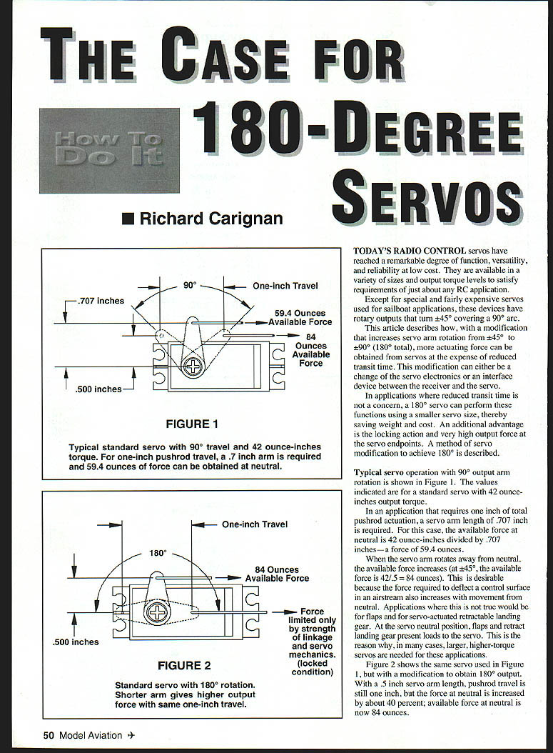
Typical servo operation with 90° output arm rotation is shown in Figure 1. The values indicated are for a standard servo with 42 ounce‑inches output torque.
- In an application that requires 1.00 inch of total pushrod actuation, a servo arm length of 0.707 inch is required. For this case, the available force at neutral is 42 ounce‑inches divided by 0.707 inches — a force of 59.4 ounces.
- When the servo arm rotates away from neutral, the available force increases. At ±45°, with an effective arm length of 0.5 inch, the available force is 42 / 0.5 = 84 ounces. This is desirable because the force required to deflect a control surface in an airstream also increases with movement from neutral.
- Applications where this is not true include flaps and servo‑actuated retractable landing gear. At the servo neutral position, flaps and retractable landing gear present loads to the servo. This is why, in many cases, larger, higher‑torque servos are needed for these functions.
Figure 2 shows the same servo used in Figure 1 but modified to obtain 180° output. With a 0.5 inch servo arm length, pushrod travel is still 1.00 inch, but the force at neutral is increased by about 40 percent; available force at neutral is now 84 ounces.
How the 180° Modification Works
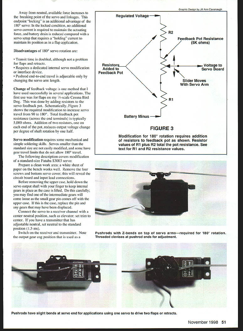
Figure 3 shows the required modification to increase servo travel from 90° to 180°. Total feedback potentiometer resistance across the end terminals is typically 5,000 ohms. Addition of two resistors across the end terminals of the pot reduces the output voltage change per degree of shaft rotation by half, effectively doubling servo travel for the same input pulse width range.
Advantages and Disadvantages
Advantages:
- Greater available actuating force at neutral, allowing use of a smaller servo for the same load.
- Strong locking action at the endpoints; in the locked condition, no additional servo current is required to maintain the actuating force, reducing battery drain compared with a servo setup that requires a continuous holding current (as in flap applications).
Disadvantages:
- Transit time is doubled, although this is usually not a problem for flaps and retracts.
- Requires a dedicated internal servo modification or an external interface device.
- Pushrod end‑to‑end travel is adjustable only by changing the servo arm length.
Tools and Preparation
Servo modification requires some mechanical and basic soldering skills. Some smaller servos are easily modified; others have gear travel limits that will not allow 180° travel. The following instructions cover modification of a standard-size Futaba S3003 servo.
Prepare a clean work area (a white sheet of paper on the bench works well). Have a small jeweler's screwdriver, long-nose pliers, small wedges or thin metal chisels for releasing pot catches, wire cutters, and a soldering iron ready. Typical components include two 1/4-watt resistors (values selected as described below).
Disassembly and Initial Checks
- Remove the four screws on the bottom servo cover; this will reveal the circuit board and the input lead connections. Before removing the upper case, hold down the servo output shaft with a finger to keep the internal gears in place. As the case is lifted carefully you may find intermediate gears will come loose and a small gear pin may come out of the upper case. If a pin comes out, replace it and note that some gears may have been displaced.
- Connect the servo to the receiver channel and center the neutral position (such as elevator trim) on the transmitter. If the transmitter has an adjustable neutral, set the neutral to the standard position. Switch the receiver and transmitter on. Note the output gear cog position used.
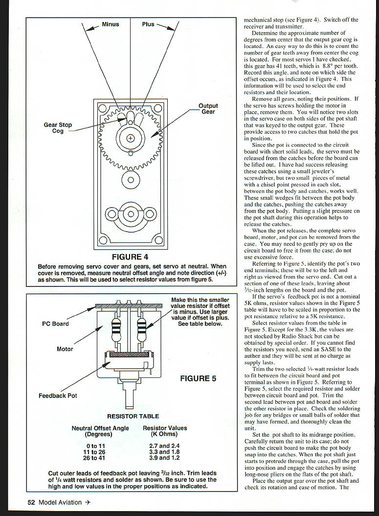
- Place the output gear over the pot shaft and check its rotation and ease of motion. Note the mechanical stop (see Figure 4). Switch off the receiver and transmitter.
- Determine the approximate number of degrees from center that the output gear cog is located. An easy way to do this is to count the number of gear teeth away from center the cog is located. For most servos checked, this gear has 41 teeth, which is 8.8° per tooth. Record this angle and note on which side the offset occurs, as indicated in Figure 4. This information will be used to select the end resistors and their location.
- Remove all gears, noting their positions. If the servo has screws holding the motor in place, remove them. You will notice two slots in the servo case on both sides of the pot shaft that is keyed to the output gear. These provide access to two catches that hold the pot in position.
Because the pot is connected to the circuit board with short solid leads, the servo must be released from the catches before the board can be lifted out. Small wedges (two small pieces of metal with a chisel point pressed in each slot, between the pot body and catches) work well. These small wedges fit between the pot body and the catches, pushing the catches away from the pot body. Putting slight pressure on the pot shaft during this operation helps to release the catches.
When the pot releases, the complete servo board, motor, and pot can be removed from the case. You may need to gently pry up on the circuit board to free it from the case; do not use excessive force.
Selecting and Installing Resistors
- Referring to Figure 5, identify the pot's two end terminals; these will be to the left and right as viewed from the servo end. Cut out a section of one of these leads, leaving about 3/32 inch lengths on the board and the pot.
- If the servo's feedback pot is not a nominal 5K ohms, resistor values shown in the Figure 5 table will have to be scaled in proportion to the pot resistance relative to 5K ohms.
- Select resistor values from the table in Figure 5. Except for the 3.3K, the values may not be stocked at local hobby stores but can often be obtained by special order.
- Trim the two selected 1/4-watt resistor leads to fit between the circuit board and pot terminal as shown in Figure 5. Solder one resistor between the circuit board and the pot terminal on one side, and solder the other resistor in place on the opposite side. Check the soldering job for any bridges or small balls of solder that may have formed, and thoroughly clean the unit.
Note: Addition of these two resistors across the pot end terminals reduces the slope of the pot output versus shaft angle, effectively doubling the angular travel for a given input pulse range.
Reassembly and Testing
- Set the pot shaft to its midrange position. Carefully return the unit to its case; do not push the circuit board to make the pot body snap into the catches. When the pot shaft just starts to protrude through the case, pull the pot into position and engage the catches by using long-nose pliers on the flats of the pot shaft.
- Place the output gear over the pot shaft and check its rotation and ease of motion. The gear cog should be positioned pointing to the case end, as in Figure 4. Reinstall the remaining gears, pins, and case covers.
- Connect the servo to the receiver as before and turn on the transmitter. The servo should respond to control stick movement.
- With the controlling channel at neutral, temporarily attach a servo output arm so you can observe the angular output-arm rotation. Move the control stick to see if you are getting 180° rotation. If the servo shaft moves 180° without hitting stops, you are finished. If not, it could be that the servo drive gear is hitting its stop; you may need to adjust transmitter travel.
- Listen carefully: if the servo is hitting the internal stop, you will hear the servo hum as it tries to go beyond the stop. The servo will also be drawing high stall current in this condition.
Mechanical Setup
Mechanical setup of the 180° servo requires use of a Z-bend on the servo end of the pushrod that enters the servo arm from the top side (see Figure 6). A threaded clevis should be used at the other pushrod end to provide adjustment. For an application using one servo to drive two flaps or two retracts, the Z-bend ends of the pushrods must have a slight bend so the full 180° rotation can be obtained (see Figure 7).
Multiple-Servo Arrangements
- Use a Y connector when using two servos for the same function, such as left and right flaps.
- In some cases where two servos are used for a single application, it may be necessary to reverse the rotation of one servo to obtain the desired actuation of both devices. This can be achieved by:
- a servo modification,
- purchase of a reversed servo,
- an interface circuit available from various suppliers, or
- making your own reverser (see MA, May 1997 article by Brent Dane).
Interface Devices and Alternatives
An interface device between the receiver and servo that increases signal pulse length rate‑of‑change is another method to get 180° servo rotation.
A search of the U.S. Patent Office site turned up a February 1997 patent on exactly this type of device based on microcontroller technology. The inventor is Walter S. Polan; he manufactures the unit called the Servo Genie servo extender, which also has a servo‑reversing option. He developed this device as part of his work in the movie special-effects industry. His company is Electrofex in Glendale, CA. The unit is available from Robbins Hobby, also in Glendale, CA.
Author / Contact
Roger Carignan 39 Glen Road Wilmington, MA 01887 rogercar@gis.net
Transcribed from original scans by AI. Minor OCR errors may remain.

