

Charles A. Bair, Jr.
THE CASE FOR THE CANARD
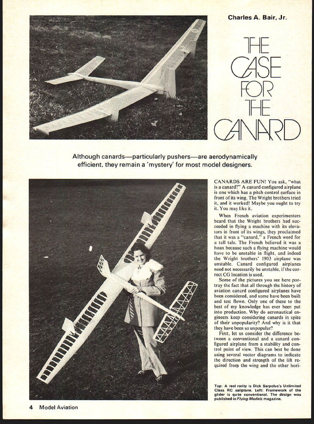
Although canards—particularly pushers—are aerodynamically efficient, they remain a 'mystery' for most model designers.
CANARDS ARE FUN! You ask, "what is a canard?" A canard configured airplane is one which has a pitch control surface in front of its wing. The Wright brothers tried it, and it worked! Maybe you ought to try it. You may like it.
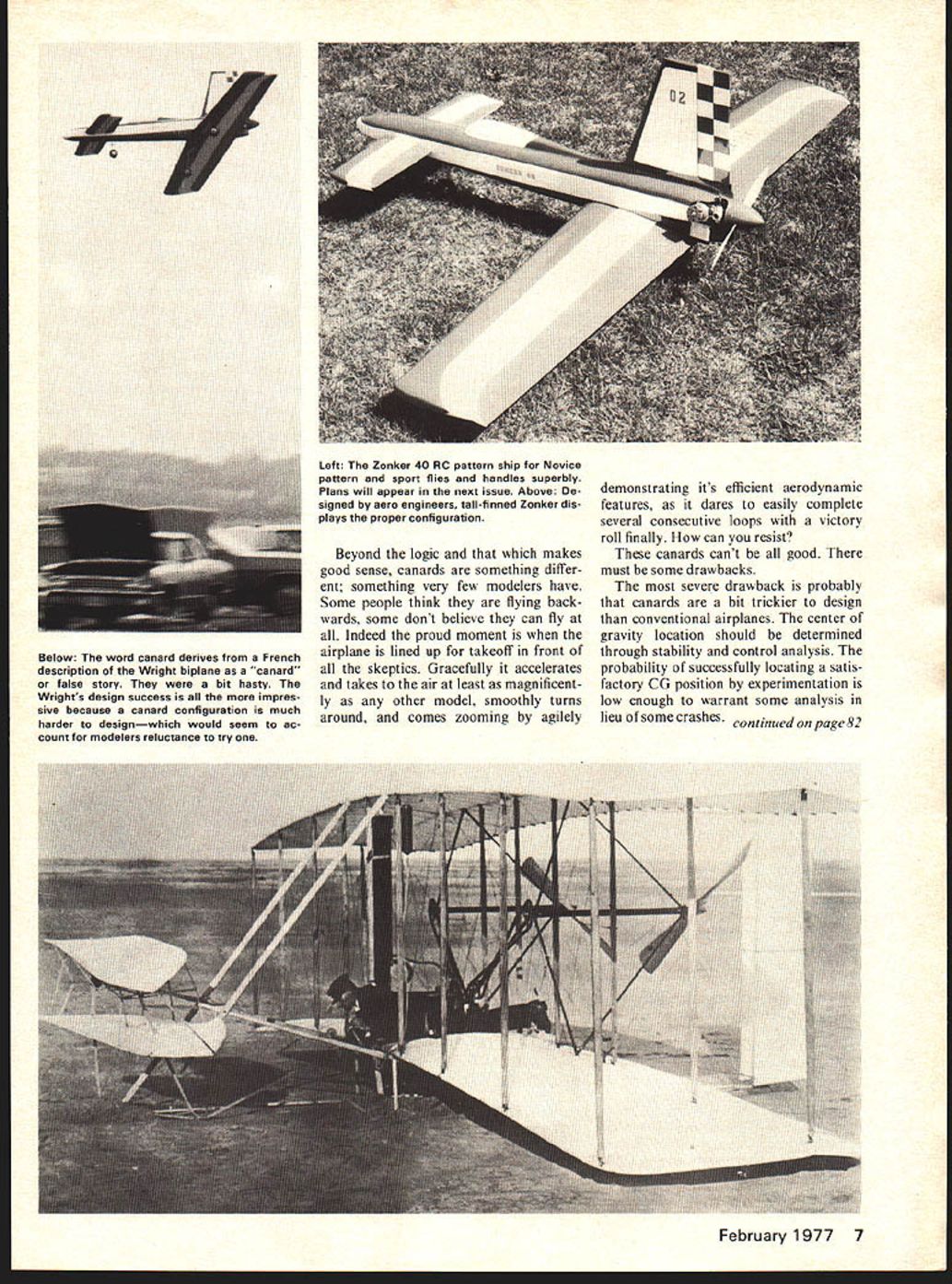
When French aviation experimenters heard that the Wright brothers had succeeded in flying a machine with its elevators in front of its wings, they proclaimed that it was a "canard," a French word for a tall tale. The French believed it was a hoax because such a flying machine would have to be unstable in flight, and indeed the Wright brothers' 1903 airplane was unstable. Canard configured airplanes need not necessarily be unstable, if the correct CG location is used.
Some of the pictures you see here portray the fact that all through the history of aviation canard configured airplanes have been considered, and some have been built and test flown. Only one of these to the best of my knowledge has ever been put into production. Why do aeronautical engineers keep considering canards in spite of their unpopularity? And why is it that they have been so unpopular?
First, let us consider the difference between a conventional and a canard configured airplane from a stability and control point of view. This can best be done using several vector diagrams to indicate the direction and strength of the lift required from the wing and the other horizontal surface. Whether tail surface or canard surface, different demands are made on the airplane. Remember, the amount of lift required of a flying surface will be indicated by the length and position of the lift vector. The position of the vector will be at the aerodynamic center (center of pressure) of the surface. In the vector diagrams for the equilibrium flight condition shown, the moments produced by the lift of the two lifting surfaces must balance about the CG location. We shall examine different possibilities.
A stable airplane on a change of angle of attack to a greater angle of attack must, of course, be controllable in pitch. A stable conventional airplane presents two possibilities, shown in Fig. 1 and 2. Note: the weight of the airplane shown is Mg (mass × acceleration due to gravity). Account must be taken of g turns, pull-ups, etc. If the airplane's center of gravity (CG) is at or forward of the neutral point the airplane will be stable; if the CG is aft of that point the airplane will be unstable and will handle in an undesirable fashion. Many model airplanes have met doom on the maiden flight due to disregard or lack of understanding of the very real CG limitations.
Fig. 1 shows a typical model CG location. Fig. 2 shows the situation with an aft CG location that is still far enough forward to remain stable. You will note immediately that with the CG forward of the center of pressure of the wing the tail must produce a downward lift in order to produce equilibrium. Horrors! Worse yet, to obtain greater amounts of lift the wing must be raised to a higher angle of attack, increasing the already undesirable tail downward lift. In addition, reducing the net lift of the total airplane (remember, there’s lift and there’s drag). For example, you actually pay a drag penalty to generate downward lift. Downward lift works against the wing. As a result, the wing is required to produce lift to make up the tail-down load — at the cost of yet more drag.
Would you believe model airplanes flown as just described can still be quite stable and probably handle nicely in gusty conditions?
Fig. 3 shows a canard-configured airplane with a typical CG. In this layout the canard provides positive lift ahead of the wing. Because the canard carries part of the lifting load, the wing’s lift vector and required wing angle of attack are reduced for the same total airplane lift. The moments produced by the canard and wing must balance about the CG in the same way as for a conventional tail/wing combination.
Remember that the amount of lift required from each flying surface will be indicated by the length of the lift vector. The position of the vector will be the aerodynamic center or center of pressure of each surface. Each vector diagram must be in equilibrium to maintain the flight condition shown; therefore, the moments produced by the lift of the two lifting surfaces must balance about the CG location. In addition to reducing the net lift of the total airplane, remember that where there's lift, there's drag. In this example we actually pay a drag penalty to generate downward lift which works against the wing! Result: the wing is required to produce more lift to make up for the tail-down load at the cost of yet more drag. Would you believe that most model airplanes fly just as described here? I will say that these airplanes are quite stable, and probably handle nicely in gusty conditions.
Fig. 2 shows a conventional airplane configuration with a CG location aft of the aerodynamic center of pressure of the wing, but forward of the airplane neutral point. If symmetric airfoils are used on the wing and horizontal stabilizer, such a situation is always possible. This is the way most competition pattern fliers balance their airplanes in the interest of good performance. In this situation both the wing and the horizontal stabilizer produce upward lift forces to keep the airplane in equilibrium.
However, as we investigate what is required to produce more lift, we find that we must decrease the lift of the horizontal stabilizer to increase the lift of the wing. It would be more desirable to increase the lift on all surfaces at once.
Let us consider the canard configured airplane. As we saw in the second case illustrated by Fig. 2, the wing and canard both produce upward lift for all flight conditions. The bonus for the canard configuration is that to raise the wing to a higher angle of attack, and hence obtain greater wing lift, the canard must produce more lift. Both the wing and canard are working together to increase the total airplane lift. This is one of the big payoffs in a canard configuration. First of all a greater amount of total lift is possible than for the examples of Fig. 1 and 2. Secondly, the lift of the canard is matched more closely to the lift of the wing. This second point provides for an aerodynamically efficient airplane through a wide range of angles of attack.
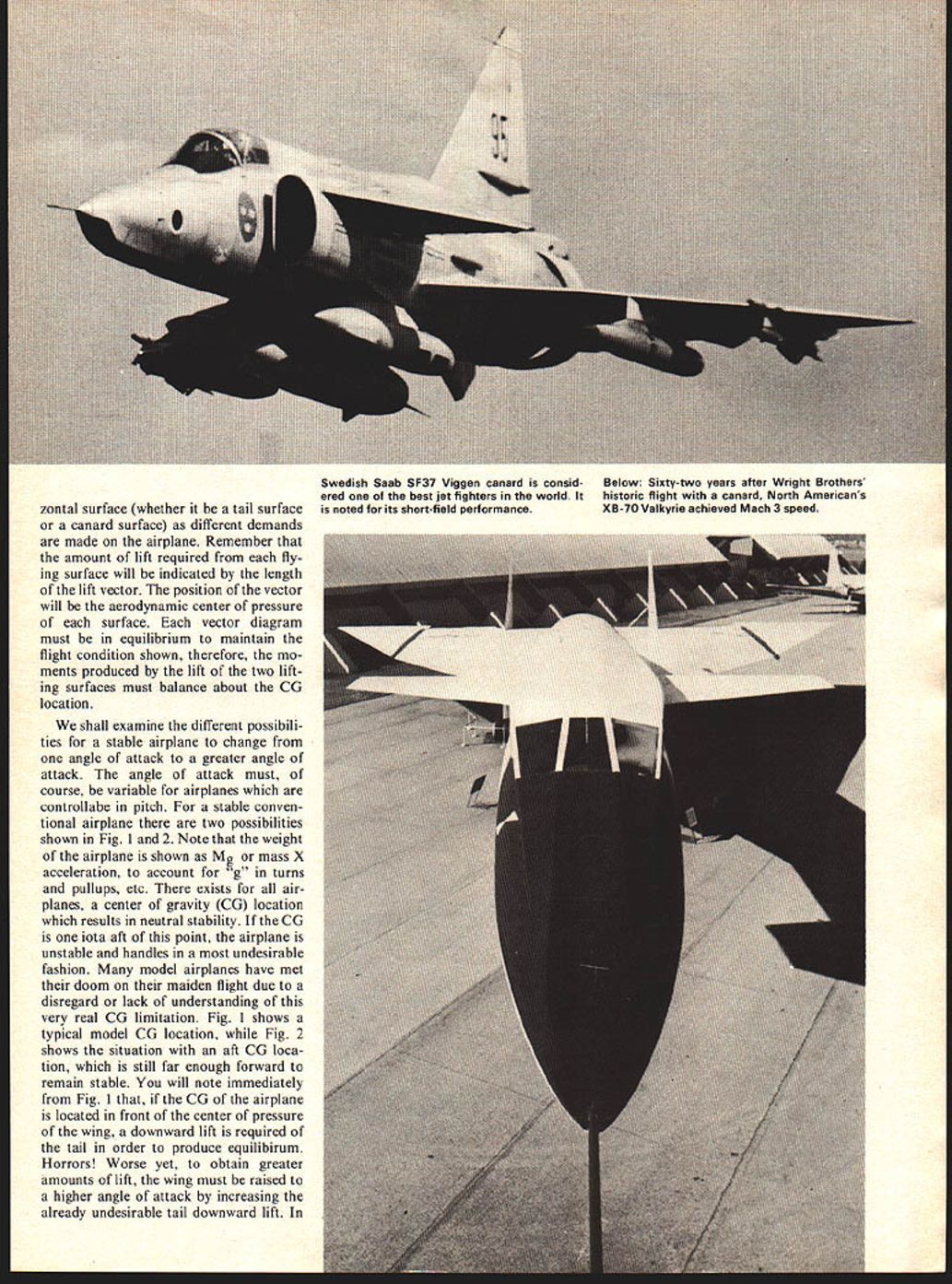
You now have an elementary understanding of why the Saab Viggen fighter airplane attains extraordinary short-field performance while retaining excellent high-speed capabilities. There are more advantages than aerodynamic efficiency too. Canard models lend themselves well to pusher configurations since the center of gravity needs to be pretty far aft of the nose in comparison to conventional models.
There are a number of reasons why a pusher configuration is more efficient than a conventional tractor arrangement. One of the biggest factors is that the high velocity turbulent propeller wash is all behind the airplane, thus allowing the airplane to fly in smoother air. Additionally, messy oil and engine exhaust are kept clear of the airplane. These are some of the sound, logical reasons for using canard-configured model airplanes. Beyond the logic and that which makes good sense, canards are something different; something very few modelers have. Some people think they are flying backwards, some don't believe they can fly at all. Indeed the proud moment is when the airplane is lined up for takeoff in front of all the skeptics. Gracefully it accelerates and takes to the air at least as magnificently as any other model, smoothly turns around, and comes zooming by agilely demonstrating its efficient aerodynamic features, as it dares to easily complete several consecutive loops with a victory roll finally. How can you resist?
These canards can't be all good. There must be some drawbacks.
The most severe drawback is probably that canards are a bit trickier to design than conventional airplanes. The center of gravity location should be determined through stability and control analysis. The probability of successfully locating a satisfactory CG position by experimentation is low enough to warrant some analysis in lieu of some crashes. Canards tend to exhibit some nasty stall and spin characteristics. Stalls and spins will not be encountered with normal control inputs. Another small drawback is that if the propeller is at the tail, the stall turn, a maneuver required in novice pattern, is a bit more difficult because the rudder effectiveness near stall speed is poor (the rudder is not in the propeller wash). With a little practice however good stall turns have been accomplished.
If a pusher configuration is used one must consider the small selection of pusher propellers available. A ball-bearing engine is required to withstand thrust toward the crankcase of the engine. Consideration can be given to engines which will run backwards by rotating the front plate of front-intake engines through 90°. If the engine is run backwards, a tractor propeller can be used. These factors constitute the greatest drawbacks in trying a canard configuration.
Only you can determine if a canard is your kind of thing. They are unusual, strange, hot-performing, exciting and very fascinating to fly or watch.
Transcribed from original scans by AI. Minor OCR errors may remain.

