
Cathexis
Dave Parsons
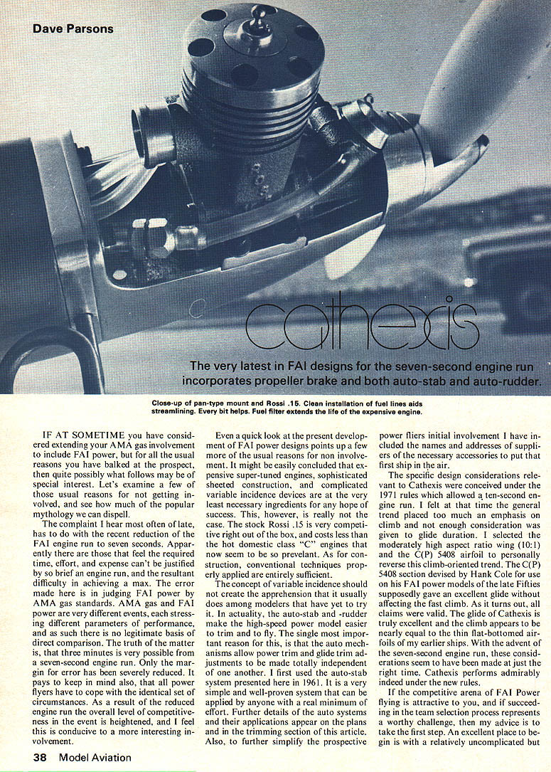
The very latest in FAI designs for the seven-second engine run incorporates propeller brake and both auto-stab and auto-rudder.
IF AT SOMETIME you have considered extending your AMA gas involvement to include FAI power, but for all the usual reasons you have balked at the prospect, then quite possibly what follows may be of special interest. Let's examine a few of those usual reasons for not getting involved, and see how much of the popular mythology we can dispel.
The complaint I hear most often of late has to do with the recent reduction of the FAI engine run to seven seconds. Apparently there are those that feel the required time, effort, and expense can't be justified by so brief an engine run, and the resultant difficulty in achieving a max. The error made here is in judging FAI power by AMA gas standards. AMA gas and FAI power are very different events, each stressing different parameters of performance, and as such there is no legitimate basis for direct comparison. The truth of the matter is, that three minutes is very possible from a seven-second engine run. Only the margin for error has been severely reduced. It pays to keep in mind also, that all power fliers have to cope with the identical set of circumstances. As a result of the reduced engine run the overall level of competitiveness in the event is heightened, and I feel this is conducive to a more interesting involvement.
Even a quick look at the present development of FAI power designs points up a few more of the usual reasons for non-involvement. It might be easily concluded that expensive super-tuned engines, sophisticated sheeted construction, and complicated variable incidence devices are at the very least necessary ingredients for any hope of success. This, however, is really not the case. The stock Rossi .15 is very competitive right out of the box, and costs less than the hot domestic class "C" engines that now seem to be so prevalent. As for construction, conventional techniques properly applied are entirely sufficient.
The concept of variable incidence should not create the apprehension that it usually does among modelers that have yet to try it. In actuality, the auto-stab and auto-rudder make the high-speed power model easier to trim and to fly. The single most important reason for this, is that the auto mechanisms allow power trim and glide trim adjustments to be made totally independent of one another. I first used the auto-stab system presented here in 1961. It is a very simple and well-proven system that can be applied by anyone with a real minimum of effort. Further details of the auto systems and their applications appear on the plans and in the trimming section of this article.
Also, to further simplify the prospective power flier's initial involvement I have included the names and addresses of suppliers of the necessary accessories to put that first ship in the air.
The specific design considerations relevant to Cathexis were conceived under the 1971 rules which allowed a ten-second engine run. I felt at that time the general trend placed too much an emphasis on climb and not enough consideration was given to glide duration. I selected the moderately high aspect ratio wing (10:1) and the C(P) 5408 airfoil to personally reverse this climb-oriented trend. The C(P) 5408 section devised by Hank Cole for use on his FAI power models of the late Fifties supposedly gave an excellent glide without affecting the fast climb. As it turns out, all claims were valid. The glide of Cathexis is truly excellent and the climb appears to be nearly equal to the thin flat-bottomed airfoils of my earlier ships. With the advent of the seven-second engine run, these considerations seem to have been made just about the right time. Cathexis performs admirably indeed under the new rules.
If the competitive arena of FAI Power flying is attractive to you, and if succeeding in the team selection process represents a worthy challenge, then my advice is to take the first step. An excellent place to begin is with a relatively uncomplicated but competitive design. Cathexis meets these criteria well, with the added advantage of being very forgiving and easily trimmed by the novice power flier.
Construction Notes
The model construction is relatively conventional and straightforward. The full-size plans are very well detailed and should pose no problems. A few general comments are warranted, however.
Wood selection is important, as it is entirely possible to end up an ounce or so overweight by using poor quality rather dense balsa. Use your own best judgment and try to balance strength and lightness throughout the model.
The first two versions of Cathexis were covered with Monokote, and this proved unsatisfactory for a number of reasons. My present models are double-covered with Japanese tissue and the combination of strength and surface rigidity would be difficult to improve upon. As a rule, I build the surfaces first. I like to think of building the fuselage around the surfaces, and it helps to have finished surfaces to facilitate this end. Also, it is a good idea to cure the covered surfaces for a couple of weeks before flying. Just letting the completed wing and stab set for a period of time seems to eliminate much of the creeping and warping characteristic of freshly finished surfaces when introduced to the hot sun at the flying field.
Stabilizer: Because of the shimmed TE to create the .050 droop, the ribs necessarily won't sit flat on the building board. For this reason the bottom main spar is not added until the basic framework is lifted from the board. Turn the stab upside down and add the 1/16 webbing in all rib bays, then glue in the bottom spar. Finally, turn the stab right side up and add the diagonal ribs and the tips. The finished stabilizer should weigh about one ounce.
Wing: The wing requires some attention to detail because of the undercambered section and the tapered wing tip planform. Be careful that the LE and TE are shimmed properly when pinned down to the building board. Also, at this point place the 1/8" sheet shim under the LE of both the right main panel and the right tip panel at the tip dihedral joint. This creates the necessary wash-in in the right main panel and allows the tip panel to be built back to flat at the very tip when joined to the main panel. The left wing panels are built flat. The spars, spar webbing, and diagonal ribs are added in the same order as outlined for the stabilizer.
The tip panel full and diagonal ribs are cut using the main panel rib templates. Tip rib blanks are cut to length and fit into their respective locations. Next, the ribs are marked for their new height at the LE and TE at each rib station. The rib height necessarily diminishes outward towards the tip. After marking and removing the tips, use the main panel rib template to cut the new upper and lower cambers. This is accomplished by aligning the LE of the template with the mark on the rib and simply rotating the template down over the rib blank until the template lines up with the mark at the TE of the rib blank. Follow the same procedure for the undercamber and the diagonal tip ribs. Now locate the spar positions on each tip rib, cut the spar notches and assemble.
After the wing panels are assembled and the glue thoroughly dry, shape the upper curve of the LE. Add the LE sheeting lapping it over the LE. When the sheeting is dry, trim away the excess and finish shaping the LE.
Double cover the wing with whatever technique suits you, and after doping set aside to cure. After curing for a few days, check each wing panel for proper warps. Correct any unintentional warps using steam. It's best to over-correct a little as invariably the surface will creep back slightly. In the mean time begin construction of the fuselage.
Fuselage: The fuselage is built on its side and a good straight building board is a definite prerequisite. What actually determines the height of the fuselage at the firewall is the dimension of whatever engine pan you choose. The balsa cheeks can be shaped to facilitate either the round or square type pans.
A technique I find useful is to build the fuselage nose about one inch longer than the plans show. The very last steps of construction will involve installation of the tank and firewall. This method allows you to strap everything together and check the CG location. Depending on the weight of the particular front-end hardware that you choose to utilize, the nose length may be somewhat shorter or longer than indicated on the plans.
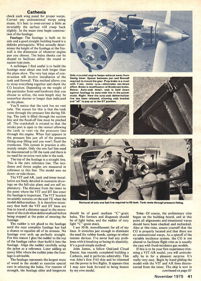
You'll notice that the tank has no vent tube. The reason for this is that the tank vents through the pressure line during filling. The tank is filled through the suction line and the flood-off line must be pinched off. The crankshaft is rotated so that the intake port is open to the venturi allowing the tank to vent via the pressure line through the engine. When fuel appears in the pressure line just aft of the pressure fitting stop filling and you won't flood the crankcase. This system in practice is ultimately simple. Only the one fuel line need be disconnected to fill the tank and there is no need for an extra vent tube in the tank.
The top of the fuselage is a straight line. This is the zero reference line. The incidence and thrust angles are measured in reference to this line. The model uses no down- or side-thrust.
The VIT and AR, tank and timer installation are finely detailed in isometric drawings on the full-size plans and are self explanatory. The distance from the timer to the point where the VIT and DT lines enter the fuselage is important. The VIT bracket invariably remains on the stab to TE when the model dethermalizes. It is therefore necessary that both the VIT and DT lines are free to travel a distance equal to the movement of the stab when dethermalized before being stopped at the point of entering the fuselage.
The rudder is not glued to the fuselage until the near complete fuselage has had a chance to equalize all of its stresses. No fuselage ever ends up perfectly straight. For this reason I glue the rudder to the top of the fuselage rather than build it into the fuselage. Align the rudder carefully using the pylon as a reference. Later adding an epoxy fillet where the rudder joins the fuselage is advisable.
The fuselage represents the largest mass of wood in the model so exercise special care in selecting the balsa. For reasons of strength, the fuselage sides and longerons should be of good medium "C"-grain balsa. The formers and diagonals should be of light balsa, and the rudder of very light "C"-grain stock.
I use 3-lb. monofilament for all of my lines. It stretches just enough to eliminate the need for rubber bands, springs or other tension devices. I've never had any problems with it breaking or losing its elasticity. It's a good simple method.
John James, a fellow Oakland Cloud Duster, has recently completed building a Cathexis, and it performs admirably. This was John's first FAI ship and he trimmed out the power in five flights. It appears that I may now look forward to being beaten by my own model.
Trim: Of course, the preliminary trim began on the building board, and at this point all alignments and intentional warps should have been checked and rechecked. Also at this time, assure yourself that the CG is properly located and that there are no unintentional warps. As a spin-off of the variable incidence system, the CG is not altered to facilitate flight trim as is usually the case with fixed-incidence gas models.
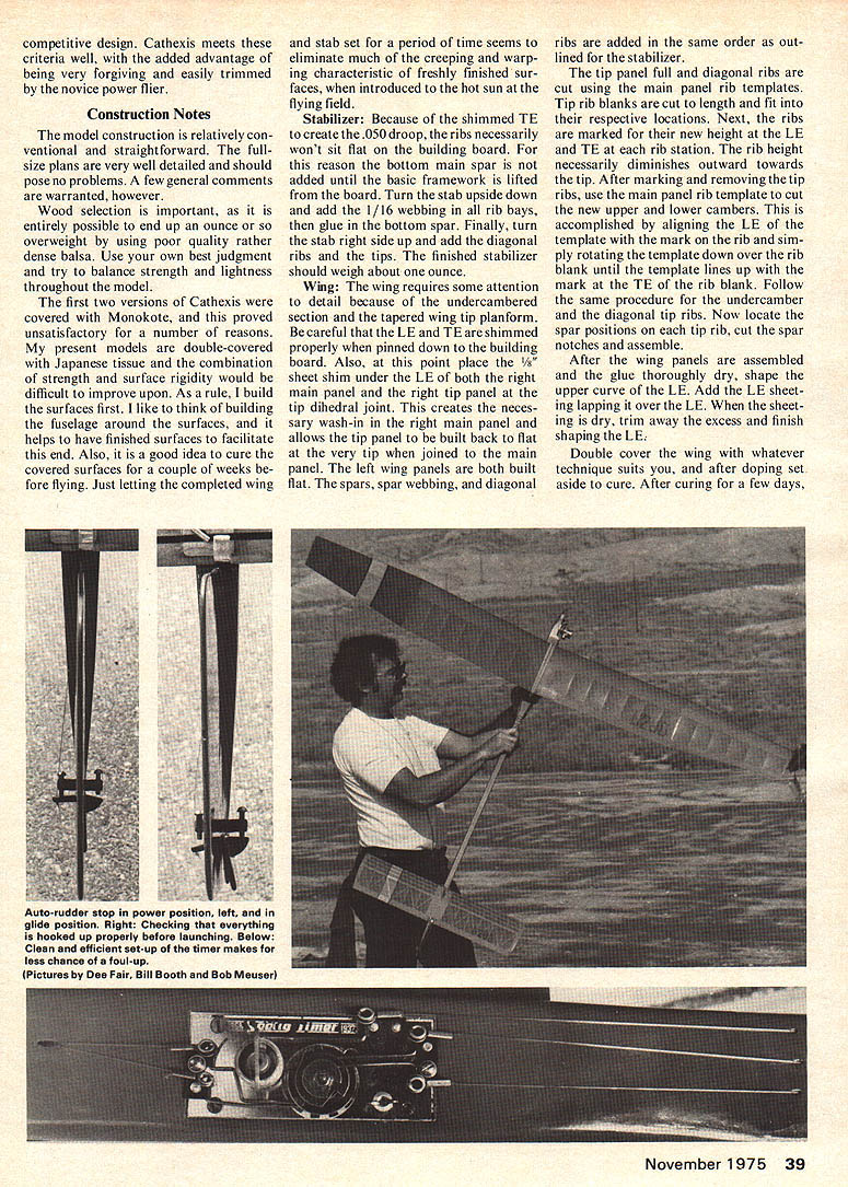
If this is to be your first experience trimming a VIT-AR model, you will undoubtedly be in for a pleasant surprise. It's really very easy. Begin by hand gliding the model with the VIT and AR lines disconnected from the timer. The ship is now in its glide mode. The stab should be up against its glide trim stop and the TE should be from 1/8" to 3/16" up off the fuselage. The auto-rudder should be deflected to the right 10-15 degrees. At this stage of the game, all that is required is a flat glide with a gentle right turn. Tweak the rudder and stab stop as necessary to achieve a satisfactory hand glide.
Before you light off that Rossi and get involved in serious trimming, let me briefly outline my particular utilization of the VIT and AR. The auto-rudder is more than just a transition device; it also determines the glide circle, as the model has no built-in stab tilt. This allows for a rather large deflection of the auto-rudder from the power setting to the glide setting, and as a result, the rudder tab is very effective at the end of the power run. So effective, in fact, that I have never found it necessary to deploy the auto-rudder before the flood-off is initiated. The usual timer sequencing might go something like: flood-off, two-second delay; rudder, two-second delay; auto-stab. Of course this delay sequence varies from model to model, but the order of deployment doesn't vary. After the power pattern has been trimmed, the auto-stab and rudder delays can be played with to achieve that perfect transition, without in any way affecting either the power or glide trim adjustments, a rather important plus in favor of the "gimmicks," I'd say.
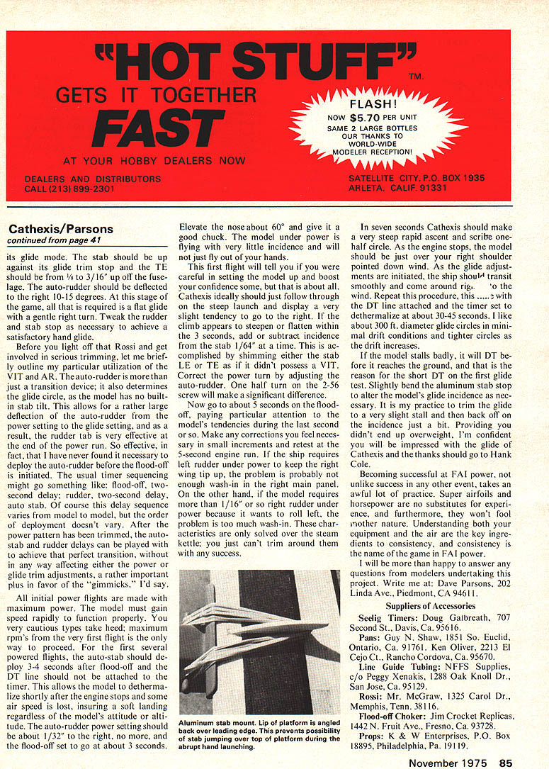
All initial power flights are made with maximum power. The model must gain speed rapidly to function properly. You overly cautious types take heed; maximum rpm's from the very first flight is the only way to proceed. For the first several powered flights, the auto-stab should deploy 3-4 seconds after flood-off and the DT line should not be attached to the timer. This allows the model to dethermalize shortly after the engine stops and some air speed is lost, insuring a soft landing regardless of the model's attitude or altitude. The auto-rudder power setting during the boost is about 1/2° to the right, no more, and the flood-off, set to go at about 3 seconds, ...
Elevate the nose about 60° and give it a good chuck. The model under power is flying with very little incidence and will not just fly out of your hands.
This first flight will tell you if you were careful in setting the model up and boost your confidence some, but that is about all. Cathexis ideally should just follow through on the steep launch and display a very slight tendency to go to the right. If the climb appears to steepen or flatten within the 3 seconds, add or subtract incidence from the stab 1/64" at a time. This is accomplished by shimming either the stab LE or TE as if it didn't possess a VIT. Correct the power turn by adjusting the auto-rudder. One half turn on the 2-56 screw will make a significant difference.
Now go to about 5 seconds on the flood-off, paying particular attention to the model's tendencies during the last second or so. Make any corrections you feel necessary in small increments and retest at the 5-second engine run. If the ship requires left rudder under power to keep the right wing up, the problem is probably not engine wash-in in the right main panel. On the other hand, if the model requires more than 1/16" or so right rudder under power because it wants to roll left, the problem is too much wash-in. These characteristics are only solved over the steam kettle; you just can't trim around them with any success.
In seven seconds Cathexis should make a very steep rapid ascent and describe one-half circle. As the engine stops, the model should be just over your right shoulder pointed downwind. As the glide adjustments are initiated, the ship should transit smoothly and come around right into the wind. Repeat this procedure, this time with the DT line attached and the timer set to determine a time of about 30-45 seconds. I like about 30 ft. diameter glide circles in minimal drift conditions and tighter circles as the drift increases.
If the model stalls badly, it will DT before it reaches the ground, and that is the reason for the short DT on the first glide test. Slightly bend the aluminum stab stop to alter the model's glide incidence as necessary. It is my practice to trim the glide to a very slight stall and then back off on the incidence just a bit. Providing you didn't end up overweight, I'm confident you will be impressed with the glide of Cathexis and the thanks should go to Hank Cole.
Becoming successful at FAI power, not unlike success in any other event, takes an awful lot of practice. Super airfoils and horsepower are no substitutes for experience, and furthermore, they won't fool mother nature. Understanding both your equipment and the air are the key ingredients to consistency and consistency is the name of the game at FAI power.
I will be more than happy to answer any questions from modelers undertaking this project. Write me at: Dave Parsons, 202 Linda Ave., Piedmont, CA 94611.
Suppliers of Accessories
- Seelig Timers: Doug Galbreath, 707 Second St., Davis, CA 95616.
- Pans: Guy N. Shaw, 1851 So. Euclid, Ontario, CA 91761.
- Ken Olver, 2213 El Cejo Ct., Rancho Cordova, CA 95670.
- Line Guide Tubing: NFFS Supplies, c/o Peggy Xenakis, 1288 Oak Knoll Dr., San Jose, CA 95129.
- Rossi: Mr. McGraw, 1325 Carol Dr., Memphis, Tenn. 38116.
- Flood-off Choker: Jim Crockett Replicas, 1442 N. Fruit Ave., Fresno, CA 93728.
- Props: K & W Enterprises, P.O. Box 18895, Philadelphia, Pa. 19119.
Transcribed from original scans by AI. Minor OCR errors may remain.

