
Caudimordax
Iskandar Taib
Design philosophy
American Combat design has traditionally favored speed over turning ability — heavy, high-power engines (Hoffelts, custom Foxes) bolted to large, 300–400 sq. in. airframes are common. Those engines typically weigh about 9½ oz.
Caudimordax takes the opposite approach: prioritize a high rate of turn and a small turning radius by using a light engine and a high-aspect-ratio wing. The trade-off is top speed: a Caudimordax with a Brat .28 will fly about 10–15 mph slower in level flight than a typical Fast Combat ship, but its much tighter turns cost less speed than heavier ships do.
Advantages of smaller engines
- Three ounces of fuel can last up to five minutes.
- The airplane is less likely to dislocate your shoulder on launches.
- A slower, tight-turning airplane is harder for an opponent to line up on; overshoots often create kill opportunities.
- Smaller engines cost far less than larger ones.
Use in Outlaw/FAI contests
Caudimordax adapts well to the Outlaw FAI (Fast/Slow) contests growing in the Midwest. Typical rules: .15 engines, 52 ft lines, and no restrictions on engine tank setups or nitro content.
- Most Schnuerle-ported, double-ball-bearing .15s weigh about 6 oz — roughly 3½ oz less than a Brat .28.
- To use a smaller engine, alter bearer spacing and mount position so the engine sits slightly further forward (bearer spacing is typically reduced by about 1/8 in.).
- Minor modifications to the Brat .28 center block and mounts are needed when swapping engines.
Wing design and induced drag
Much of Caudimordax’s agility is due to its high-aspect-ratio wing and relatively thick airfoil.
- Parasitic drag is due to friction and form drag (proportional to surface area and protuberances); streamlining reduces it.
- Induced drag arises from the wing producing lift: pressure differences cause spanwise flow and tip vortices, which require energy and thus manifest as drag. Induced drag increases with lift and decreases with aspect ratio.
- A high-aspect-ratio wing produces less induced drag for a given lift. A thicker airfoil delays high-speed stall and adds lateral stability, helping control snap rolls common to high-aspect-ratio designs.
Reducing tip vortices — strategies
- Tip fences: impede spanwise flow around the tip (beneficial on low-aspect-ratio wings).
- Hoerner anti-vortex tips: shaped to force airflow opposite tip-vortex direction; effective only under positive Gs and can worsen the problem inverted.
- Forward sweep: encourages flow toward the root, but requires very rigid wings to resist aeroelastic divergence.
- Planform optimization: Schuemann (or equivalent tapered) planforms and elliptical planforms minimize induced drag. A non-tapered wing is only ~60–65% as efficient as an elliptical wing of the same aspect ratio; a tip chord equal to 60–65% of the root chord gives ~90–95% of elliptical efficiency.
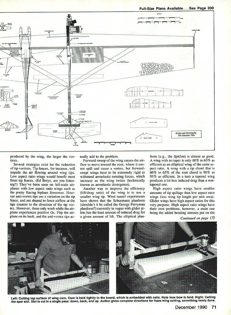
Aspect ratio and Caudimordax wing specifics
- Chosen aspect ratio: 6:1.
- Wingspan: 48 inches (convenient for cutting from 2-ft foam sheets).
- Mean chord: 8 in. Root chord 10 in.; tip chord 6 in. (60% tip/root).
- Trailing edge swept forward 3 in.; leading edge swept back 1 in.; net quarter-chord sweep ≈ 0.
- A swept leading edge reduces snap-roll tendency seen with a straight leading edge and eases spar placement and lead-out sweep.
High-aspect-ratio wings reduce tip spillage but increase bending stresses at the root; the chosen AR balances efficiency and structure weight.
Eliminating high-speed stall
- Tight turns demand more lift, which increases angle of attack. Beyond a critical angle the airflow separates and the wing stalls, causing sudden drag increase and possible wing-drop.
- Two approaches:
- Limit control deflections to avoid excessive turn tightness.
- Use a thicker, blunter airfoil that stalls at higher Gs (trades off some top speed for safer, more predictable turns).
- Caudimordax uses a thick root section (~15%) and an even thicker tip (~25%) so the root stalls before the tip, reducing tip-drop and lateral instability.
Longitudinal stability
Stability is essential for predictable, tight turning.
- The stabilator (or horizontal stabilizer) provides stability by opposing the wing's nose-down pitching moment. Larger stabilizers increase the stability margin; a longer tail moment also improves stability by increasing the moment arm.
- Historical note: early Spitfires had small stabilizers and narrow CG limits; adding aft tanks and heavier engines later required larger tail surfaces to restore stability.
- Caudimordax uses a 12 x 3 in. stabilator; earlier versions with a 9 x 3 in. tail were less predictable. Proper tail area and moment arm keep turns from tightening uncontrollably.
Construction
Cutting parts
- Cut center rib, tip ribs, stabilator, lead-out guide, bellcrank plate, control horn, and engine mount assembly on a scroll saw or band saw for accuracy.
- Final shaping: belt or disc sander. Set tools to cut/sand at perfect 90°.
- Recommendation: a good band saw is preferable to many scroll saws (more power, smoother cuts, useful for resawing balsa, cutting aluminum sheet, etc.).
Engine mount assembly
- Glue engine mount assembly with a thick cyanoacrylate (CyA) like Special-T.
- Use a vertical grain balsa spacer and 1/4-in. ply side plates. Reinforce with two dowels through the maple center rib. Trial-fit and drill holes individually for each engine/center block.
- Compensate loose fits with 1/64-in. ply spacers where needed.
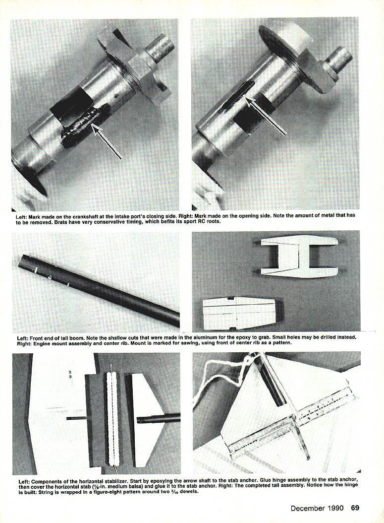
Arrow-shaft tail boom
- Typical shaft: 1/4-in. O.D., ~.019-in. wall (arrow shaft type, often marked “2117”). Graphite shafts also work if available.
- Drill the hole in the rear of the center rib with a drill press or appropriate jig (a crooked tail is noticeable). Use 1/64-in. increment drill bits for exact fit.
- Cut the rear notch on the boom with a band saw. Drill two or three shallow holes or make shallow notches in the front end for an epoxy anchor before gluing boom to block. Stuff tissue into the boom front to keep epoxy out; use slow-curing epoxy. Ensure the rear notch is horizontal.
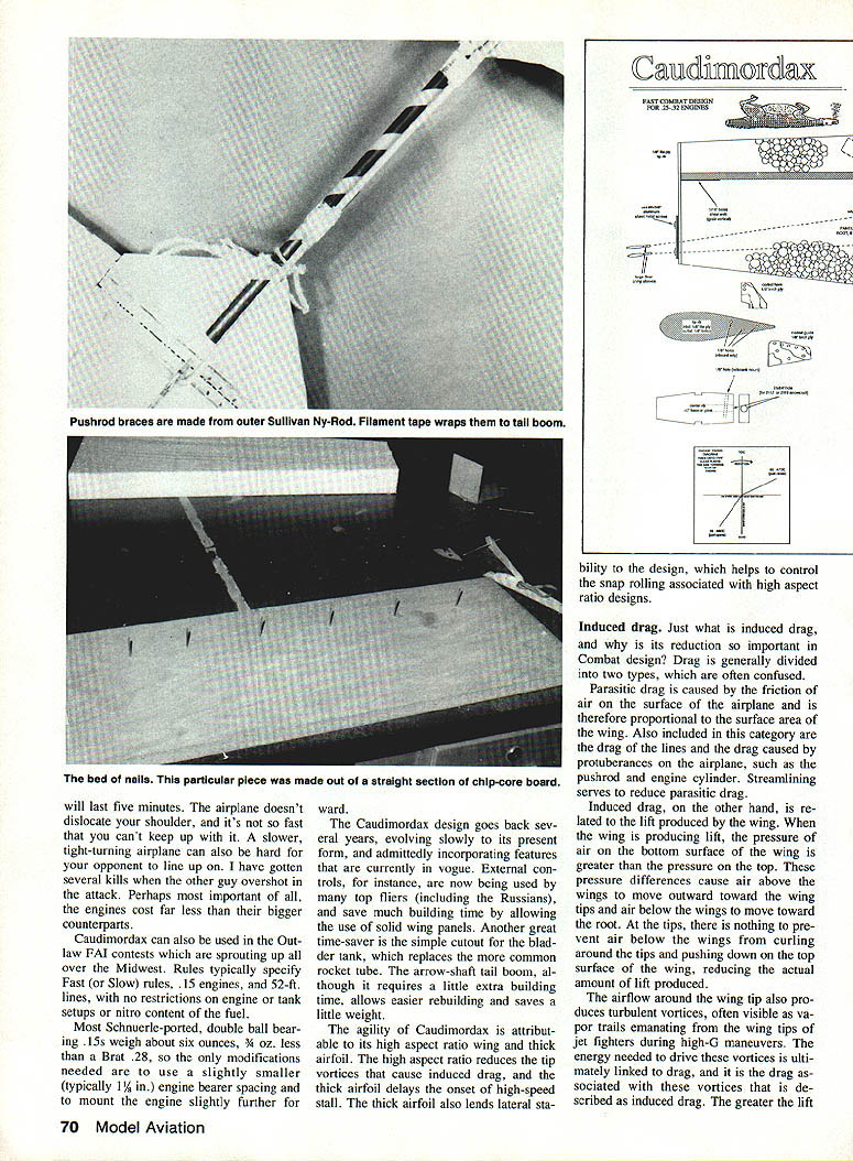
Cutting foam cores
This method (credited to Doc Passan) is efficient and repeatable.
- Cutting bow: use 1 x 2-in. furring strip. Cutting wire: 0.015-in. braided control line. Power source: 12–13 V at 3–4 A (Variac, car battery, or a dimmer switch in series with a 200 W bulb as used by Phil Carter).
- Templates: 1/8-in. Formica, edges sanded smooth and waxed with candle wax for clean cuts. Paste Xeroxed patterns onto Formica. Note: template centerline is 1/8 in. from the bottom to compensate for foam thickness variations and kerf loss.
- Cutting surface: flat plywood or particle board with nails driven through to hold foam (nails should penetrate ≈1 in.).
- Jig for blanks: two vertical templates spaced about 27 in. apart at a table edge; allow space for 8-ft foam sheets behind. For mass production, make 2-ft-high jigs to cut many blanks at once.
- Hold foam layers with bamboo skewers. Use double-pointed pins (1/8-in. aluminum or brass welding rod) driven from the bottom so they don't interfere with the wire. Start the wire in the middle of the blank, cut toward the nose, then return and cut toward the tail. Re-pin if the blank moves.
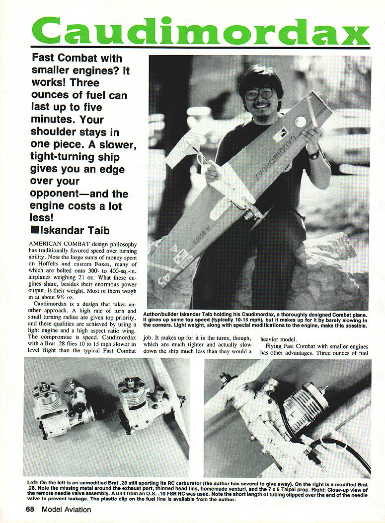
Engine modifications (Brat .28 and Combat tuning)
The Brat .28 is a light engine with conservative induction timing (designed for RC sport). Combat use benefits from:
- Retiming the induction port: grind a small amount of metal from the crankcase on the side marked "opening" and add a small amount of metal (solder) on the side marked "closing" to advance timing slightly. Changes are small — Brats start with conservative timing.
- Replace the RC carburetor with a large-diameter intake stack (sometimes called an intake trumpet or venturi) for better induction in Combat.
- Remove excess weight and nonessential parts. Head fins contribute little to cooling and can be ground down (leave ~3/32 in.). Before grinding: remove the glow plug and plug ports (air intake and exhaust) with paper toweling; after grinding, wash filings out thoroughly with detergent and water.
- To remove muffler lugs or other external lugs, disassemble carefully, stuff the case with toweling before grinding, and protect ports; clean filings out before reassembly. Avoid removing bearings.
Tactics, name, and development
- Tactically, follow your opponent through turns — Caudimordax’s superior turning radius can negate level-speed disadvantages. Look for leading-edge kills when opponents overshoot during streamer attacks.
- The name Caudimordax (nicknamed "Quasimodo" by Doc Passan) comes from Tolkien's Farmer Giles of Ham. Historically Combat designs have borrowed Tolkien names (Orcs, Anduril, Glamdring, etc.). Caudimordax (Tail-biter) is apt for a Combat ship that seeks to snap at opponents’ tails.
Further development is expected: try alternate airfoils, tail moments, construction techniques, or even larger engines (with appropriate strengthening of the center block and mounts). Nearly all Caudimordax construction techniques were influenced by other builders; acknowledgments go to Terry "Doc" Passan (foam cutting, engine-mounting, tail hinge, bellcrank and pushrod ideas), Phil Carter (arrow-shaft tail-boom, bladder tank, use of smaller engines), and Richard Wilson (front spar and foam-cutting bow).
Transcribed from original scans by AI. Minor OCR errors may remain.

