
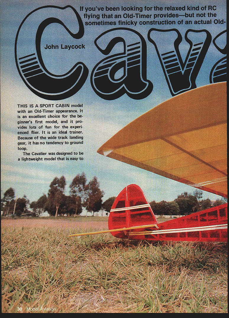

If you've been looking for the relaxed kind of RC flying that an Old-Timer provides—but not the sometimes finicky construction of an actual Old-Timer, the Cavalier is for you.
Cavalier
John Laycock
This is a sport cabin model with an Old-Timer appearance. It is an excellent choice for the beginner's first model, and it provides lots of fun for the experienced flier. It is an ideal trainer. Because of the wide-track landing gear, it has no tendency to ground loop.
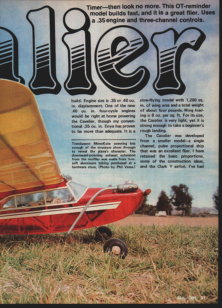
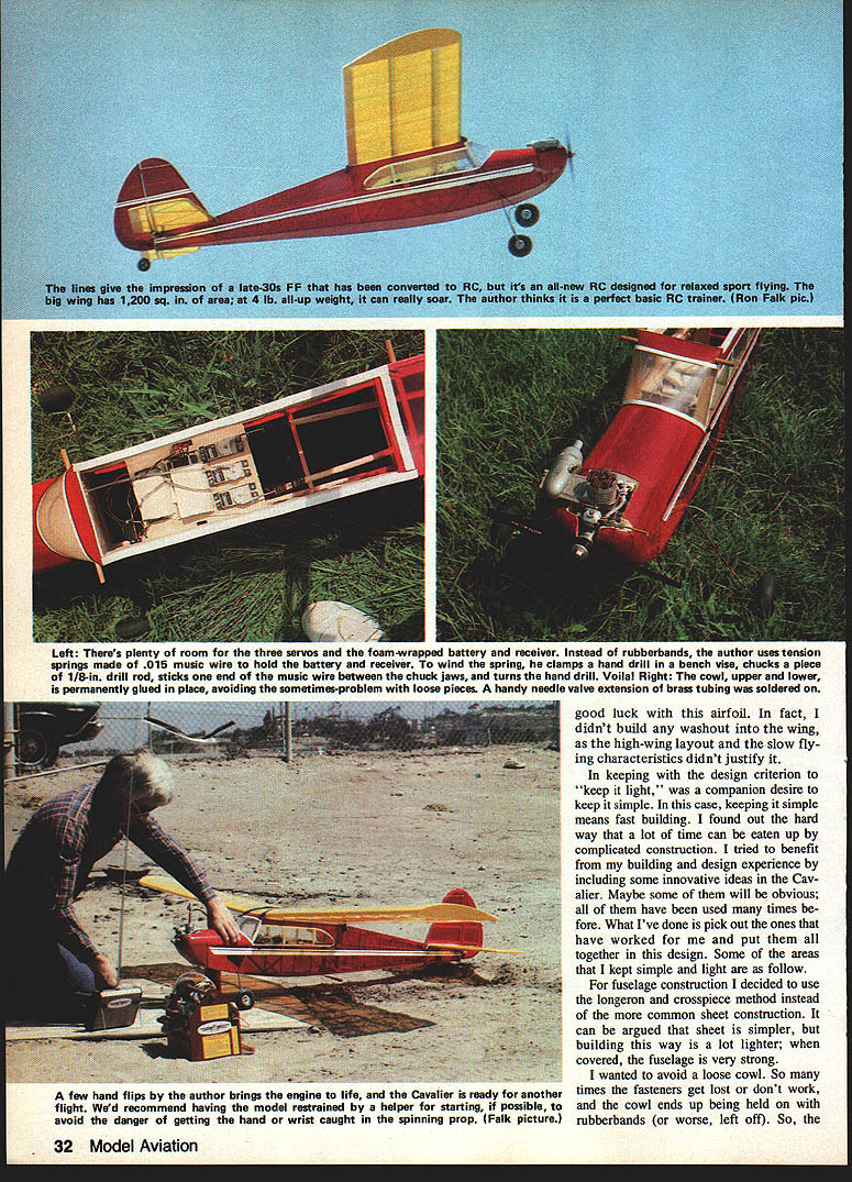
The Cavalier was designed to be a lightweight model that is easy to build. Engine size is .35 or .40 cu. in. displacement. One of the new .40 cu. in. four-cycle engines would be right at home powering the Cavalier, though my conventional .35 cu. in. Enya has proven more than adequate. It is a slow-flying model with 1,200 sq. in. of wing area and a total weight of about four pounds. Wing loading is about 8 oz. per sq. ft. For its size, the Cavalier is very light, yet it is strong enough to take a beginner's rough landing.
The Cavalier was developed from a smaller model—a single-channel, pulse-proportional ship that was an excellent flier. I have retained the basic proportions, some construction ideas, and the Clark Y airfoil. I've had good luck with this airfoil. In fact, I didn't build any washout into the wing, as the high-wing layout and the slow-flying characteristics didn't justify it.
In keeping with the design criterion to "keep it light," a companion desire was to keep it simple. In this case, keeping it simple means fast building. I found out the hard way that a lot of time can be eaten up by complicated construction. I tried to benefit from my building and design experience by including some innovative ideas in the Cavalier. Maybe some of them will be obvious; all of them have been used many times before. What I've done is pick out the ones that have worked for me and put them together in this design. Some of the areas that I kept simple and light are as follows.
For fuselage construction I decided to use the longeron-and-crosspiece method instead of the more common sheet construction. It can be argued that sheet is simpler, but building this way is a lot lighter; when covered, the fuselage is very strong.
I wanted to avoid a loose cowl. So many times the fasteners get lost or don't work, and the cowl ends up being held on with rubber bands (or worse, left off). So, the cowl upper and lower are permanently glued in place, avoiding the sometimes-problem of loose pieces. A handy needle-valve extension of brass tubing was soldered on. A few hand flips to break in the engine and the Cavalier was ready for another flight. We recommend having the model restrained and a helper start the engine, if possible, to avoid the danger of getting a hand or wrist caught in the spinning prop.
There's plenty of room for three servos, a foam-wrapped battery pack and receiver. Instead of rubber bands, I use tension springs made of .015 music wire to hold the battery and receiver. Wind the spring around a clamp — a hand drill or bench vise works well. Chuck a piece of 1/8-in. drill rod, stick the end of the music wire between the chuck jaws and turn the hand drill — voila!
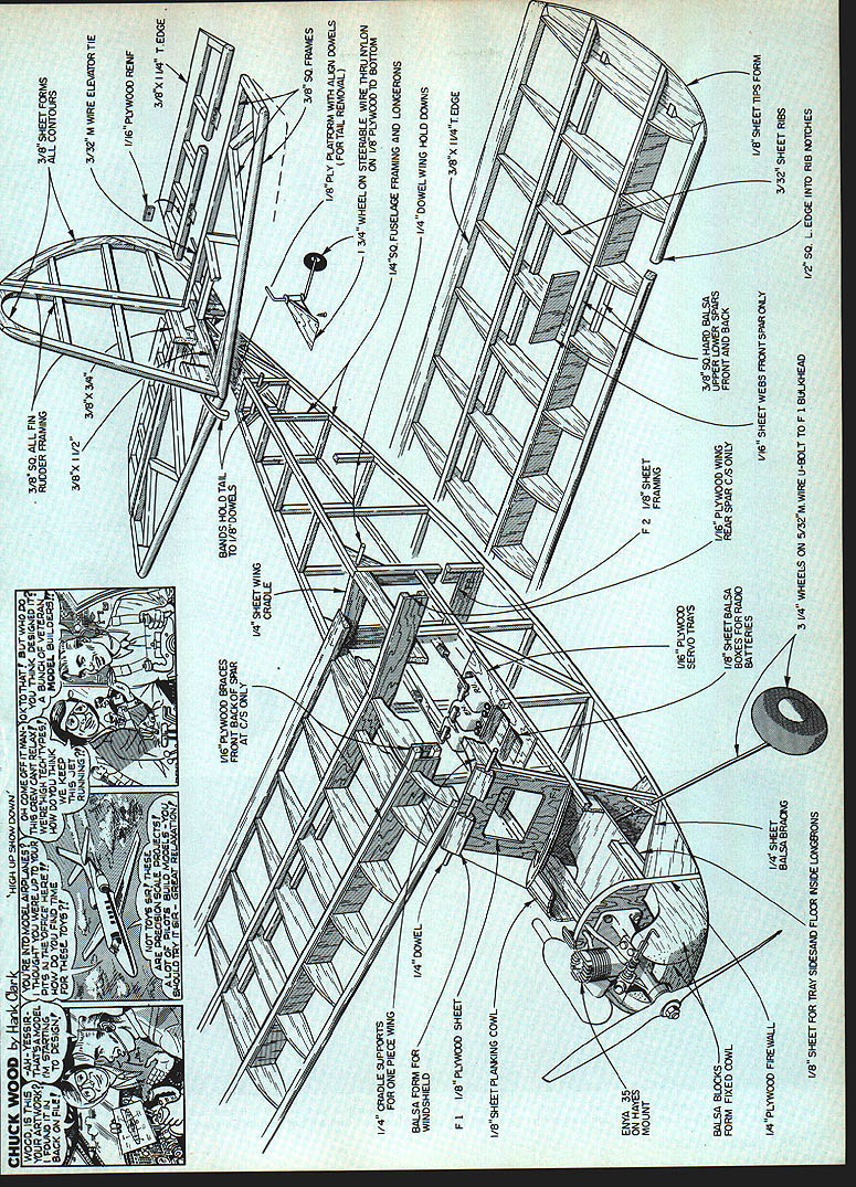
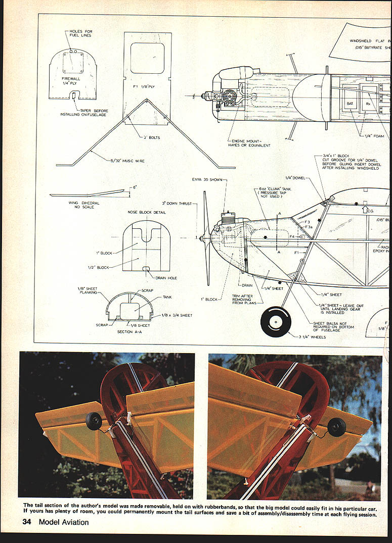
Nose block and construction notes
- Holes for fuel lines
- Firewall: 1/4" plywood
- Taper before installing on fuselage
- F1: 1/8" plywood
- 5/32" music wire
- 3° down thrust
- Engine mount — Hayes or equivalent (Enya .35 shown)
- Windshield: flat — 0.015" butyrate sheet
- Battery / Receiver layout: BAT, Rx
- 1/4" foam
- 3/4" x 1" block — cut groove for 1/4" dowel before gluing; insert dowel after installing windshield
- 1/4" dowel
- 6 oz. "clunk" tank (pressure tap not used)
- Nose block detail: 1" block, 1/2" block, drain hole
- Wing dihedral — no scale
- 1/8" sheet planking
- Scrap tank / 1/8" x 3/4" sheet
- Section A-A: drain, 1/4" sheet (trim after removing from plans)
- 1/4" sheet — leave out until landing gear is installed
- Sheet balsa not required on bottom of fuselage
- 3 1/4" wheels
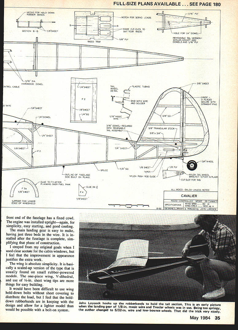
- Align dowels for tail removal on 1/8" plywood
- Bottom is 1/4" sq. fuselage framing and longerons
- 1/4" dowel wing hold dowels
- 1/8" plywood firewall
- 1/8" sheet for tray sides and fuselage side longerons
- 1/16" plywood servo trays
- 1/8" sheet balsa boxes for radio batteries — make cut-outs to suit your radio
- 1/8" plywood radio tray
- Hooks for hold-down rubber bands
- Section B-B
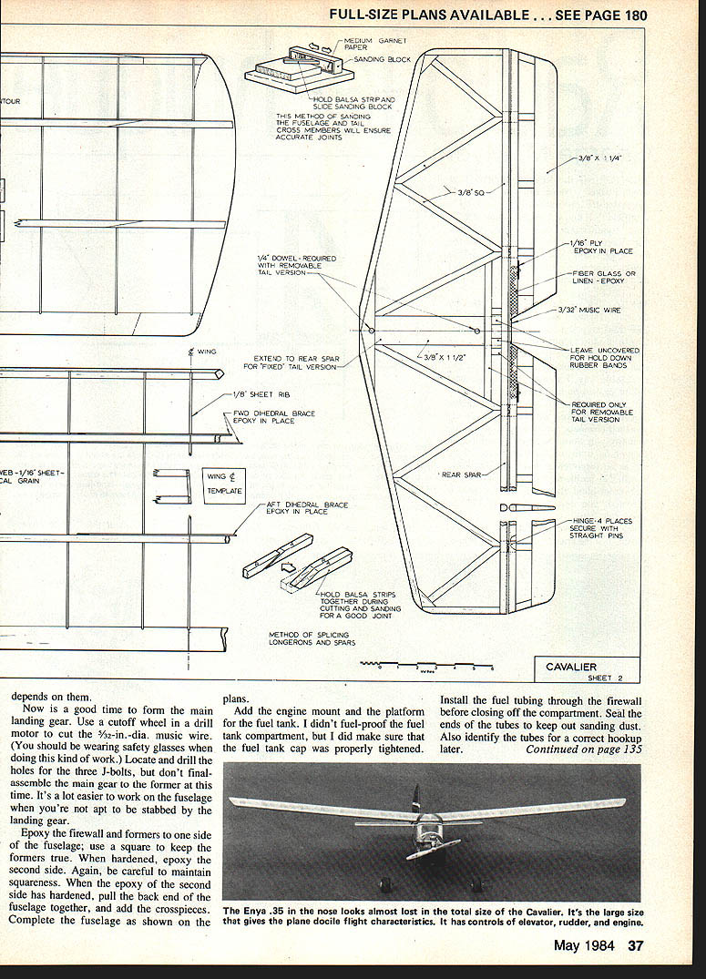
- Full-size plans available — see page 180
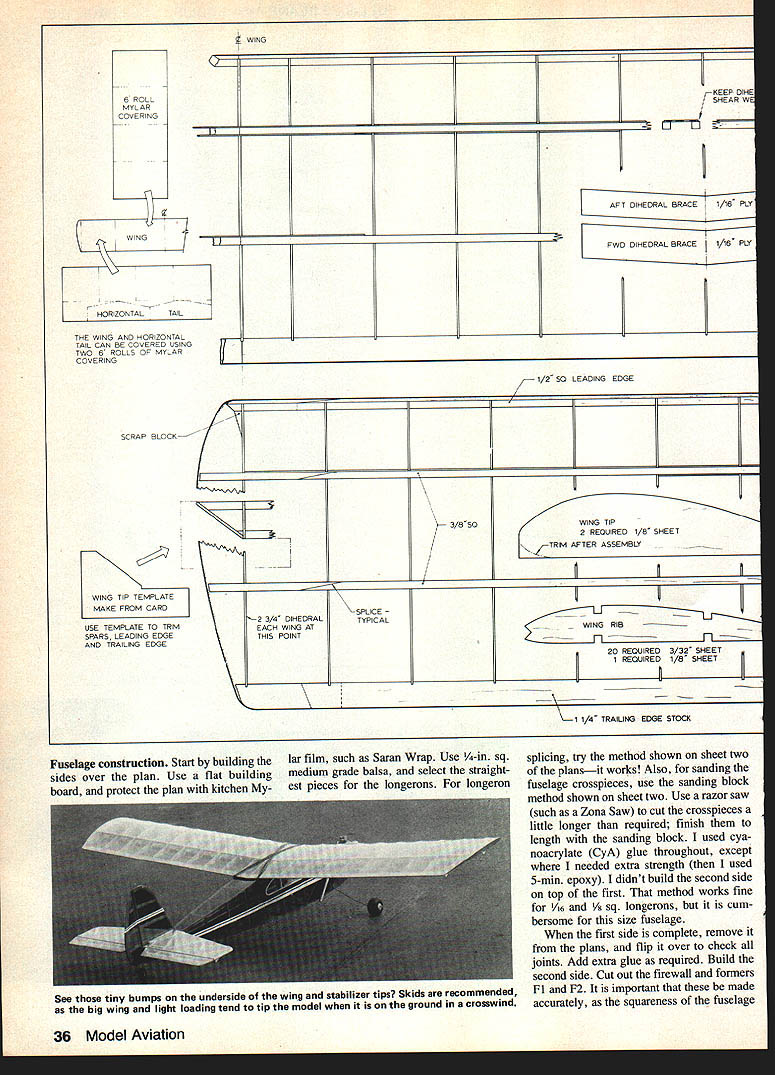
Fuselage construction
Start by building the sides over the plan. Use a flat building board, and protect the plan with kitchen Mylar film such as Saran Wrap. Use 1/4-in. sq. medium grade balsa, and select the straightest pieces for the longerons. For longeron splicing, try the method shown on sheet two of the plans — it works. Also, for sanding the fuselage crosspieces, use the sanding-block method shown on sheet two. Use a razor saw (such as a Zona Saw) to cut the crosspieces a little longer than required; finish them to length with the sanding block.
I used cyanoacrylate (CYA) glue throughout, except where I needed extra strength (then I used 5-min. epoxy). I didn’t build the second side on top of the first. That method works fine for 1/16 and 1/8 sq. longerons, but it is cumbersome for this size fuselage.
When the first side is complete, remove it from the plans, and flip it over to check all joints. Add extra glue as required. Build the second side. Cut out the firewall and formers F1 and F2. It is important that these be made accurately, as the squareness of the fuselage will depend on them. Install the firewall and F2 on one fuselage side only; leave the other side off until the landing gear is installed. Sandwich the 1/8-in. sheet balsa top and bottom sheeting between the sides when the fuselage is assembled. Join the halves and glue the formers into position. Add the top and bottom pieces, and check alignment by sighting along the longerons before the glue sets. Install the windshield and cowl blocks.
There’s plenty of room for three servos, a foam-wrapped battery and the receiver in the radio compartment. The tray method of radio installation has worked fine for me; use epoxy to mount the tray. Incidentally, the tray strengthens the center of the fuselage. If you are not sure about getting the center of gravity located correctly, install the radio tray last, and move it fore and aft to get the proper balance position.
To make the tension spring clamps for the battery and receiver, put a piece of 1/8-in. drill rod in a bench vise, stick the end of the .015 music wire between the chuck jaws of a hand drill and turn the hand drill — voila!
The cowl upper and lower are permanently glued in place to avoid the sometimes-problem of loose pieces. Use a Hayes mount or equivalent for the engine firewall. The landing gear is formed from 5/32" music wire and is held to the fuselage as shown on the plans; file the wire taper before installing on the F1 bulkhead.
Now is a good time to form the main landing gear. Use a cutoff wheel in a drill motor to cut the 5/32-in.-dia. music wire. Wear safety glasses when doing this kind of work. Locate and drill the holes for the three J-bolts, but don't final-assemble the main gear to the former at this time — it's a lot easier to work on the fuselage when you're not apt to be stabbed by the landing gear.
Epoxy the firewall and formers to one side of the fuselage; use a square to keep the formers true. When hardened, epoxy the second side. Again, be careful to maintain squareness. When the epoxy of the second side has hardened, pull the back end of the fuselage together, and add the crosspieces. Complete the fuselage as shown on the plans.
Add the engine mount and the platform for the fuel tank. I didn't fuel-proof the fuel tank compartment, but I did make sure that the fuel tank cap was properly tightened. Install the fuel tubing through the firewall before closing off the compartment. Seal the ends of the tubes to keep out sanding dust. Also identify the tubes for correct hookup later.
Epoxy the balsa blocks in place for the engine cowl. Shape and sand them to final contour. I keep a very sharp chisel handy for shaping and carving balsa; I find it is faster than using razor blades or a knife. Use the chisel to carve close to final size, and finish by sanding. Add the gussets. The windshield and side windows are affixed with contact cement. The engine compartment is given two coats of epoxy paint. It is a little tricky to paint around the engine mount; I used a long cotton swab inserted through the drain hole to get below the engine mount. It is better to have too much paint there than not enough.
If you are ready to cover the fuselage, now is the time to add the main landing gear. After covering, add the tail wheel assembly and the wing and tail hold-down dowels.
Cavalier — general construction features
- The front end of the fuselage has a fixed cowl. The engine is installed upright for simplicity, easy starting, and good cooling.
- The main landing gear is easy to make, having just three bends in the wire. It is installed after the fuselage is complete, simplifying that phase of construction.
- I strayed from my original goals when I used clear acetate for the cabin windows, but the improvement in appearance justifies the extra work.
- The wing is absolute simplicity: a one-piece wing, V-dihedral, and 1/8-in. sheet wing tips. It is basically a scaled-up version of the type usually found on small rubber-powered models.
- Wing hold-downs: I prefer hold-down rubber bands rather than wing bolts, since sheet covering to distribute bolt loads would add weight. Use rubberbands to keep the model light.
Wing
Once the ribs are cut, the wing panels assemble quite fast. Four ribs can be cut from one 3 x 36-in. sheet. I made a rib template from 1/16" ply, splicing two pieces together to make a big enough template.
Build each wing half flat on the plan. Before joining the two wing halves, complete the wing tips, as it is easier to finish with just half a wing.
There are a number of ways to join the wing halves. If you have a favorite, by all means use it. A method that works well for me is as follows: as I build each wing half, I trim the spar and the leading and trailing edges to the correct length and dihedral angle. The dihedral angle template is very useful and worth the effort necessary to make it. Build both wing halves, and add the 1/8-in. center rib to one wing half. Block up one half, bring the two halves together, and check the fit. When you are satisfied, glue with epoxy. Now you have a complete wing needing only the dihedral reinforcing. Carefully slot the center ribs for the dihedral braces. Glue them in with epoxy, and clamp in place. Finally, add the shear webs. The wing is then ready for final sanding.
Tail
Construction is straightforward. Square the ends of the crosspieces with the sanding block. Be careful when cutting the slots for the hinges. Unless the hinge pins are exactly in line, it will take extra force to move the control surface, putting extra load on the radio servo and battery.
Whether to make the tail assembly removable or epoxy it permanently to the fuselage usually depends on the space in your vehicle. With my mid-sized, two-door car, I can carry the wing inside the passenger area. The fuselage and removable tail are carried in the trunk. If your transportation permits a one-piece fuselage and tail, then build it that way — you'll save yourself some extra work.
Finishing
I used translucent Super MonoKote. It looks great on the built-up fuselage, and it also adds to the sense of being lightweight. The wing and tail can be covered with two rolls if the pieces are cut as shown on the plan. If you use this method, make the Super MonoKote lap joint over a wing rib, and don't shrink any part until the whole wing has been covered. Make sure the lap joint is well-sealed. I use a regular household iron for the final shrinking.
For trim around the windows, use 1/2-in. pressure-sensitive tape. After covering, add the tip skids to the wing and horizontal tail — don't fly without them! For holding the wing down, make six 10-in. loops (20 in. of rubber) from 1/4-in. rubber strip.
Flying
You will find the Cavalier to be an easy plane to fly. However, if you haven't flown multi-channel RC before, have a qualified flier help you during the early flights. The Cavalier doesn't have any vices. It's not likely to ground-loop on takeoff or landing.
Basic commonsense rules apply:
- On takeoff, make sure the model is heading directly into the wind. This is important on lightly-loaded models such as the Cavalier.
- Landings are fun. The final approach should be directly into the wind. Cut the engine to idle. Add up-elevator trim to establish the glide, and start the flare-out when the model is about six feet above the ground. Keep giving more up-elevator until touch-down. The stick should be all the way back at this point. As at takeoff, there is very little roll.
- In windy weather, don't attempt taxiing. Once the model is turned crosswind, the wind will tend to tip it over. This does very little structural damage—the wing is strong—but it can ruin an otherwise good landing. I usually kill the engine and carry the model back to the pits.
Have fun building and flying the Cavalier. It's not a model that is pushing the state of the art, but it is honest-to-goodness fun to fly.
Transcribed from original scans by AI. Minor OCR errors may remain.

