
Centrifugal Force
George Abbott
What are reasonable numbers for model-airplane purposes? Typical radio-control sport airplanes fly at 35 to 55 mph; pattern airplanes, 50 to 85 mph; and pylon racers, 125+ mph. Turn radius ranges from about 10 ft for a sharp pullout to 100 ft for a big loop, and 50 to 100 ft for a pylon turn. When estimating the size of maneuvers, remember that most paved RC runways are about 300 ft long and 30 ft wide, and most residential utility poles are 18 to 30 ft high.
Of the several forces that act on an aircraft in flight, centrifugal force is one of the most important. It will help us in both design and flight if we understand this force.
If an object is traveling along a curved path, it experiences a force directed outward from the center of the curve. A childhood example is tying a rock to a string and whirling it around your head. The force the rock experiences is called centrifugal force, and it is a very important factor in the behavior of airplanes.
Whenever an airplane changes direction, centrifugal force causes the apparent weight of the airplane to change. For example, during pullout from a dive the apparent weight of the airplane will increase, while if the airplane pushes over from level flight the apparent weight will decrease. A commonly used term for these forces is g force.
May the force be with you — centrifugal force, that is. It's an important factor in model design and flight.
A force of one g is equivalent to the acceleration caused by the earth's gravity, generally accepted as 32 ft./sec./sec. An object acted upon by gravity will exert a force equal to its mass multiplied by g; this force is called weight and is expressed in pounds (English system). This is Newton's second law:
F = M × a
Weight and mass are related by the acceleration of gravity:
W = M × g
- M = mass (slugs)
- W = weight in pounds
- a = acceleration, ft./sec./sec.
- g = acceleration of gravity, 32 ft./sec./sec.
From this it's clear that the mass of a body is its weight divided by g. Thus an object having a weight of 64 lb would have a mass of 2 slugs. If we express acceleration in terms of g, we always get forces in terms of weight, which avoids a lot of confusion.
Centrifugal force results from the acceleration caused by a moving object's change of direction acting upon the mass of that object. The formula for this acceleration is:
a = V^2 / r
- a = acceleration, ft./sec./sec.
- V = velocity, ft./sec.
- r = radius of curve, ft.
We can combine this with Newton's law and do a little arithmetic to get a formula that accepts speed in miles per hour and provides the result as acceleration in multiples of gravity (g):
g = (mph^2 × 0.0672) / r
- g = centrifugal acceleration, in multiples of gravity (i.e., multiples of weight)
- mph = speed in miles per hour
- r = radius of curve, ft.
(Notice that speed is squared in these formulae.)
The centrifugal force will always be directed outward from the center of the curving path. The total force acting on the object will be the vector sum (resultant) of these forces. In this paper we will use the following terminology:
- W = weight, lb
- g = centrifugal force, in multiples of W (i.e., multiples of gravity)
- G = total force, in multiples of W (G = g + 1, where the +1 accounts for gravity)
Thus, an object with W = 10 lb subjected to 3 g (total) would experience a total force G = 30 lb. For simplicity, we will often normalize to a weight W = 1 lb so everything comes out in terms of g.
Control-line airplanes are subject to centrifugal force in their circular flight; this is a primary factor in maintaining line tension. These models may also employ aerodynamic means such as outside rudder to ensure line tension at low speeds, when overhead, or when flying in wind. Speed models generally don't need this help.
Control-line models fly at speeds from 35 to 55 mph for sport and stunt models, around 100 mph for combat and carrier models, and well over 100 mph for many Speed models.
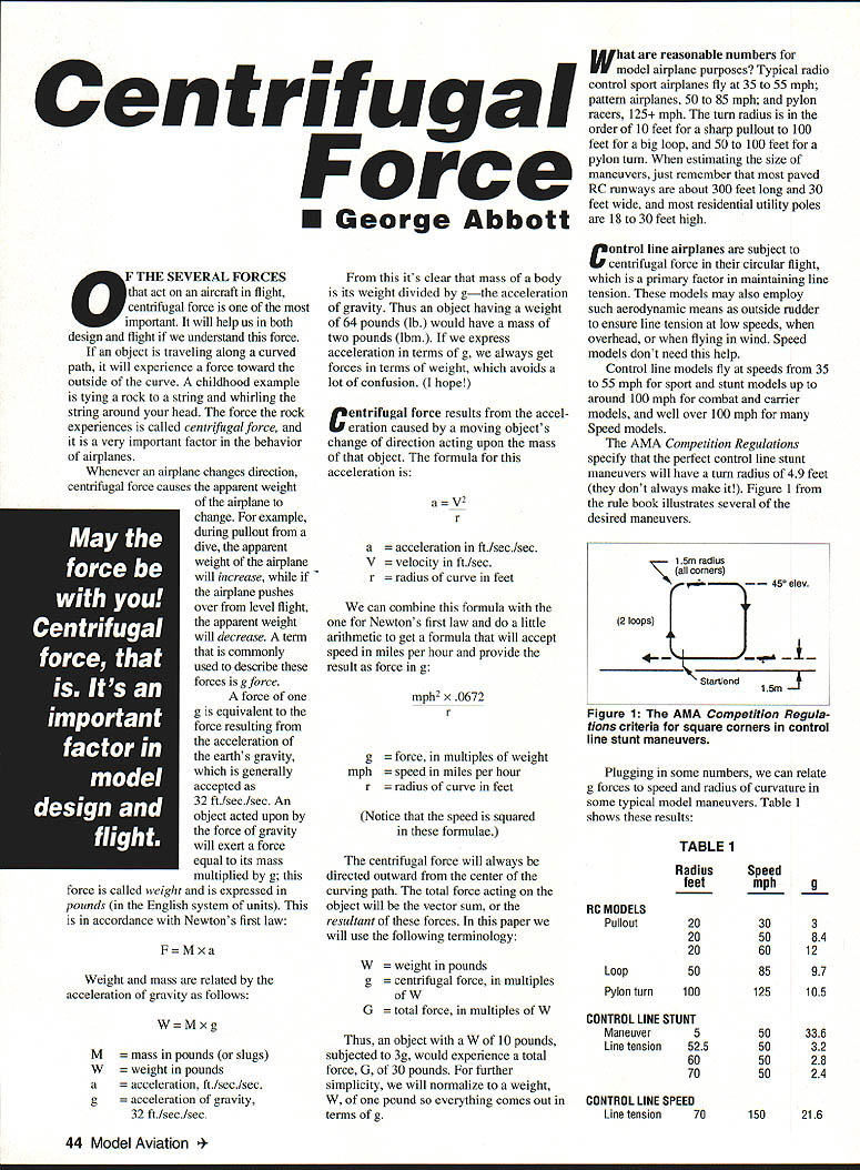
The AMA Competition Regulations specify that the perfect control-line stunt maneuvers will have a turn radius of 4.9 ft (they don't always make it!). Figure 1 in the rule book illustrates several of the desired maneuvers.
Plugging in some numbers, we can relate g forces to speed and radius of curvature in typical model maneuvers. Table 1 shows these results:
TABLE 1 — RC MODELS
- Pullout: radius 20 ft, speed 30 mph → g = 3.0
- Pullout: radius 20 ft, speed 50 mph → g = 8.4
- Pullout: radius 20 ft, speed 60 mph → g = 12.1
- Loop: radius 50 ft, speed 85 mph → g = 9.7
- Pylon turn: radius 100 ft, speed 125 mph → g = 10.5
Examples:
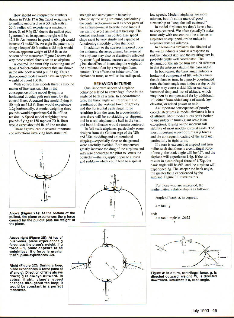
- A Sig Cadet weighing 4.5 lb pulling out of a dive at 50 mph on a 20-ft radius will experience a centrifugal g of 8.4; total G = 9.4 (8.4 due to pullout plus 1g normal). Its apparent weight will be 4.5 × 9.4 = 42.3 lb. An increase to 60 mph would increase total G to about 13.1 and apparent weight to about 59.0 lb.
- An 8-lb pattern ship doing a loop of 50-ft radius at 85 mph (centrifugal g ≈ 9.7; total G ≈ 10.7) would have an apparent weight of about 8 × 10.7 = 85.6 lb at the bottom of the maneuver.
- A control-line stunt ship executing 4.9-ft-radius corners (as in the rule book) might pull about 33.6 g (centrifugal); total G ≈ 34.6. Thus a 3-lb model would have an apparent weight of about 3 × 34.6 ≈ 103.8 lb.
With control-line models there is also the matter of line tension. This is the consequence of the model flying in a horizontal circular path restrained by the control lines. A control-line model flying at 50 mph on 52.5-ft lines would experience 3.2 g horizontally; a 3-lb model would produce about 9.6 lb of line tension. A speed model weighing 3 lb flying at 150 mph on 70-ft lines would exert about 65 lb of line tension.
These figures lead to several important considerations involving both structural strength and aerodynamic behavior. Obviously the wing structure, particularly the center section—as well as other parts of the airframe—must tolerate these loads to avoid in-flight breakup. Control mechanisms in control-line speed ships must be very sturdy and capable of functioning smoothly under that load.
In addition to structural stresses, aerodynamic behavior may be drastically affected by centrifugal forces, because an increase in g increases the effective weight of the airplane. This affects behavior in turns and raises stall speed.
BEHAVIOR IN TURNS
One important aspect of airplane behavior related to centrifugal force is the angle of bank in a turn. In a coordinated turn, the bank angle represents the resultant of the vertical force of gravity and the horizontal centrifugal force from the turn. In a coordinated turn there will be no skidding or slipping; in a real airplane the ball in the turn-and-bank indicator would remain centered.
In full-scale airplanes, particularly some designs from the Golden Age of the 1920s and '30s, skidding and unintentional slipping—especially close to the ground—were carefully avoided. Both maneuvers greatly increase drag and may encourage the pilot to "cross the controls" (apply opposite aileron and rudder), which could lead to a spin at low speeds. Modern airplanes are more tolerant, but it's still a mark of good airmanship to "keep the ball centered."
In model airplanes we don't have a ball to keep centered. We often make turns with one control: the ailerons in airplanes so equipped, or the rudder in airplanes without ailerons. In aileron-less airplanes, wing dihedral induces a bank as a response to rudder-induced skid, and the resulting turn is probably reasonably coordinated. Aileron turns differ in that the ailerons establish the bank angle.
In both cases, the bank angle induces a horizontal component of lift, which causes the airplane to turn. In a poorly coordinated turn, the bank may induce a slip or the rudder may cause a skid. Either can cause increased drag and loss of altitude, which may then be compensated for by added angle of attack (up elevator), added power, or both.
An important consequence of poorly coordinated turns in model airplanes is loss of altitude. Most model pilots don't bother to use rudder in turns (giant-scale is an exception), relying on inherent roll stability to resist skids. The most important aspect of turns is g forces and the consequent loading of the airplane, particularly in tight turns.
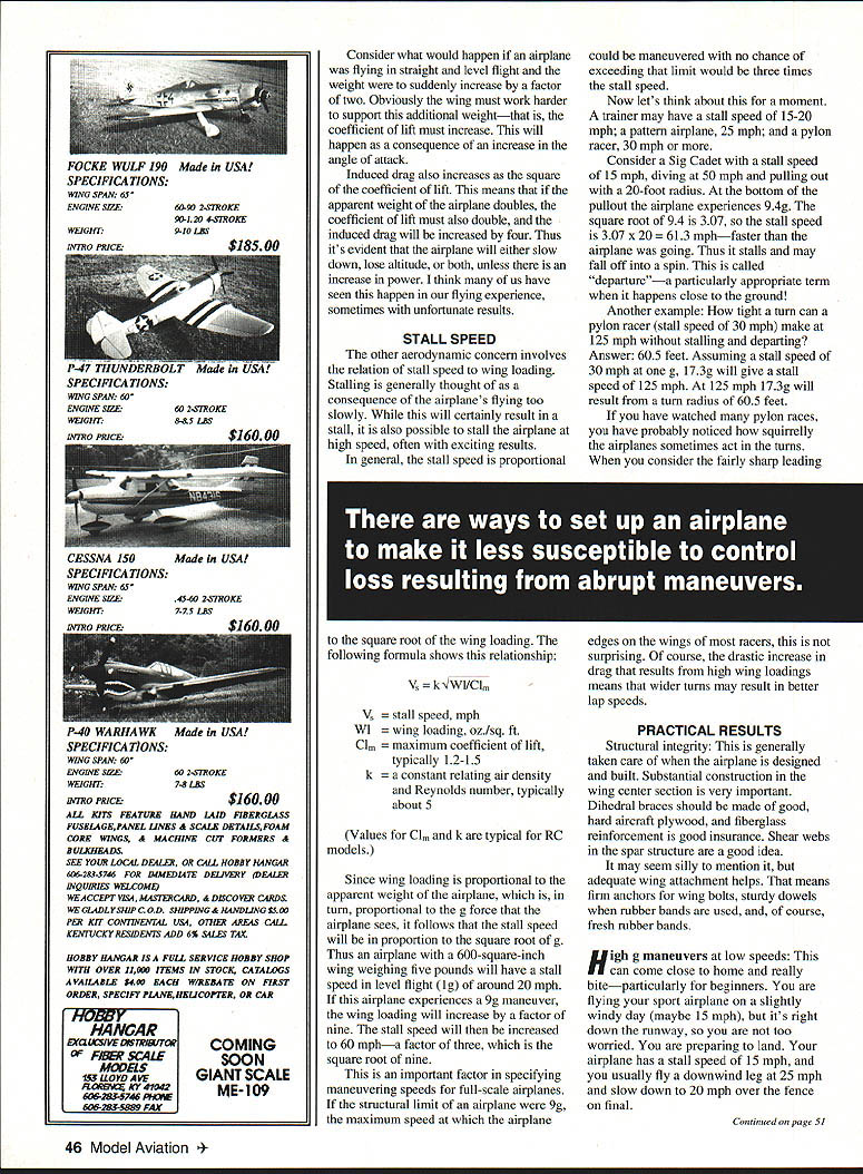
If a turn is executed at a speed and turn radius such that there is a centrifugal force of 1 g, the bank angle will be 45°, and the airplane will experience about 1.414 g (√2). If the turn results in a centrifugal force of 1.73 g, the bank angle will be 60°, and the airplane will experience 2 g. The steeper the bank angle, the greater the g experienced by the airplane.
For those interested, the mathematical relationship is:
Angle of bank, a (degrees): a = tan⁻¹(g)
and, using speed and radius: a = tan⁻¹ ((mph^2 × 0.0672) / r)
Consider what would happen if an airplane flying straight and level suddenly had its effective weight doubled. The wing must work harder to support this additional weight — i.e., the coefficient of lift must increase, which occurs via an increase in angle of attack.
Induced drag also increases approximately as the square of the coefficient of lift. If the apparent weight of the airplane doubles, the coefficient of lift must double and induced drag will increase by four. Thus the airplane will either slow down, lose altitude, or both, unless there is an increase in power. Many of us have seen this happen, sometimes with unfortunate results.
STALL SPEED
Stalling is generally thought of as a consequence of flying too slowly, but it is also possible to stall at high speed if wing loading increases dramatically.
In general, stall speed is proportional to the square root of wing loading. A convenient formula is:
Vs = k × √(Wl / Clm)
- Vs = stall speed, mph
- Wl = wing loading, oz./sq. ft.
- Clm = maximum coefficient of lift (typically 1.2–1.5 for RC models)
- k = constant relating air density and Reynolds number (typically about 5 for RC models)
Since wing loading is proportional to the apparent weight of the airplane, which in turn is proportional to the g force seen, the stall speed varies with the square root of g. Thus, if wing loading increases by a factor of n, stall speed increases by √n.
Example: an airplane with a 600-sq.-inch wing weighing 5 lb will have a stall speed in level flight (1 g) of around 20 mph. If this airplane experiences a 9 g maneuver, the effective wing loading increases by 9, and stall speed increases by √9 = 3, so stall speed becomes about 60 mph.
This is important in specifying maneuvering speeds for full-scale airplanes. If the structural limit were 9 g, the maximum speed at which the airplane could be maneuvered without exceeding that limit would be three times the stall speed.
Examples for models:
- A trainer may have a stall speed of 15–20 mph.
- A pattern airplane, about 25 mph.
- A pylon racer, 30 mph or more.
There are ways to set up an airplane to make it less susceptible to control loss from abrupt maneuvers.
Example: A Sig Cadet with stall speed 15 mph, diving at 50 mph and pulling out within a 20-ft radius. At the bottom of the pullout the airplane experiences total G ≈ 9.4 (8.4 centrifugal + 1 normal). √9.4 ≈ 3.07, so the stall speed becomes 3.07 × 20 mph = 61.3 mph — faster than the airplane's speed in the pullout. Thus it stalls and may depart into a spin. This is called "departure" — especially hazardous close to the ground.
Another example: How tight a turn can a pylon racer (stall speed 30 mph) make at 125 mph without stalling? Answer: about 60.5 ft. At 125 mph, g required to raise stall speed from 30 to 125 mph is (125/30)^2 ≈ 17.36. Plugging g = 17.36 into the radius formula gives r ≈ 60.5 ft.
If you've watched many pylon races you may have noticed how squirrelly the airplanes can be in the turns. With fairly sharp leading edges on many racers this is not surprising. The drastic increase in drag at high wing loadings means that wider turns may result in better lap speeds.
PRACTICAL RESULTS
Structural integrity:
- Build substantial center-section structure into the wing.
- Use good, hard aircraft plywood for dihedral braces; fiberglass reinforcement is good insurance.
- Shear webs in the spar are a good idea.
- Use firm anchors for wing bolts, sturdy dowels when rubber bands are used, and fresh rubber bands.
High-g maneuvers at low speeds:
- These can be dangerous, particularly for beginners.
- Example scenario: flying downwind with a 15 mph wind. Ground speed may be 25 + 15 = 40 mph; you begin to slow and then make a tight turn from downwind to final, inducing additional g loads. The increased g raises wing loading and stall speed while induced drag may slow the airplane further. The result can be a very high sink rate or a snap into the ground.
- Much of the mystique of the "downwind turn" comes from steep turns and speed reductions pilots execute to compensate for wind drift while maneuvering to land.
High-speed stall
There are ways to make an airplane less susceptible to control loss from abrupt maneuvers:
- Proper balance: If an airplane is tail-heavy it will have poor longitudinal stability and be pitch sensitive, making it prone to abrupt maneuvers and high-g events.
- Elevator travel: Set up so that full elevator at any reasonable speed does not immediately cause a high-speed stall. In an emergency pullout close to the ground you don't want the airplane to become uncontrollable because you pulled the stick all the way back.
Control-line tension
In control-line models line tension must be maintained at all times. Line tension results from two factors:
- Centrifugal force (function of speed and radius)
- Aerodynamic factors (rudder offset, leadout position, asymmetrical wing span)
Line tension is usually not a problem except when flying sport or stunt models in strong winds on long lines.
- With 60-ft lines and 50 mph airspeed, centrifugal force is about 2.8 g.
- When directly overhead, line tension is reduced by the downward force of gravity; the vertical component of tension may be only about 1.8 g in some attitudes, but this is usually enough.
- Wind effects: flying upwind reduces airspeed (and thus centrifugal force); crosswind aerodynamic forces counteract centrifugal force on the upwind side of the circle. These two effects do not usually coincide, which helps.
- Example: With 60-ft lines and 50 mph airspeed, centrifugal force = 2.8 g. With a 15 mph headwind, ground speed upwind is 35 mph; formula gives g ≈ 1.37. Relative to 1 g of gravity, the additional centrifugal component is only about 0.37 g. Some aerodynamic line tension from the airplane would be comforting in this case.
CONCLUSION
Model airplanes do not generally fly at scale speeds and are often maneuvered violently. Consequently they are frequently subjected to flight loads far in excess of those encountered by their full-scale counterparts. Fortunately, they are usually much stronger for their size.
The most successful models combine great strength where needed (wing center sections) with light weight, tolerant aerodynamics, proper balance, and conservative trim and adjustment. Pilot skill and a little good luck help, too.
There are also safety considerations. An airplane that tends to go out of control may end up in the pits or among spectators. An airplane that has suffered an in-flight structural failure can also pose a serious safety hazard.
Transcribed from original scans by AI. Minor OCR errors may remain.

