
CERBERUS
Initially designed for flight at 7,000-ft. field elevations, this ship is ideal for the new aerodynamically more difficult FAI maneuvers. The article is a must reading for any Pattern flier.
Dr. Hank Keck
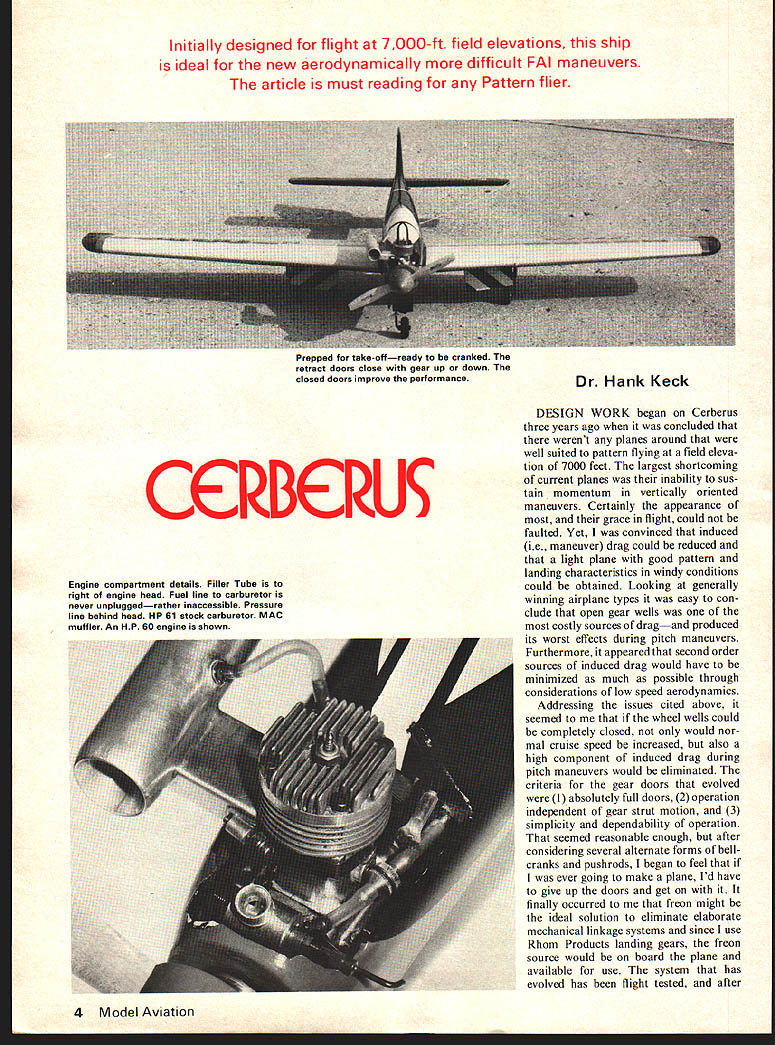
DESIGN WORK began on Cerberus three years ago when it was concluded that there weren't any planes around that were well suited to pattern flying at a field elevation of 7,000 feet. The largest shortcoming of current planes was their inability to sustain momentum in vertically oriented maneuvers. Certainly the appearance of most, and their grace in flight, could not be faulted. Yet, I was convinced that induced (i.e., maneuver) drag could be reduced and that a light plane with good pattern and landing characteristics in windy conditions could be obtained. Looking at generally winning airplane types it was easy to conclude that open gear wells was one of the most costly sources of drag—and produced its worst effects during pitch maneuvers. Furthermore, it appeared that second order sources of induced drag would have to be minimized as much as possible through considerations of low speed aerodynamics.
Addressing the issues cited above, it seemed to me that if the wheel wells could be completely closed, not only would normal cruise speed be increased, but also a high component of induced drag during pitch maneuvers would be eliminated. The criteria for the gear doors that evolved were (1) absolutely full doors, (2) operation independent of gear strut motion, and (3) simplicity and dependability of operation. That seemed reasonable enough, but after considering several alternate forms of bellcranks and pushrods, I began to feel that if I was ever going to make a plane, I'd have to give up the doors and get on with it. It finally occurred to me that freon might be the ideal solution to eliminate elaborate mechanical linkage systems and, since I use Rhom Products landing gears, the freon source would be on board the plane and available for use. The system that has evolved has been flight tested, and after something in excess of 500 flights in two planes, I feel that it can be qualified as reliable, repeatable, and contest dependable.
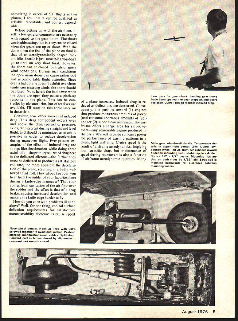
Before getting on with the airplane itself, a few general comments are necessary with regard to the gear doors. The doors are double acting, that is, they can be closed when the gears are up or down. With the doors open the feel of the plane on final is that of an aerodynamically shaped rock and idle throttle is just something you don't go to until on very short final. However, the doors can be closed for high or gusty wind conditions. During such conditions the open main doors can cause rather odd and uncomfortable flight attitudes. Since even a light plane doesn't exhibit overshoot tendencies in strong winds, the doors should be closed. Now, here's the bad news: when the doors are open they cause a pitch-up response in the plane. This can be controlled by elevator trim, but other fixes are available. I'll mention this topic later on in the article.
Consider, now, other sources of induced drag. This drag component occurs over and above the drag (parasitic, pressure, skins, etc.) present during straight and level flight, and should be minimized as much as possible in order to reduce deceleration during maneuver flight. Ever-present examples of the effects of induced drag are things like deceleration while doing three axial rolls—the primary source of drag here is the deflected ailerons—the further they must be deflected to produce a satisfactory roll rate, the more apparent the deceleration of the plane, resulting in a badly wallowed third roll. How about the roar you hear from the rudder of your favorite plane during a knife-edge maneuver? That roar comes from cavitation of the air flow over the rudder and the effect is that of a drag brake, causing increased deceleration and making the knife-edge harder to fly.
How do you cope with problems like the above? Well, for one thing, control surface deflection requirements for satisfactory maneuverability decrease as cruise speed of a plane increases. Induced drag is reduced as deflections are decreased. Consequently, the push is toward (1) engines that produce monstrous amounts of power (and consume enormous amounts of fuel) and/or (2) super-clean airframes. The airframe offers a large area for improvement—any reasonable engine produced in the early 70's will provide sufficient power for performance of existing patterns in a clean, light airframe. Cruise speed is the result of airframe aerodynamics, implying low parasitic drag, but maintenance of speed during maneuvers is also a function of airframe aerodynamic qualities. Many areas of improvement in airframe aerodynamics have been ignored in the past.
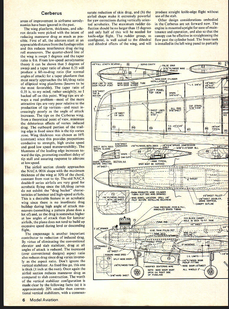
The wing planform, thickness, and aileron details were picked with the intent of reducing maneuver drag as much as possible. First of all, the ailerons start at an appreciable distance from the fuselage sides and this reduces interference drag during roll maneuvers. The quarter-chord line of the wing is swept 5 degrees and the taper ratio is 0.6. From low-speed aerodynamic theory it can be shown that 5 degrees of sweep and a taper ratio of about 0.35 will produce a lift-to-drag ratio (for normal angles of attack) for a taper planform that most nearly approaches the lift/drag ratio of elliptical wing planforms (known to be the most favorable). The taper ratio of 0.35 is, to my mind, rather unsightly, so I backed off on this point. Wing tips are always a real problem—most of the more attractive tips are very poor relative to the production of tip vortices—and react increasingly poorly as the angle of attack increases. The tips on the Cerberus wing, from a theoretical point of view, minimize the deleterious effects of vortex induced drag. The outboard portion of the trailing edge is fixed since this is the tip vortex zone. Wing thickness was chosen as 16% (constant) since this provides proportions conducive to strength, high cruise speed and good low speed maneuverability. The bluntness of the leading edge increases toward the tips, promoting excellent delay of tip stall and assuring response to ailerons at low speed.
The airfoil section closely approaches the NACA 0016 shape with the maximum thickness of the wing at 30% of the chord, constant from root to tip. The old NACA double-0 series airfoils are very good for acrobatic flying since the lift/drag curves do not exhibit the "drag bucket" characteristics of laminar and high-speed airfoils. This is a desirable feature in an acrobatic wing since there is no inordinate drag buildup during the high angle of attack maneuvers (something a pattern plane does a lot of) and, as the drag is somewhat higher at low angles of attack than for laminar airfoils, the plane does not tend to build up excessive speed during level or descending flight.
The empennage is another important contributor to reduction of induced drag. By virtue of eliminating the conventional elevator and slab stabilizer, drag at all angles of attack is reduced. The increased (over conventional designs) aspect ratio also reduces drag since drag varies inversely as the aspect ratio. Don't ignore the vertical stabilizer. As fixed fins go, this one is thick (1 inch at the root). Once again the airfoil section reduces manner drag as compared to slab construction. The worth of the vertical stabilizer configuration is made clear by the following facts: (a) it is approximately 20% smaller than conventional vertical stabilizers, with a commensurate reduction of skin drag, and (b) the airfoil shape makes it extremely powerful for yaw corrections during vertically oriented acrobatics. The maximum rudder deflection should be no larger than 15 degrees and only half of this will be needed for knife-edge flight. The rudder group, as configured, is well suited to the dihedral and dihedral effects of the wing, and will produce straight knife-edge flight without use of the stab.
Other design considerations embodied in the Cerberus are ease of maintenance and operation, and also so that the canopy can be effective in straightening the flow past the cylinder head. The freon tank is installed in the left wing panel to partially offset the muffler weight. Variations in freon weight can be measured in milligrams, at most, and do not cause lateral balance problems in flight. This location eliminates unnecessary wing tip ballast and is dynamically more correct.
There is very little that need be said concerning construction of the plane. However, I'll hit the high spots.
Fuselage
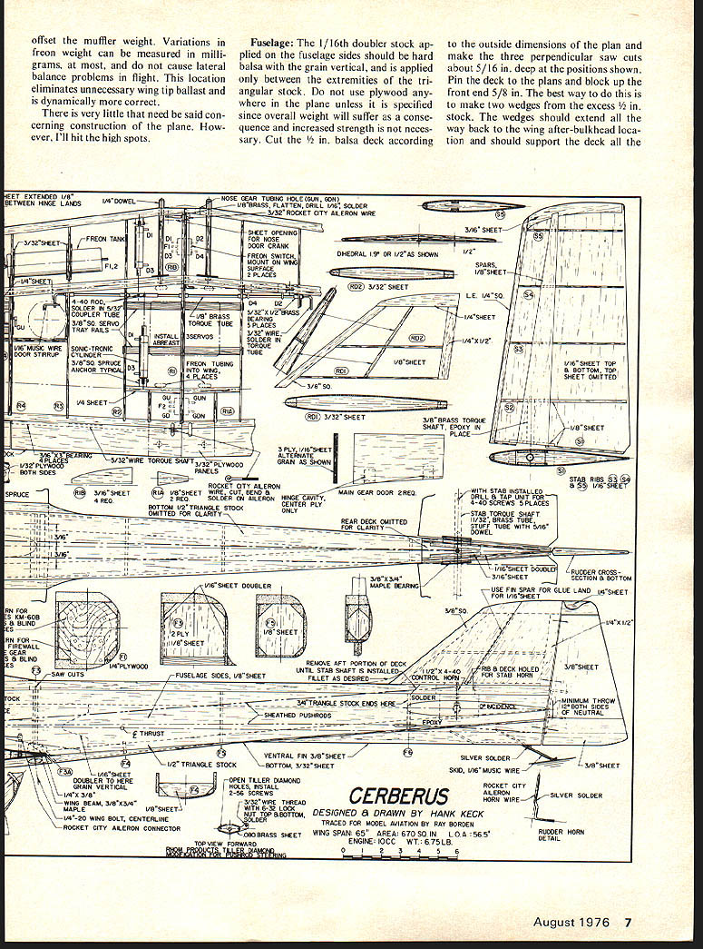
The 1/16th doubler stock applied on the fuselage sides should be hard balsa with the grain vertical, and is applied only between the extremities of the triangular stock. Do not use plywood anywhere in the plane unless it is specified since overall weight will suffer as a consequence and increased strength is not necessary. Cut the 1/2 in. balsa deck according to the outside dimensions of the plan and make the three perpendicular saw cuts about 5/16 in. deep at the positions shown. Pin the deck to the plans and block up the front end 5/8 in. The best way to do this is to make two wedges from the excess 1/2 in. stock. The wedges should extend all the way back to the wing after-bulkhead location and should support the deck all the way back.
Cerberus
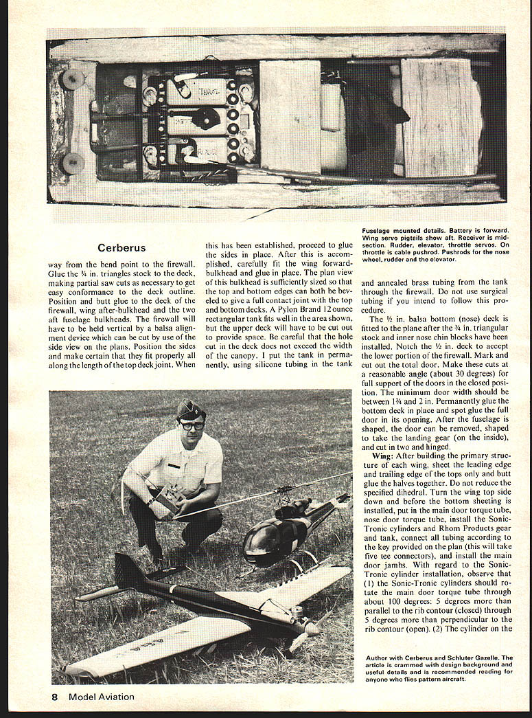
way from the bend point to the firewall. Glue the 3/4 in. triangle stock to the deck, making partial saw cuts as necessary to get easy conformance to the deck outline. Position and butt glue to the deck of the firewall, wing after-bulkhead and the two aft fuselage bulkheads. The firewall will have to be held vertical by a balsa alignment device which can be cut by use of the side view on the plans. Position the sides and make certain that they fit properly all along the length of the top deck joint. When this has been established, proceed to glue the sides in place. After this is accomplished, carefully fit the wing forward-bulkhead and glue in place. The plan view of this bulkhead is sufficiently sized so that the top and bottom edges can both be beveled to give a full contact joint with the top and bottom decks. A Pylon Brand 12 ounce rectangular tank fits well in the area shown, but the upper deck will have to be cut out to provide space. Be careful that the hole cut in the deck does not exceed the width of the canopy. I put the tank in permanently, using silicone tubing in the tank and annealed brass tubing from the tank through the firewall. Do not use surgical tubing if you intend to follow this procedure.
The 1/16 in. balsa bottom (nose) deck is fitted to the plan after the 3/16 in. triangular stock and inner nose chin blocks have been installed. Notch the 1/4 in. deck to accept the lower portion of the firewall. Mark and cut out the total door. Make these cuts at a reasonable angle (about 30 degrees) for full support of the doors in the closed position. The minimum door width should be between 1 3/4 and 2 in. Permanently glue the bottom deck in place and spot glue the full door in its opening. After the fuselage is shaped, the door can be removed, shaped to take the landing gear (on the inside), and cut in two and hinged.
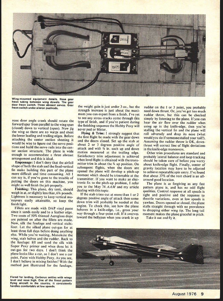
Wing: After building the primary structure of each wing, sheet the leading edge and trailing edge of the tops only and butt glue the halves together. Do not reduce the specified dihedral. Turn the wing top side down and before the bottom sheeting is installed, put in the main door torque tube, nose door torque tube, install the Sonic-Tronic cylinders and Rhom Products gear and tank, connect all tubing according to the key provided on the plan (this will take five tee connectors), and install the main door jambs. With regard to the Sonic-Tronic cylinder installation, observe that (1) the Sonic-Tronic cylinders should rotate the main door torque tube through about 100 degrees: 5 degrees more than parallel to the rib contour (closed) through 5 degrees more than perpendicular to the rib contour (open). (2) The cylinder on the nose door angle crank should rotate the forward spur from parallel to the wing span (closed) down to vertical (open). Now jig the wing so there are no warps and sheet the lower leading and trailing edges. Before attaching the center section sheeting it would be wise to figure out the servo positions and build the servo rails into the center section structure. The plane is wide enough to accommodate a three abreast arrangement and this is ideal.
Empennage
I don't deny that the airfoil shape of both the stab and the fixed vertical fin make building this part of the plane more difficult and time consuming. All I can say is, if you've gone to the trouble of putting the doors on this machine, you might as well finish the job properly.
Finishing
This plane, dry tank, should weigh in at, or slightly less than, 63-1/2 oz. Lightness is necessary to keep vertical maneuvers easily attainable, so keep the finish light. Fillets are made with DAP vinyl paste since it sands easily and to a feather edge. Two coats of 50% thinned Aerogloss dope are painted on after the fillets are made. Now, silk the fuselage and vertical stabilizer. Let the silked plane out-gas for at least three full days before doing anything else. While you're waiting, Monokote the wing, stab halves and the rudder. Back to the fuselage: fill and sand the silk with Super Poxy primer and when done let it out-gas for two days. I don't think the plane looks like a car, so I don't use a car paint. Paint with Hobby Poxy. As you see, I don't believe in mixing finishes! With the method just illustrated for the fuselage, the weight gain is just under 3 oz., but the strength increase is just about the maximum you can expect from a finish. I've yet to see any stress cracks come through this type of finish, and if you're patient during the finishing sequence the Hobby Poxy will never peel or blister.
Flying & Trim
I strongly suggest that the first flight be made with the gear down and the doors closed. Set up the stab at about 2 or 3 degrees positive angle of attack and with 3/4 in. each up and down movement measured at the trailing edge. Satisfactory trim adjustment is achieved when level flight is obtained with the transmitter trim in about the 3/4 up position. On subsequent flights, when the doors are opened the plane will develop a pitch-up moment which should be trimmable at the transmitter. If you want to make an electronic fix to the pitch-up problem, I refer to the May '74 AAM and my article dealing with this topic.
If the stab trims out at more than 1 or 2 degrees positive angle of attack then some down trim will probably be needed at the engine. To check this, see how the plane behaves in a knife-edge, i.e., gross nose way through a four-point roll. If it swerves toward the bellyplane when you crank in the rudder on the 1 or 3 point, you probably need down thrust. Or, you've got too much rudder throw; but this can be checked simply by listening to the plane. If you can hear the air flow over the rudder when using up in the knife-edge, then you're stalling the vertical fin and the plane will roll adversely and drop its nose (what would you do if someone stalled your tail?). Assuming the rudder throw is OK, down-thrust will correct line of flight deviations in the knife-edge maneuvers.
Other trim procedures are standard and probably lateral balance and loop tracking should be taken care of before you worry about knife-edge flight. Finally, center of gravity location may have to be adjusted to achieve repeatable spin entry. I've found that about 37% of the root chord is an all-around good location.
The plane is as forgiving as any fast pattern plane is, and has no odd flight qualities. Control response at all speeds is tight and positive and the response to throttle variations, even at low speeds is yawless. Doors opened or closed, the plane stalls straight through with no prevalence to dropping either wing tip. The long tail moment makes the plane graceful in pitch. Take it out and fly it.
Transcribed from original scans by AI. Minor OCR errors may remain.

