
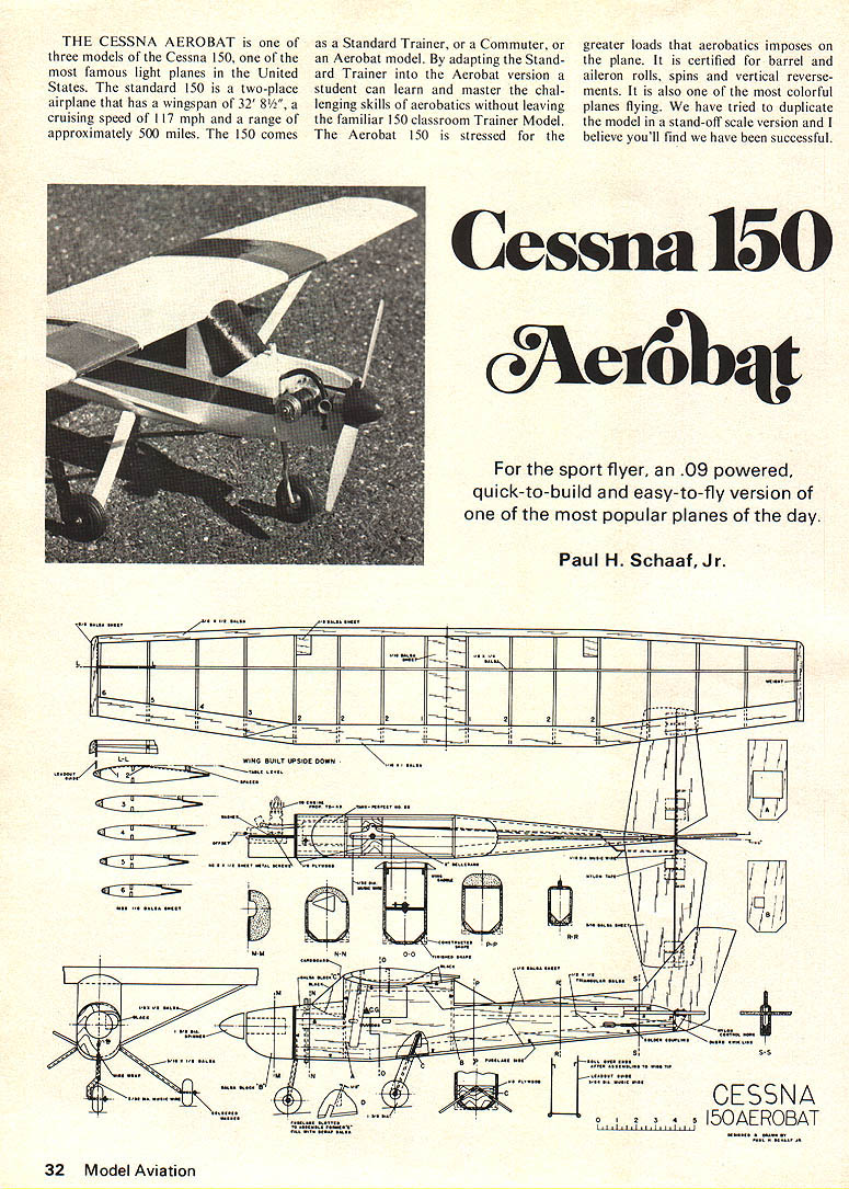
THE CESSNA AEROBAT is one of three models of the Cessna 150, one of the most famous light planes in the United States. The standard 150 is a two-place airplane that has a wingspan of 32' 8½", a cruising speed of 117 mph and a range of approximately 500 miles. The 150 comes as a Standard Trainer, or a Commuter, or an Aerobat model. By adapting the Standard Trainer into the Aerobat version a student can learn and master the challenging skills of aerobatics without leaving the familiar 150 classroom Trainer Model. The Aerobat 150 is stressed for the greater loads that aerobatics imposes on the plane. It is certified for barrel and aileron rolls, spins and vertical reversals. It is also one of the most colorful planes flying. We have tried to duplicate the model in a stand-off scale version and I believe you'll find we have been successful.
Cessna 150 Aerobat
For the sport flyer, an .09 powered, quick-to-build and easy-to-fly version of one of the most popular planes of the day.
Paul H. Schaaf, Jr.
Construction
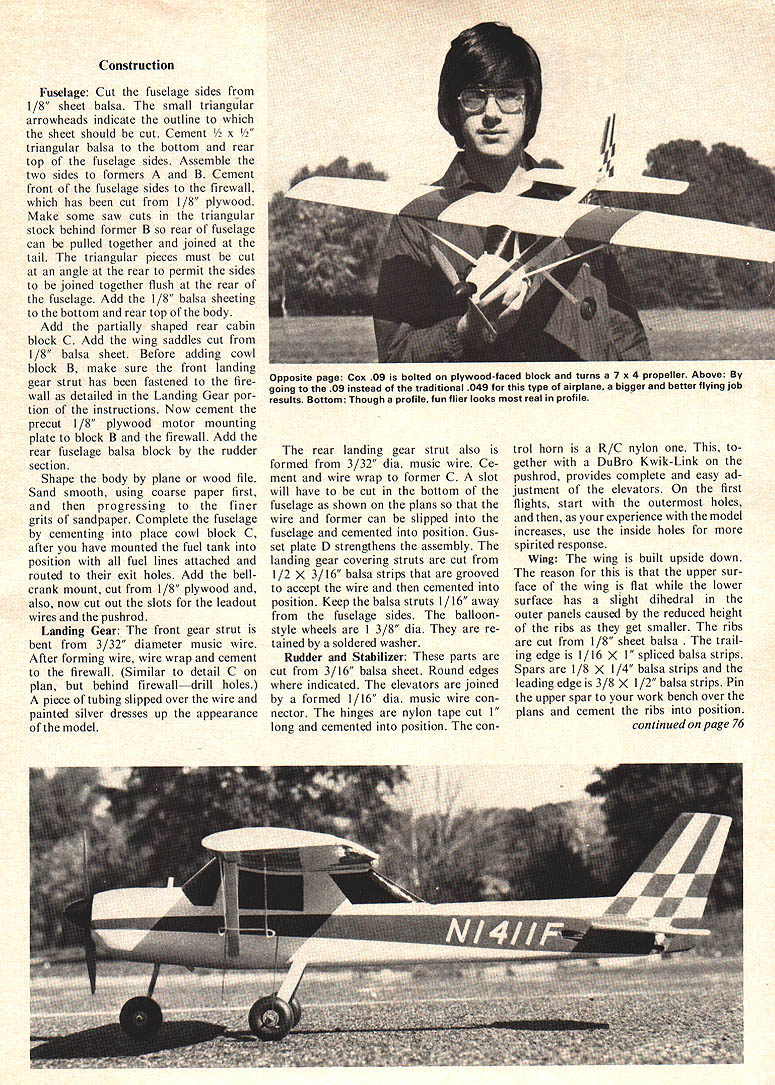
Fuselage: Cut the fuselage sides from 1/8" sheet balsa. The small triangular arrowheads indicate the outline to which the sheet should be cut. Cement 1/2 x 1/2" triangular balsa to the bottom and rear top of the fuselage sides. Assemble the two sides to formers A and B. Cement front of the fuselage sides to the firewall, which has been cut from 1/8" plywood. Make some saw cuts in the triangular stock behind former B so rear of fuselage can be pulled together and joined at the tail. The triangular pieces must be cut at an angle at the rear to permit the sides to be joined together flush at the rear of the fuselage. Add the 1/8" balsa sheeting to the bottom and rear top of the body.
Add the partially shaped rear cabin block C. Add the wing saddles cut from 1/8" balsa sheet. Before adding cowl block B, make sure the front landing gear strut has been fastened to the firewall as detailed in the Landing Gear portion of the instructions. Now cement the precut 1/8" plywood motor mounting plate to block B and the firewall. Add the rear fuselage balsa block by the rudder section.
Shape the body by plane or wood file. Sand smooth, using coarse paper first, and then progressing to the finer grits of sandpaper. Complete the fuselage by cementing into place cowl block C after you have mounted the fuel tank into position with all fuel lines attached and routed to their exit holes. Add the bellcrank mount, cut from 1/8" plywood; also now cut out the slots for the leadout wires and the pushrod.
Landing Gear: The front gear strut is bent from 3/32" diameter music wire. After forming wire, wire wrap and cement to the firewall. (Similar to detail C on plan, but behind firewall—drill holes.) A piece of tubing slipped over the wire and painted silver dresses up the appearance of the model.
The rear landing gear strut also is formed from 3/32" dia. music wire. Cement and wire wrap to former C. A slot will have to be cut in the bottom of the fuselage as shown on the plans so that the wire and former can be slipped into the fuselage and cemented into position. Gusset plate D strengthens the assembly. The landing gear covering struts are cut from 1/2 x 3/16" balsa strips that are grooved to accept the wire and then cemented into position. Keep the balsa struts 1/16" away from the fuselage sides. The balloon-style wheels are 1 3/8" dia. They are retained by a soldered washer.
Rudder and Stabilizer: These parts are cut from 3/16" balsa sheet. Round edges where indicated. The elevators are joined by a formed 1/16" dia. music wire connector. The hinges are nylon tape cut 1" long and cemented into position. The control horn is a R/C nylon on one. This, together with a DuBro Kwik-Link on the pushrod, provides complete and easy adjustment of the elevators. On the first flights, start with the outermost holes, and then, as your experience with the model increases, use the inside holes for more spirited response.
Wing: The wing is built upside down. The reason for this is that the upper surface of the wing is flat while the lower surface has a slight dihedral in the outer panels caused by the reduced height of the ribs as they get smaller. The ribs are cut from 1/8" sheet balsa. The trailing edge is 1/16" x 1" spliced balsa strips. Spars are 1/8" x 1/4" balsa strips and the leading edge is 3/8" x 1/2" balsa strips. Pin upper spar to your work bench over plans and cement ribs in position. Note the two special ribs at the center section that are 1/16" thinner so this area can be sheeted to build up more strength in the stressed center area.
Position spacers under the ribs as illustrated so they all will have the correct angle. Add the lower rear trailing edge, bottom spar and leading edge. Apply 1/16" balsa sheeting to the center area. When wing cement is dry remove from plan and cement into position the upper trailing edge. Add the wing tip blocks and trim to shape. Add the 1/8" sheet balsa attachment plates for the wing struts. Cut a pocket into the right wing-tip block and cement into position several small sinkers. This is to help the model maintain tension on the lines and is one of three techniques used to accomplish this, the others being offset motor and offset rudder.
Assembly and Finishing:
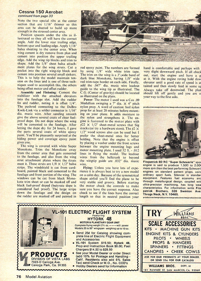
Cement the stabilizer with the attached elevators into the fuselage slot. Add the rudder fin and rudder, noting it is offset 1/4". The pushrod connecting to the DuBro Kwik-Link via a solder connector is 1/16" dia. music wire. After sanding smooth give the above several coats of clear fuel-proof dope. Do not dope where the wing will be cemented to the fuselage. After letting the dope dry for 24 hours, I gave the parts several coats of white epoxy paint. You'll be pleasantly surprised at the hiding power and coverage epoxy paint gives you.
The wing is covered with white Super Monokote. Trim the Monokote away from the center area that gets cemented to the fuselage and also from the wing strut attachment plates where the struts meet it. These struts are 1/8" x 1/2" balsa strips. The windshield is cut from cardboard, painted black and cemented to the fuselage and front portion of the wing. The windows can be cut from black Monokote trim sheet or can be masked off and black fuel-proof doped (butyrate dope is considered fuel proof). The large stripe down the fuselage and the design on the rudder are masked off and painted in red epoxy paint. The numbers are formed by using 1/8" wide white trim tape. The trim on the wing is a 3" wide band of dark blue Monokote, having 1/8" wide red trim-tape border on each side. Finally, add the .047" dia. music wire leadout guide to the wing tip as illustrated. The C.G. (Center of gravity) should be located as illustrated on the plans.
Power:
The motor I used was a Cox .09 Medallion swinging a 7" dia. x 4" pitch nylon prop. A word of caution: boil nylon prop for at least 20 minutes before mounting on your plane. It adds moisture to the nylon and strengthens it. The engine is fastened to the motor plate with #22 x 1/2" sheet-metal screws that Sig stocks (or try a hardware store). The #2 x 1/2" wood screws also can be used but I prefer the sheet-metal ones for better holding. Note that the engine is offset by placing a washer under the front screws between the engine mounting lugs and motor mounting plate. I used 52 ft., .012" lines in flying the model. The leadout wires from the bellcrank to beyond the wingtip guide are .032" dia. music wire.
Flying:
Unless you have lots of experience it is always best to try a new model on a calm day. Because of the symmetrical airfoil you'll find the plane to be very stable and groovy. Before starting the motor check the controls to make sure they have the correct response. Also check to see if the lines have the correct length so that in neutral position your hand is comfortable and perhaps with a very slight downward pitch. If all check out, start the engine and have a good run at it. With the engine revving hold down elevator until a good rate of speed is attained and then slowly feed in some up. Always take off downwind. The plane should lift off gently and you are on your way to the first solo.
Transcribed from original scans by AI. Minor OCR errors may remain.

