
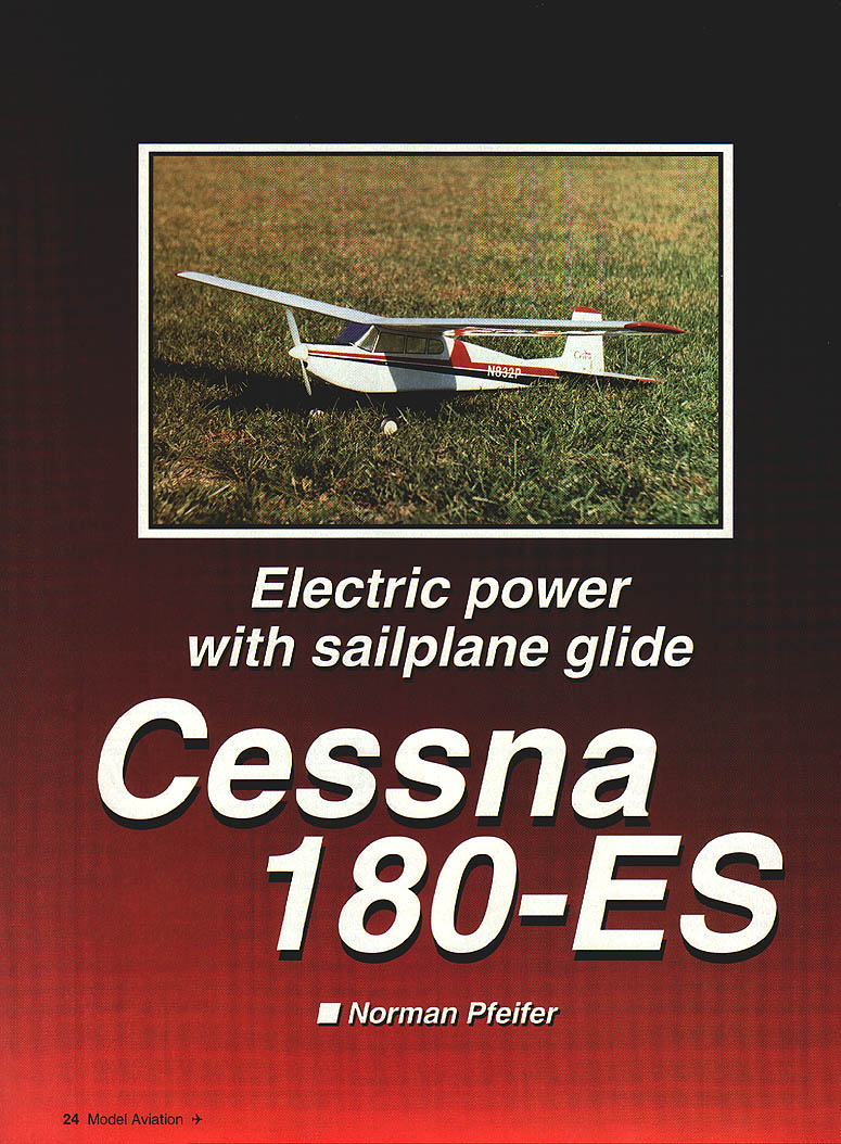
Cessna 180-ES
Electric power with sailplane glide
Norman Pfeiffer
"Wow, Dad—that was a great day of glider flying. Don't you think that I need a new glider to keep up with the big boys, like Jim, Mike, and Gary? I want one with an Eppler 214, reflex, flaps, crow, coupled ailerons and rudder, and all that good stuff!"
"But Jeffrey, the way you fly, I would be doing nothing but chasing the hi-start! You would be better off to get your flying down first."
"Well, Dad, I really think you should think about it, don't you?" (Notice how third-grade psychology has improved over the first grade.)
"But Dad, I want ..."
So there I was, wanting to satisfy eight-year-old Jeffrey; but Jeffrey, "I want ..." Standing at my workbench that night, I looked over at Jeffrey's accumulation of airplanes and saw a rubber-powered Cessna 180. The light went on, and before going to bed at 4:30 that morning, the plans were drawn for Jeffrey's new "glider"—one with an electric motor in the nose that looked like a real airplane.
Three weeks later, off to the flying field we went. After a one-minute burst of power, I was fighting to get the model down. Five thermals later (and with Jeffrey yelling, "Dad, get it down! I want to fly it!") the first 20-minute flight was done. It sure needed some washout in the wingtips, but we knew we had met our goals.
The next time out, a friend who is a commercial pilot (and who had never flown a model before) went with us. Bob and Jeffrey flew the Cessna all afternoon and wouldn't give it back. They had a ball until the last flight, when I demanded a turn. Boy, were they ticked! It was so stable and efficient that they really didn't want to share.
If you have read all the glowing claims as to how great electric flying is, and you are still skeptical, don't be. With modern technology and refinements in construction, aerodynamics, motors, batteries, etc., electric truly has come of age. For good, relaxing flying with no messy cleanup, a simple setup, and no noise, you can't match electric sailplane flying.
The Cessna 180-ES (Electric Sailplane) fills that bill perfectly. The Eppler 214 airfoil is truly efficient—good lift with minimal drag. This allows the model to go higher, faster, and penetrate that nasty wind. However, it must be flown a little faster than the old flat‑bottom airfoils to get it up "on step."
With a wingspan of 62¼ inches and wing area of 492 square inches, it's just the right size to get into the "high air" quickly and is still big enough to glide around for a long time. It will do loops, Immelmanns, stall turns, Cuban eights, spins, and mind-boggling snap rolls. The large stabilizer makes it very stable and relaxing on those long thermal flights.
It has used everything from a worn-out Leisure .05 to an Astro .05 Cobalt, and when coupled with either six or seven cells and an old Top Flite 8 x 4 prop, it can get aloft swiftly.
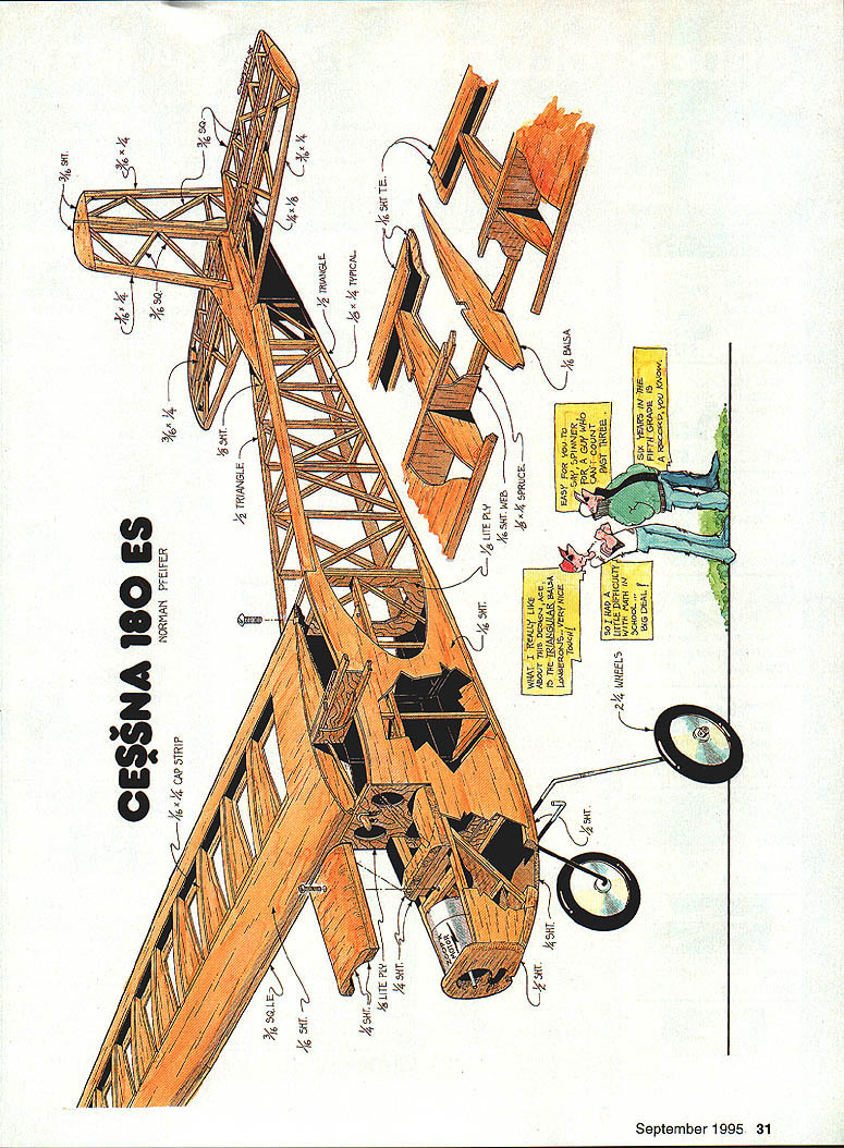
Construction
The Cessna is built in a fashion similar to many Old-Timer models. It's important to build with precision, accuracy, and lightness for a superior airplane.
Stab and rudder
I usually start here, because these parts are quicker to complete and they give me a feeling that I've done something.
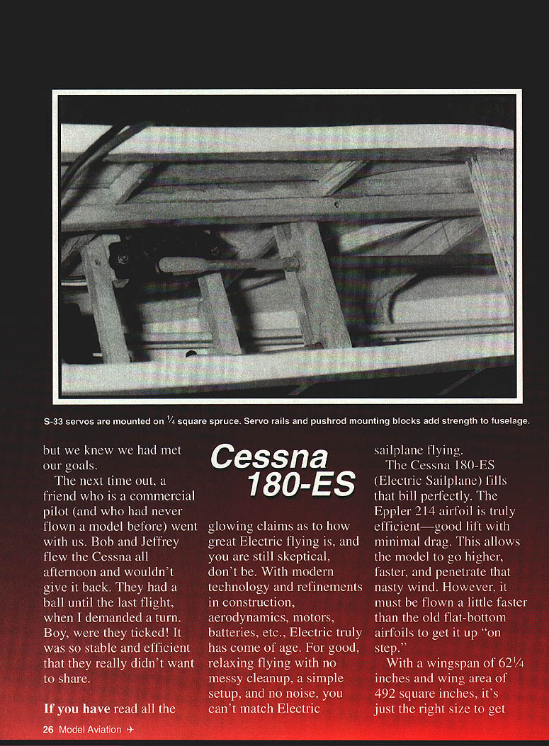
Use soft balsa for the tail feathers. The 3/16 x 1/4 outline framing is best done by laminating 3/32 x 1/4 balsa strips with a 1/16 piece using CyA glue. This provides a more rigid frame that is less prone to breakage and warping but is still light.
Add the top and bottom spars over the flat stabilizer. Add the center ribs of tapered 1/8 x 1/4 where the rudder will set in. Wait to install the bottom center ribs until the fuselage is completely shaped, then align the stabilizer.
Mark the fuselage outline on the bottom of the stabilizer so the bottom center ribs can be positioned at just the right angle to fit down over the fuselage side. The top and bottom spars on the stabilizer create a diamond airfoil when the covering is applied. This airfoiled stabilizer will have greater efficiency than a stabilizer that is flat.
Wing
The wing is best constructed using a hinged building board so that the dihedral angle can be established and the wing built in one piece.
The spar is less thick at the tip, where great strength is not required (and saving weight is important). The greater spar thickness is inboard, where more strength is required.
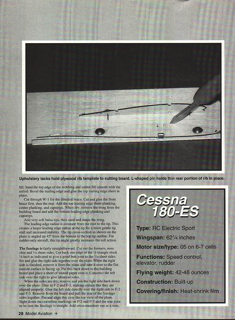
The center ribs are cut using a 1/16 plywood template. Set the template over a piece of particleboard and drill two 1/16 holes (one near the leading edge, one near the trailing edge) through the template and board. Place large upholstery tacks in these holes and CyA them to the plywood; this gives a key for cutting the ribs. Place the template over a balsa blank and key into the particleboard. Trim around the template to cut the rib. After a couple of passes, the blade will scribe a groove in the particleboard, which will help guide the blade in future cuts and aid in making a matched set of ribs.
Since there are only two of each tip rib, the easiest way to reproduce them is the punch‑through‑the‑plan technique. Place a copy of the rib over the balsa sheet, and poke through the rib outline every 1/4 inch. Set the rib pattern over another balsa sheet and poke through the holes already created. Connect the holes and the ribs are ready to be cut.
Place waxed paper over the ribs, pin the bottom spar in place, and add the rib shims. This airfoil has an undercambered section at this point and must be supported.
Pin the bottom trailing edge 3/8 inch from the trailing edge. The forward portion of the trailing edge must be lifted up when gluing to the ribs. CyA the trailing edge at the tip, then the center, then the root; divide the remaining distances by half until all ribs are glued.
Add the leading edge and top spar. Glue in the trailing edge webbing, the main spar webbing, and the center trailing edge sheeting. This airfoil has an undercambered section at this point and must be supported until dry.
Add the leading edge cap and sand to shape. Glue in the wing fillets and fair the wing to the tips. Fill and sand the top edge of the webbing and center fill smooth with the airfoil. Bevel the trailing edge and glue the top trailing edge sheet in place.
Cut through W-1 for the dihedral brace. Cut and glue the front brace first, then the rear. Add the top leading edge sheet planking, center planking, and capstrips. Dry-fit, remove the wing from the building board, and add the bottom leading edge planking and capstrips.
Add very soft balsa tips, then sand and shape the wing.
The leading edge radius is constant from the root to the tip. This creates a larger effective leading edge radius at the tip for a more gentle tip stall and increased stability. The tip cross-section as shown on the plans is angled up 45° from the bottom to the top tip outline. For rudder-only aircraft, this tip angle greatly increases the roll action.
Fuselage
The fuselage is fairly straightforward. Cut out the formers, nose chin, and 1/16 sheet sides. Cut back one edge of the 1/2 triangle stock 1/16 inch as indicated to give a good butt joint to the 1/16 sheet sides. Set and glue the right side together over the plans. When the right side is finished, remove it from the plans and turn it over so the flat outside surface is facing up. Pin this back down to the building board and place a sheet of waxed paper over it. Construct the left side over the right to give identical sides.
When the sides are dry, remove and pin the right side back down over the plans. Glue in F-2 and F-3, making certain that they are aligned properly. Glue the left side directly over the right side to F-2 and F-3. Remove from the board and pull the rear of the fuselage sides together. Pin and align this over the top view of the plans. Sight down the centerline markings on F-2 and F-3 and the rear joint to be sure the fuselage is straight. Add cross-members one at a time, double-checking for straightness and no twist.
Pull the nose together and glue in F-1. There is no side thrust built in; downthrust was predetermined when the sides were fabricated.
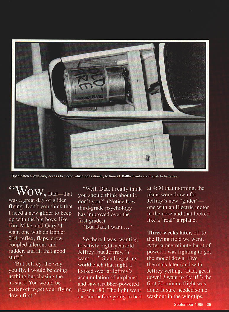
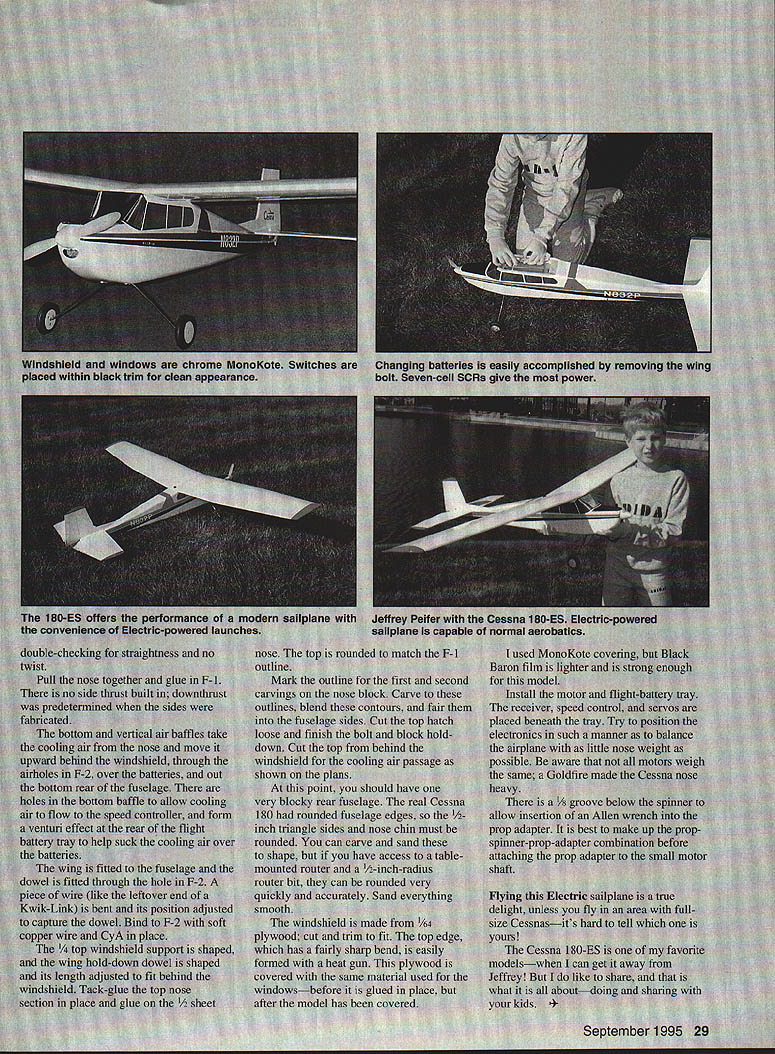
The bottom and vertical air baffles take the cooling air from the nose and move it upward behind the windshield, through the airholes in F-2, over the batteries, and out the bottom rear of the fuselage. There are holes in the bottom baffle to allow cooling air to flow to the speed controller, and they form a venturi effect at the rear of the flight battery tray to help suck the cooling air over the batteries.
The wing is fitted to the fuselage and the dowel is fitted through the hole in F-2. A piece of wire (like the leftover end of a Kwik‑Link) is bent and its position adjusted to capture the dowel. Bind to R-2 with soft copper wire and CyA in place.
The V‑top windshield support is shaped, and the wing hold‑down dowel is shaped and its length adjusted to fit behind the windshield. Tack‑glue the top nose section in place and glue on the 1/64 sheet nose. The top is rounded to match the F-1 outline.
Mark the outline for the first and second carvings on the nose block. Carve to these outlines, blend these contours, and fair them into the fuselage sides. Cut the top hatch loose and finish the top and block hollowing down. Cut the top from behind the windshield for the cooling air passage as shown on the plans.
At this point, you should have one very blocky rear fuselage. The real Cessna 180 had rounded fuselage edges, so the 1/16-inch triangle sides and nose chin must be rounded. You can carve and sand these to shape, but if you have access to a table-mounted or benchtop router and a 1/2-inch radius router bit, they can be rounded very quickly and accurately. Sand everything smooth.
The windshield is made from 1/64 plywood, cut and trimmed to fit. The top edge, which has a fairly sharp bend, is easily formed with a heat gun. This plywood is covered with the same material used for the windows before it is glued in place, but after the model has been covered.
I used MonoKote covering, but Black Baron film is lighter and strong enough for this model.
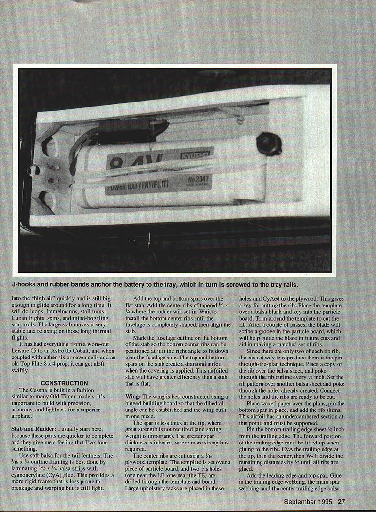
Install the motor and flight-battery tray. The receiver, speed control, and servos are placed beneath the tray. Try to position the electronics in such a manner as to balance the airplane with as little nose weight as possible. Be aware that not all motors weigh the same; a Goldfire made the Cessna nose heavy.
There is a 3/8" groove below the spinner to allow insertion of an Allen wrench into the prop adapter. It is best to make up the prop-spinner-prop-adapter combination before attaching the prop adapter to the small motor shaft.
Flying this electric sailplane is a true delight, unless you fly in an area with full‑size Cessnas — it's hard to tell which one is yours!
The Cessna 180-ES is one of my favorite models — when I can get it away from Jeffrey! But I do like to share, and that is what it is all about — doing and sharing with your kids.
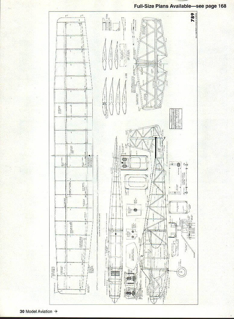
Full‑size plans available — see page 168.
Specifications
- Type: RC Electric Sport
- Wingspan: 62¼ inches
- Wing area: 492 square inches
- Motor size/type: .05 on 6–7 cells
- Functions: Speed control, elevator, rudder
- Flying weight: 42–48 ounces
- Construction: Built-up
- Covering/finish: Heat-shrink film
Materials / Notes
- 1/16 x 1/4 cap strip
- 1/16 triangle
- 1/8 lite ply
- 1/8 sheet
- 1/16 balsa
- 1/4 x 1/4 spruce
- 2-1/4" wheels
Norman Pfeiffer
Transcribed from original scans by AI. Minor OCR errors may remain.

