
Cessna Bird Dog II
Olin Brown
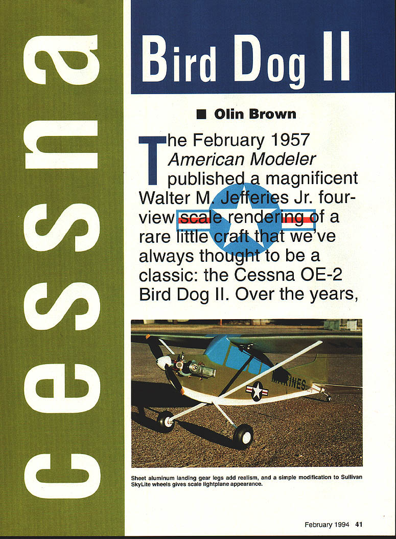
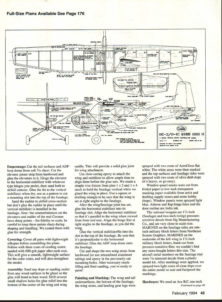
The February 1957 American Modeler published a magnificent Walter M. Jefferies Jr. four-view scale rendering of a rare little craft that we've always thought to be a classic: the Cessna O-1E Bird Dog II. Over the years, our copy of this drawing was shuffled from house to house and drawer to drawer, but it kept popping up to remind us that someday we ought to model this striking little plane. Well, after thirty-something years of faithful reminding, we finally recovered the little dog-eared Jefferies drawing and decided that someday had arrived!
We've always admired the lines of Cessna's 180 and O-1, with their squared tips and tall, angular vertical stabilizers. We wanted a model that closely resembled the O-1E but wasn't too tedious or time-consuming to build, so we decided on a profile type in a one-inch-to-the-foot scale.
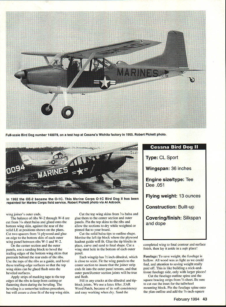
The outlines of the fuselage, wing and tail surfaces are as close to scale as we could reproduce them. This model has a hollow fuselage to save weight; the fuselage is a 1/4-inch sheet-balsa profile spine covered with markings. The Squadron/Signal Publications book O-1 Bird Dog in Action, by Al Adcock, has excellent photos of O-1s and we recommend it as a source for the history of the Bird Dog family.
CONSTRUCTION
Construction is fairly simple, but study the plans and read this article before starting. Pay constant attention to saving weight, particularly in the fuselage and tail. Anything tail-heavy will be a drag!
Wing
The wing outline is scale, but the airfoil isn't. The O-1E's NACA 2412 airfoil had an upswept bottom surface, but our model's wing has a flat underside for ease of construction.
- Trace the wing bottom-skin outline onto 1/16-inch sheet balsa and cut it out. Use either a 6 x 36 sheet or two narrower sheets edge-glued together.
- Pin the bottom wing skin flat onto your building board. Glue a 5/8 x 1-inch solid-balsa wing leading edge (LE) down onto the bottom skin with 3/8 inch of the solid LE protruding beyond the edge of the skin. Pin or weight the solid LE onto the bottom skin for a tight glue joint.
- Make a template of the airfoil cross section at the center-section LE and use it to partially shape the entire wing LE. Shape LE sweepback on the outer wing panels. Trim the bottom skin/LE to the correct span.
- Cut the bottom skin/LE unit at the dihedral-break lines with a razor saw to yield the center section and two outer panels.
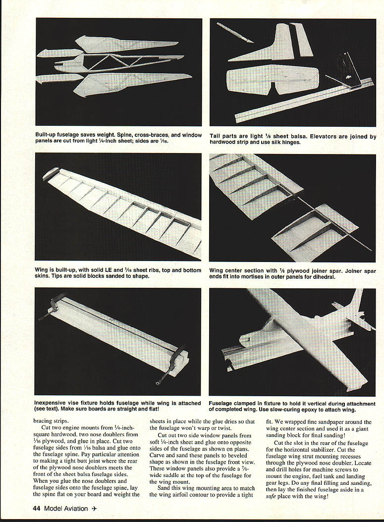
Cut the wing joiner from 1/8-inch plywood and glue onto the center section against the rear of the LE. Cut six ribs W-1 from 1/16-inch sheet balsa and glue onto the bottom skin against the rear wing joiner in the center section. Two W-1s glued together are glued to the bottom skin against the rear wing joiner in the middle of the center section.
Cut the bellcrank platform from 1/8-inch plywood and glue onto the bottom skin. Glue a balsa filler block onto the bellcrank platform and shape the airfoil contour so the top skin will fit flush over it. The remaining two W-1s are glued onto the bottom skin at the inboard end of each outer wing panel. Note the 1/8-inch gap between the front ends of the W-1 ribs and the solid LE which allows space for the plywood components.
Cut W-2 through W-8 balance ribs from 1/16-inch sheet balsa and glue onto the bottom wing skin against the rear of the solid LE at the positions shown on the plans. Cut two spacers of 1/8-inch plywood and glue to the edge of the bottom skin of the outer wing panel between ribs W-1 and W-2.
In the center-section outer panels, use a sanding block to bevel the trailing edges so the bottom wing skins protrude behind the rear ends of the ribs. Use the top ribs as a guide to bevel the trailing-edge surfaces so the top wing skins can be glued flush onto the beveled surfaces.
Apply strips of masking tape to the top edges of the ribs to keep them from chipping during beveling — beveling is somewhat tedious but assures a close fit of the top skins. Cut the top wing skins from 1/16-inch balsa and glue to the center section and outer panels. Pin the top skins to the ribs and allow sections to dry while weighted and pinned flat to the building board.
Cut solid balsa tips to the outline shape. Mortise the left tip block for the plywood leadout guide and fit. Glue the tip blocks in place and carve and sand to the final shape. Cut the wing strut hole in the bottom outer panel. The wingtip has 1/2-inch dihedral to be close to scale. Fit the wing panels to the center section and ensure the joiner strip ends fit the outer-panel tenons so the outer-panel/center-section joints will true flush. Fill cracks in the dihedral tip-block joints with latex filler.
We use a latex filler (ZAR Wood Patch) because of its soft consistency and easy sanding when dry. Sand the completed wing to final contour and surface finish, then lay it aside in a safe place.
Fuselage
To save weight, the fuselage is hollow. All wood should be as light as possible; attention to saving weight really pays off. This is like building a stick-and-tissue fuselage, only with larger pieces.
- Cut the fuselage outline spine and the square-bracing strips from 1/4-inch sheet. Be sure to cut out the inset for the tailwheel mounting block.
- Pin the fuselage spine onto the plan outline and add the 1/4-inch-square longerons and the 1/8-inch cross strips. Glue the cross pieces in place and fit the plywood firewall and landing-gear mount.
- Sheet-aluminum landing gear legs add realism; Sullivan SkyLite wheels give a scale lightplane appearance.
Cut the formers and side doublers from 1/16-inch and 1/8-inch sheet as shown on the plans and glue in place. Fit the cockpit coaming formers and glue in the top and bottom sheeting. Carve and sand the nose and turtledeck to shape. Install the plywood tailwheel mounting plate and the tailwheel assembly, then fit and shape the tail-skid area.
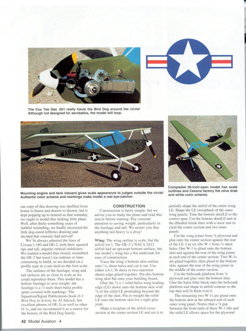
Install the bellcrank, pushrods and control linkages making sure the throws are correct and that all controls move freely. Mount the fuel tank and the engine on the firewall. Balance the model as shown on the plans — pay strict attention to keeping the tail light.
Cut two engine mounts from 1/4-inch-square hardwood. Cut nose doublers from 1/16-inch plywood and glue in place. Cut two fuselage sides from 1/16-inch balsa and glue onto the fuselage spine. Pay particular attention to making a tight butt joint where the rear of the plywood nose doublers meets the front of the sheet balsa fuselage sides. When you glue the nose doublers and fuselage sides onto the fuselage spine, lay the spine flat on your board and weight the sheets in place while the glue dries so that the fuselage won't warp or twist.
Cut out two side window panels from soft 1/4-inch sheet and glue onto opposite sides of the fuselage as shown on plans. Carve and sand these panels to beveled shape as shown in the fuselage front view. These window panels also provide a 7/8-inch-wide saddle at the top of the fuselage for the wing mount.
Sand this wing-mounting area to match the wing airfoil contour to provide a tight fit. We wrapped fine sandpaper around the wing center section and used it as a giant sanding block for final sanding.
Cut the slot in the rear of the fuselage for the horizontal stabilizer. Cut the fuselage wing-strut mounting recesses through the plywood nose doubler. Locate and drill holes for machine screws to mount engine, fuel tank and landing-gear legs. Do any final filling and sanding, then lay the finished fuselage aside in a safe place with the wing.
Empennage
Cut the tail surfaces and ADF loop dome from soft 3/16-inch sheet. Cut the elevator joiner strip from hardwood and glue the elevators to it. Hinge the elevator to the horizontal stabilizer with whatever type hinges you prefer, then sand both to airfoil contour. Glue the fin to the vertical stabilizer; when dry, use it as a pattern to cut a mounting slot into the top of the fuselage.
Sand the rudder to airfoil cross-section but don't glue the rudder in place until the vertical stabilizer is installed in the fuselage. Note: the counterbalances on the elevators and rudder of the real Cessnas have sharp points — for fidelity to scale, be careful to keep these points sharp during shaping and handling. We coated them with glue for strength.
Covering
Cover all parts with lightweight Silkspan before assembling the plane. Follow with three coats of sanding sealer, sanding with 600-grit paper after each coat. This gives a smooth, lightweight surface for the color coats and also strengthens the model.
Assembly
Sand any dope or sanding sealer from any wood surfaces to be glued so the glue will bond to bare wood. Drill several small shallow holes for glue relief into the bottom center of the wing and wing saddle. This will provide a solid glue joint for wing attachment.
Use slow-curing epoxy to attach the wing and stabilizer to the fuselage. Allow time to align them before the glue sets. We made a simple vise fixture from pine 1 x 2 and 1 x 4 stock to hold the fuselage vertical while we glued the wing in place. Use a square or drafting triangle to be sure that the wing is set at right angles to the fuselage.
After the wing/fuselage joint has set, glue the horizontal stabilizer into its fuselage slot. Align the horizontal stabilizer so that it's parallel to the wing when viewed from front and rear. Align the hinge line at right angles to the fuselage, as you did the wing.
Glue the vertical stabilizer/fin into the slot in the top of the fuselage. Be sure that it's perpendicular to the horizontal stabilizer. Glue the ADF loop dome onto the fuselage.
Cut and shape the two wing struts from hardwood (or use streamlined aluminum tubing) and epoxy them in the previously-cut mounting holes. After necessary crack-filling and final sanding, you're ready to paint.
Painting and Marking
The wing and tail undersurfaces, the bottom of the fuselage, the wing struts, and landing gear legs were sprayed with two coats of AeroGloss flat white. The white areas were then masked and the top surfaces and fuselage sides were sprayed with two coats of olive-drab dope (it's heavy, so go easy).
Window-panel masks were cut from frisket paper (a low-tack transparent masking paper available from artist and drafting supply stores and some hobby shops). Window panels were sprayed light blue. Aileron and flap hinge lines and the door outline are India ink.
The national insignia are 1/2-inch (fuselage) and two-inch (wing) pressure-sensitive decals from Sig Manufacturing Co., and are very close to scale sizes. "MARINES" on the fuselage sides are one-inch military block letters from Northeast Screen Graphics. "MARINES" on the underside of the left wing is 1/2-inch military block letters, hand-cut from pressure-sensitive film; we couldn't find any store-bought letters this size. The aircraft serial numbers on the fuselage rear were 5/16-inch numerals cut from a plastic model kit. After markings were applied, we sprayed two light coats of clear dope over the entire model to seal and fuelproof the markings.
Hardware
- We used an Ace R/C one-inch plastic spinner for a realistic effect.
- The military-specified flat-black propellers with the outermost four inches orange-yellow were simulated by painting a black plastic prop for show.
- Wheels are 1 3/4-inch Sullivan SkyLites modified to simulate scale wheels:
- Countersink the outboard axle hub to accept a one-inch 4-40 flathead machine-screw axle.
- Cut discs of thin sheet plastic or card for inboard hub covers; drill or punch out the hole for the axle and glue in place.
- Install the axles in the wheels, screw head to the outside, and mount the wheels onto the landing-gear legs with a flat washer and a nut between the wheel and the leg and a locknut on the inside of the leg.
- For the outboard hubcaps, use convex white plastic buttons from a sewing shop. After a little sanding they fit snugly in the wheel hub and can be glued in place.
- Paint the Sullivan wheel hubs white for scale appearance.
Install the landing-gear legs with machine screws, which should complete the assembly of the model.
Flying
As with any flying craft, model or full-size, run a preflight check to ensure that all nuts, bolts, screws, pushrods, fuel lines, propeller screws, flying lines, etc., are secure. Be sure that the center of gravity is within at least 1 1/4 inches of the wing leading edge. The model has a long tail moment, and the little Tee Dee .051 doesn't weigh much, so be sure that it isn't tail-heavy!
We flew the model with 1/4A fuel, a Cox gray plastic 6 x 4 propeller, and 35-foot Sullivan lines, and were somewhat surprised at how fast the Cox Tee Dee hauled the 'Dog around the circle—plenty of power there! Longer lines should pose no problem, even with a slight wind.
The model will fly itself off the deck as very stable. The only flight situation to watch is its tendency to float on landing approach—that yard-wide wing just wants to keep flying!
This model was a thoroughly enjoyable and satisfying project. Remember to always fly safely!
Specifications
- Type: CL Sport
- Wingspan: 36 inches
- Engine size/type: Tee Dee .051
- Flying weight: 13 ounces
- Construction: Built-up
- Covering/finish: Silkspan and dope
Transcribed from original scans by AI. Minor OCR errors may remain.

