
Cessna Cardinal
By Allen Wulf
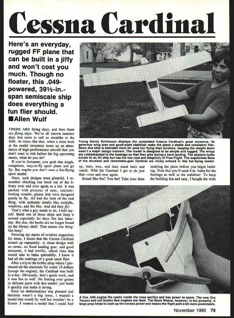
Here's an everyday, rugged FF plane that can be built in a jiffy and won't cost you much. Though no floater, this .049‑powered, 39½‑in.‑span semiscale ship does everything a fun flier should.
There are flying days, and then there are flying days. We've all known summer days that seem to call us siren‑like to the field. At times like that, when a close look at the model inventory turns up an abundance of high‑performance aircraft that you don't want to risk before the big upcoming meets, what do you do?
If you're fortunate, you grab that tough, competent, easy‑to‑fly sport plane and go fly. But maybe you don't own a fun‑flying sport model.
Once, such designs were plentiful. I remember checking one book out of the library over and over again as a kid. It was packed with pictures of neat, realistic‑looking models, planes that were designed purely to fly. All had the look of the real thing, with authentic details like cockpits, windows, and the like. And did they fly! That's what a guy needs to do, I told myself. Build one of those ships and keep it around especially for days like last Saturday. But alas, the books are no longer found on the library shelf. That means one thing: get busy!
Perusing my stacks of aviation magazines for ideas, I found that the Cessna Cardinal turned up repeatedly. A clean design with no struts, no fixed landing gear, and good moments, it had terrific, rakish lines that would take balsa splendidly. I knew it had all the makings of a great sport flier.
After a trip to the hobby shop where I purchased all the materials for under $10 (except the engine), the Cardinal was built in a day. Obviously, that's quick work, and it was fun as well. No fretting over grams or delicate parts with this model; just build it quickly and make it strong.
Since no dethermalizer was planned and duration wasn't a big issue, I wanted a model that would fly well but wouldn't be a floater. I wanted a model that I could fuel up, start, toss, and then stand back and watch. With the Cardinal I get to do just that—over and over again.
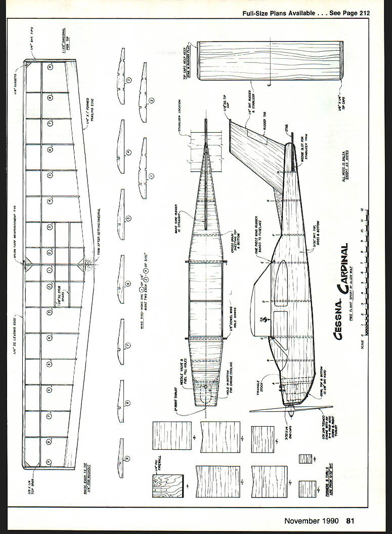
Sound like fun? Take your time studying the plans before you begin building. You'll need 4‑in. balsa for the fuselage as well as the stabilizer; to keep building fun and easy, buy the wide balsa rather than joining matched 3‑in. sheets. Select medium‑lightweight wood. Even more important is its flatness; the rudder and stabilizer must be flat and warp‑resistant.
Materials and tools
- Medium‑lightweight, flat balsa (4‑in. sheets for fuselage and stabilizer)
- 1/8‑in., 3/32‑in., and 1/4‑in. sheeting
- CyA (cyanoacrylate) glue and slow‑dry wood glue
- Small triangular engine‑mount reinforcements (solid wood)
- 8 x 4 wood propeller (bushed to fit engine shaft)
- Plastic heat‑shrink covering or tissue and dope
- Small dowels for wing hold‑down and optional wing keys
- Small medical syringe for metering fuel
- Basic modeling tools (razor saw, sanding blocks, pins, heat gun/iron)
Construction — general tips
Cut out all parts in advance rather than making them one at a time; this expedites the build. Using a good CyA speeds things along, too. Glue the tip caps on the rudder, stabilizer, and fuselage fronts first. Give the tail a good sanding, round the leading and trailing edges, and set the parts aside on a flat surface.
Fuselage
- Pin the fuselage sides together over the plan top view. Mark former locations and cut the stabilizer slot.
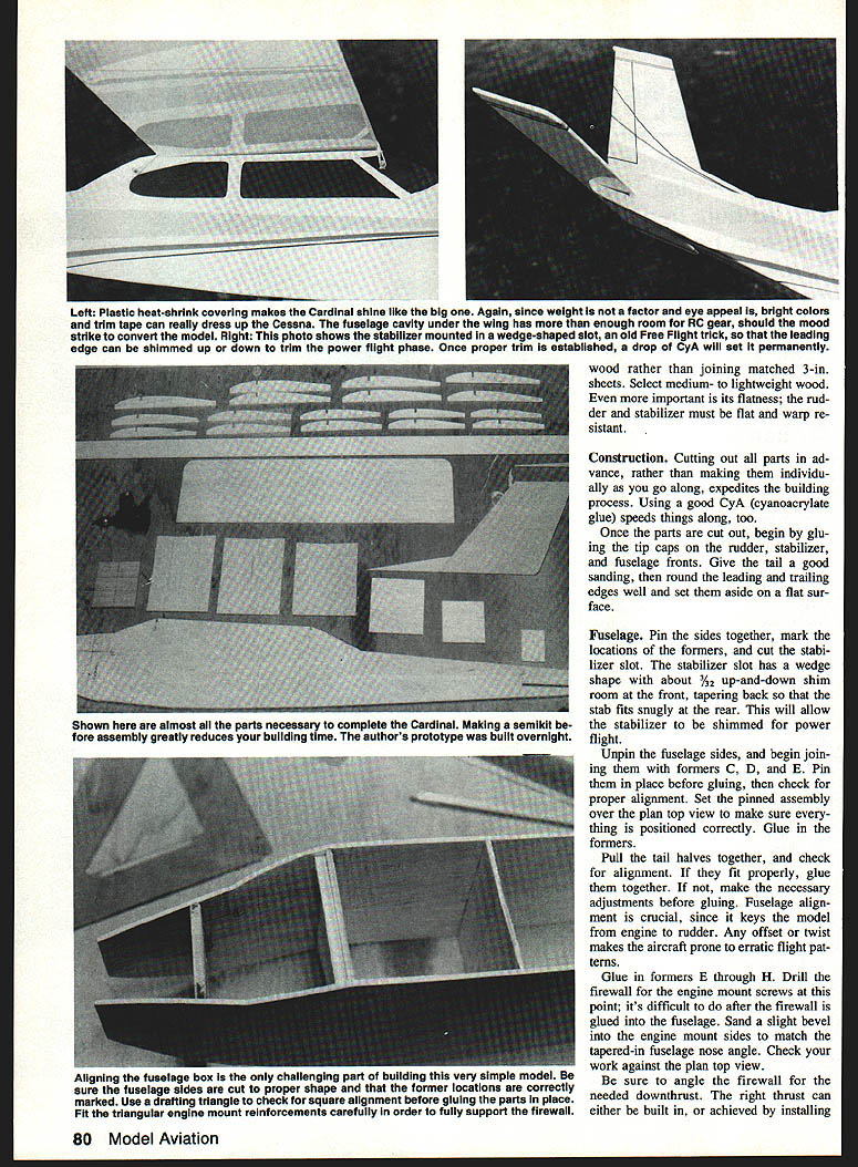
- The stabilizer slot is wedge‑shaped with about 3/32 in. up‑and‑down shim room at the front, tapering back so the stab fits snugly at the rear. This allows the stabilizer to be shimmed for power flight.
- Unpin the sides and join formers C, D, and E. Pin in place before gluing and check alignment over the plan.
- Pull the tail halves together and check alignment. Correct any misfit before gluing—fuselage alignment is crucial.
- Glue in formers E through H. Drill the firewall for the engine‑mount screws now (difficult afterward). Sand a slight bevel on the engine‑mount sides to match the tapered fuselage nose.
- Be sure to set the firewall angle to provide the required downthrust. Right thrust can be built in by angling the firewall or by using small thrust washers behind the engine.
- Fit triangular engine‑mount reinforcements carefully to fully support the firewall—use solid wood rather than joining matched thin sheets.
- Once the firewall‑to‑fuselage joint appears satisfactory, glue it in with slow‑drying wood glue and fit triangle braces and former B.
- Drill and glue the wing hold‑down dowels.
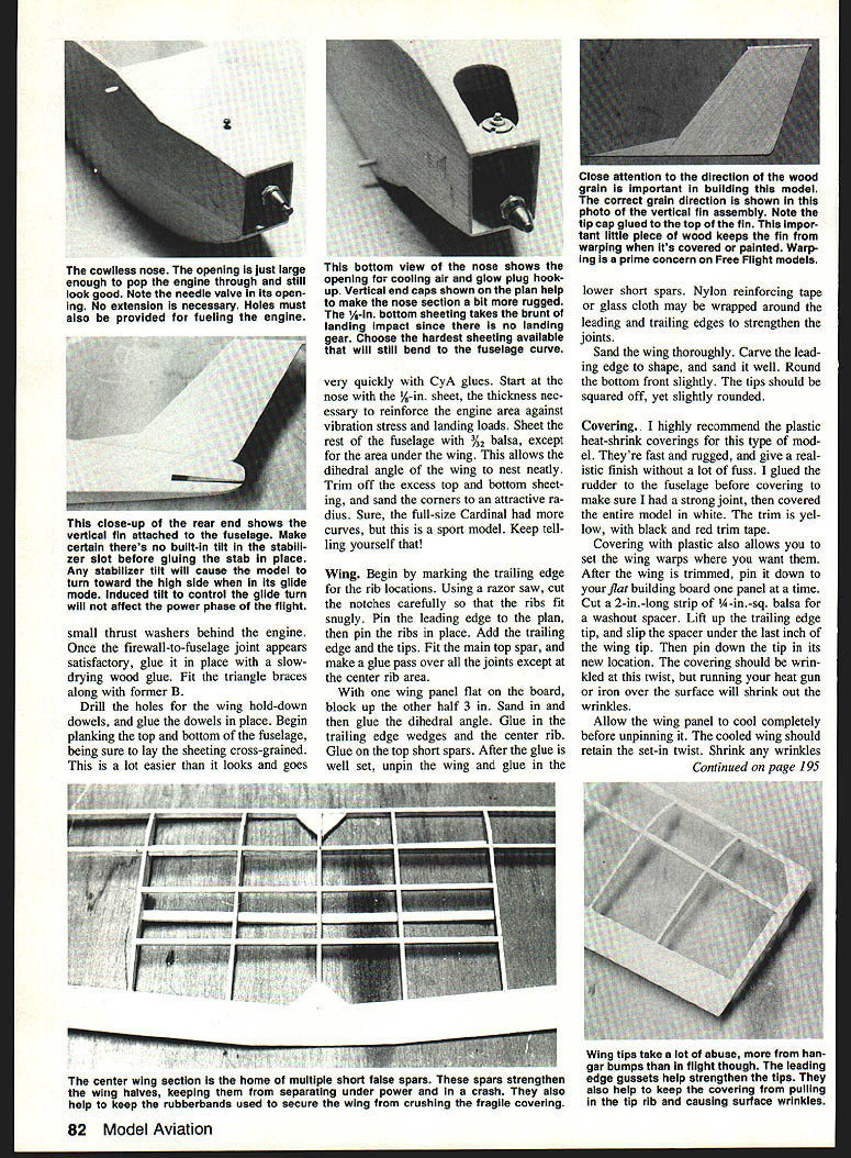
- Begin planking top and bottom of the fuselage, laying sheeting cross‑grained. Start at the nose with 1/8‑in. sheet for engine reinforcement. Use 1/4‑in. bottom sheeting to withstand landing impact (there is no landing gear). Sheet the rest with 3/32‑in. balsa except for the area under the wing to allow the wing dihedral to nest neatly.
- Trim excess sheeting and sand corners to an attractive radius.
Once the fuselage assembly is dry, sand the nose to shape and check alignment again before covering. Balance the model at the CG shown on the plan; add nose weight if necessary. Final trimming for power and glide should be done with small shims at the stabilizer slot; when proper trim is established, a drop of CyA will set it permanently.
Wing
- Mark the trailing edge for rib locations. Cut notches carefully so ribs fit snugly.
- Pin the leading edge to the plan, then pin ribs, trailing edge, and tips in place. Fit the main top spar and glue joints except at the center rib area.
- With one wing panel flat, block up the other half about 3 in. to establish dihedral. Sand and glue the dihedral joint, then glue in trailing edge wedges and the center rib.
- Glue on top short spars. After glue sets, unpin the wing and glue lower short spars.
- Optional: wrap nylon reinforcing tape or glass cloth around the leading and trailing edges to strengthen joints.
- Sand the wing thoroughly. Carve and sand the leading edge, rounding the bottom front slightly. Tips should be squared off but slightly rounded.
Covering
I highly recommend plastic heat‑shrink coverings for this type of model—they're fast, rugged, and give a realistic finish without fuss. I glue the rudder to the fuselage before covering to ensure a strong joint, then cover the entire model in white with yellow trim and black and red trim tape.
Covering with plastic also lets you set wing warps where desired:
- Pin one wing panel at a time flat on the building board.
- Cut a 2‑in. long strip of 1/4‑in.‑sq. balsa for a washout spacer.
- Lift the trailing edge tip, slip the spacer under the last inch of the wing tip, and pin the tip down in its new location. The covering will wrinkle at the twist; shrink the wrinkles with heat.
- Allow the wing panel to cool completely before unpinning. The cooled wing should retain the set‑in twist. Shrink any remaining wrinkles.
Mounting the engine and final assembly
- Cut openings for the cylinder, fuel filler, and needle valve. Fuelproof the engine area with a thin coat of epoxy or several coats of dope.
- Mount the engine and check thrust angles from top and side. Select an 8 x 4 wood propeller and make a bushing for the center hole so it fits properly on the engine shaft.
- Slip the stabilizer into its slot, wedging the leading edge snugly from top and bottom into a neutral position. Glue the trailing edge and pin securely.
- Attach the wing with rubber bands, centering it on the fuselage. Mark the centerline on wing and fuselage so the wing mounts in the same place each time. Small dowel wing keys may be added to the bottom to ensure alignment.
- Fit any remaining fairings and sand smooth.
Trimming and flying
- Balance: Check the balance point and add weight fore or aft until it agrees with the plan CG.
- Power and glide trims should be done separately.
Power trim (climb and turn)
- Climb is adjusted by thrust and incidence. Downthrust compensates for wing lift. If the model zooms and hangs on the prop, add downthrust. If it arcs into the ground, reduce downthrust. If it wants to loop under power, reduce negative incidence in the stabilizer by shimming up the leading edge.
- For a faster climb, add shims to the top of the stabilizer leading edge to increase negative incidence.
- Power turn is trimmed by engine thrust and a rudder trim tab. The model tends to turn left from prop torque; counter this with right thrust and/or rudder tab. Adjust rudder trim slowly—a small change has a large effect.
- Aim for a power turn about 100 ft. in diameter with a gentle climb of roughly 10 ft. per turn.
Glide trim
- Adjust glide independently so it won't interfere with power trim. Test‑glide the model over soft grass.
- If it stalls, add nose weight.
- If it dives, remove nose weight or add tail weight.
- Glide turn is achieved by tilting the stabilizer viewed from front or rear; the model will turn toward the high stabilizer tip. For right circles, raise the right stabilizer tip about 1/4 in. or less.
- The built‑in washout in the wing tips helps keep the wings level; stabilizer tilt upsets that balance enough to allow a turn.
Trimming Free Flight models is an incremental process—adjust a little, test, and repeat.
Final tips and flying routine
- Aligning the fuselage box is critical. Make sure fuselage sides are cut to shape and former locations are correct. Use a drafting triangle to check squareness before gluing.
- Select medium‑weight, lightweight wood and ensure flatness. The rudder and stabilizer must be warp‑resistant.
- I use a small medical syringe to meter fuel into the tank. The Cardinal will fly out of sight on a full tank, so measure your fuel carefully.
- First test flights: limit engine runs to 1–5 seconds, then progressively increase run time as confidence and trim allow.
- On gusty days the Cardinal handles wind well when properly trimmed and with its dihedral. Launch directly into the wind or slightly off to the right.
- Do a ground run after engine installation to check thrust line and vibration; correct as needed.
Sport flying should always be this much fun!
Transcribed from original scans by AI. Minor OCR errors may remain.

