
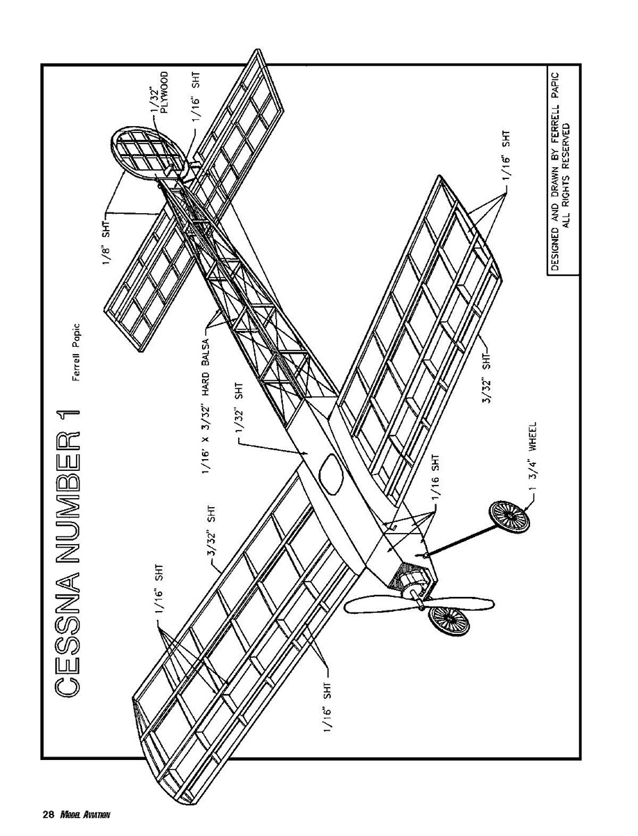
Cessna No. 1
Ferrell Papic
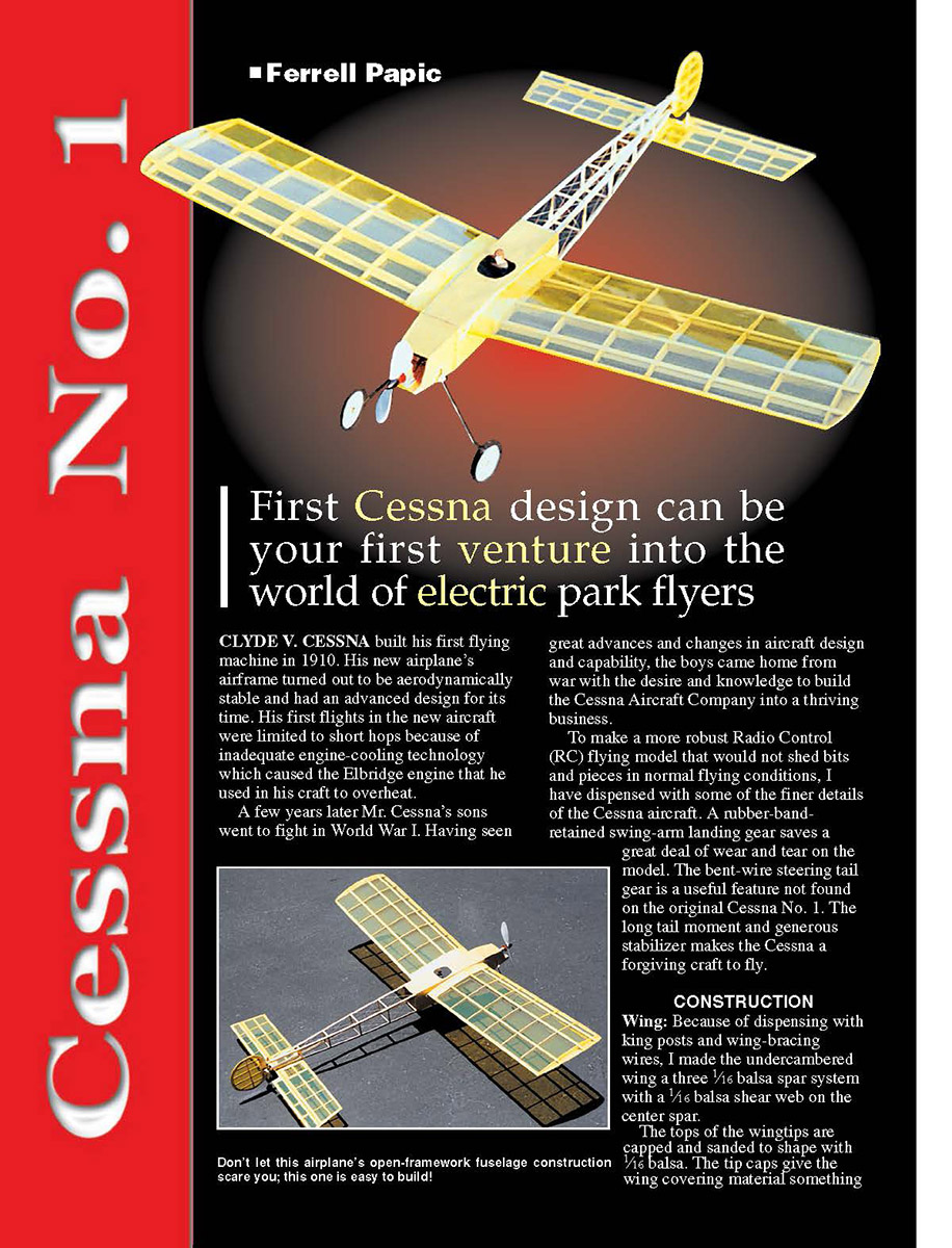
First Cessna design can be your first venture into the world of electric park flyers
Clyde V. Cessna built his first flying machine in 1910. His new airplane’s airframe turned out to be aerodynamically stable and had an advanced design for its time. His first flights in the new aircraft were limited to short hops because of inadequate engine-cooling technology, which caused the Elbridge engine that he used to overheat. A few years later Mr. Cessna’s sons went to fight in World War I. Having seen great advances and changes in aircraft design and capability, the boys came home from war with the desire and knowledge to build the Cessna Aircraft Company into a thriving business.
To make a more robust radio-control (RC) flying model that would not shed bits and pieces in normal flying conditions, I have dispensed with some of the finer details of the Cessna aircraft. A rubber-band-retained swing-arm landing gear saves a great deal of wear and tear on the model. The bent-wire steering tail gear is a useful feature not found on the original Cessna No. 1. The long tail moment and generous stabilizer make the Cessna a forgiving craft to fly.
Construction
Wing
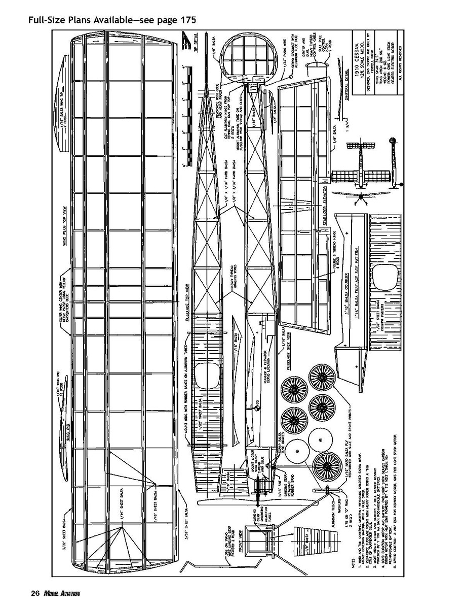
Because I dispensed with king posts and wing-bracing wires, the undercambered wing uses a three 1/16-inch balsa spar system with a 1/16-inch balsa shear web on the center spar. The tops of the wingtips are capped and sanded to shape with 1/16-inch balsa. The tip caps give the wing covering material something to hold on to.
- The wing rib pattern is shown on the plans, with spars and leading and trailing edges for reference.
- The wings are joined with 1 3/4-inch dihedral on each wingtip. This amount of dihedral aids in the tight turns required when flying in an enclosed gymnasium space.
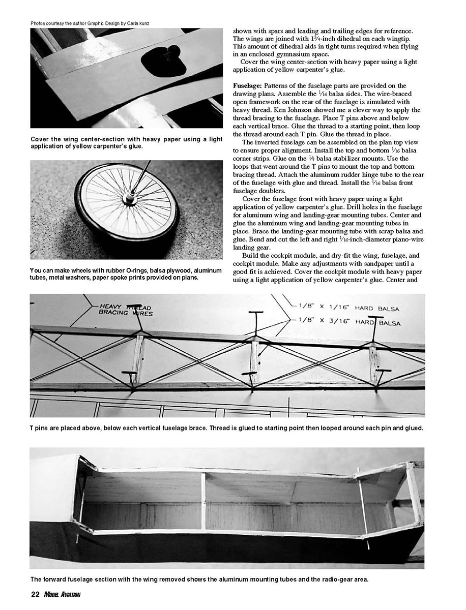
- Cover the wing center section with heavy paper using a light application of yellow carpenter’s glue.
Fuselage
Patterns of the fuselage parts are provided on the drawing plans.
- Assemble the 1/16-inch balsa sides.
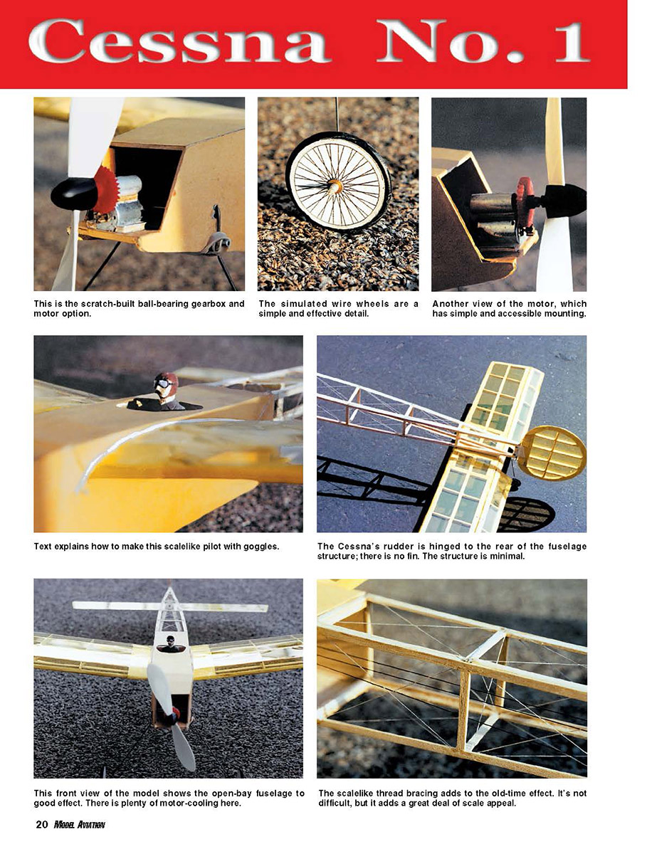
- The wire-braced open framework on the rear of the fuselage is simulated with heavy thread. To apply the thread bracing:
- Place T-pins above and below each vertical brace.
- Glue the thread to a starting point, then loop the thread around each T-pin.
- Glue the thread in place.
- Assemble the inverted fuselage on the plan top view to ensure proper alignment.
- Install the top and bottom 1/16-inch balsa corner strips.
- Glue on the 1/8-inch balsa stabilizer mounts.
- Use the loops that went around the T-pins to mount the top and bottom bracing thread.
- Attach the aluminum rudder hinge tube to the rear of the fuselage with glue and thread.
- Install the 1/16-inch balsa front fuselage doublers.
- Cover the fuselage front with heavy paper using a light application of yellow carpenter’s glue.
- Drill holes in the fuselage for the aluminum wing- and landing-gear-mounting tubes. Center and glue the aluminum tubes in place. Brace the landing-gear mounting tube with scrap balsa and glue.
- Bend and cut the left and right 1/16-inch-diameter piano-wire landing gear.
Build the cockpit module and dry-fit the wing, fuselage, and cockpit module. Make any adjustments with sandpaper until a good fit is achieved. Cover the cockpit module with heavy paper using a light application of yellow carpenter’s glue.
Center and balance the model fore and aft so that the correct center of gravity at the wing main spar is achieved. Use small pieces of lead or other ballast as required.
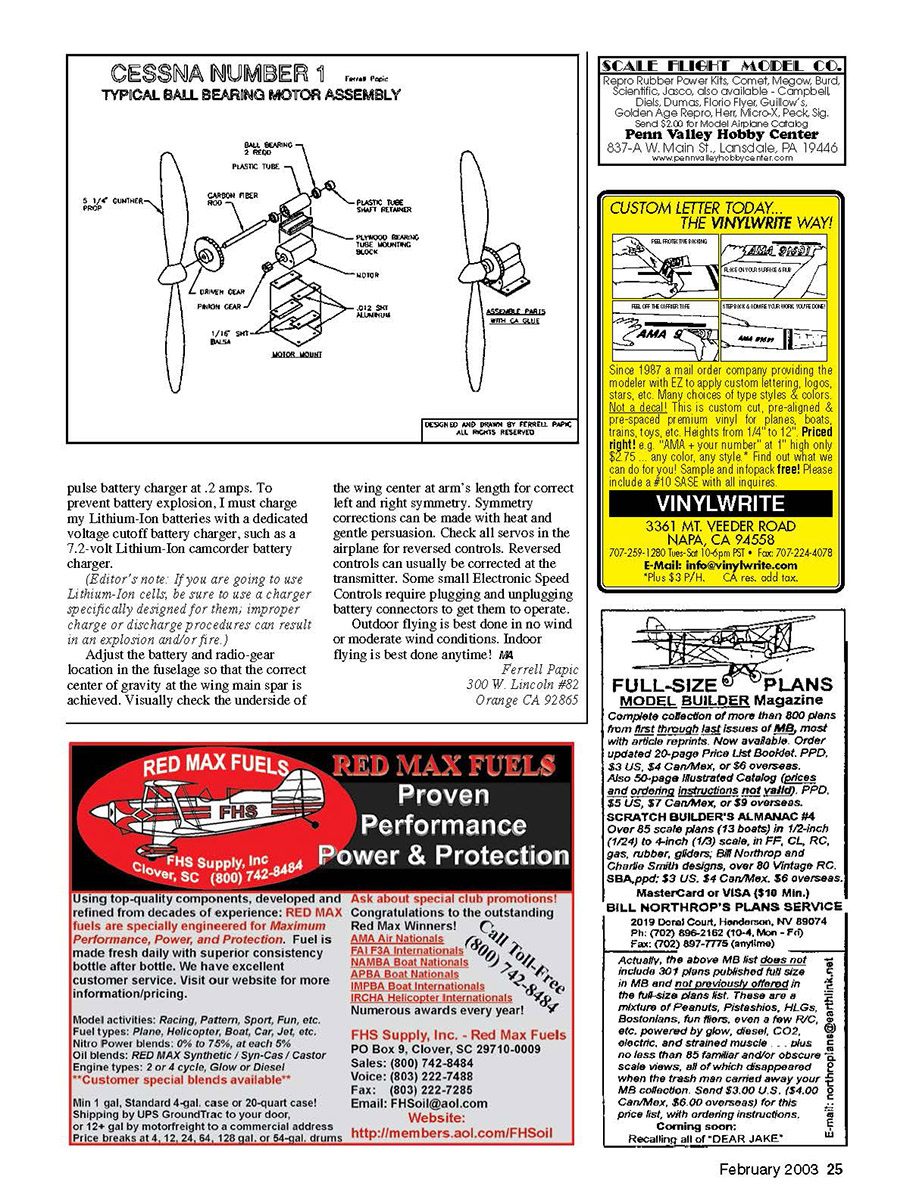
Power and charging
- Use a pulse battery charger at 0.2 amps for general battery maintenance.
- To prevent battery explosion, be sure to charge Lithium‑Ion batteries with a dedicated voltage‑cutoff battery charger, such as a 7.2‑volt Lithium‑Ion camcorder battery charger.
(Editor’s note: If you are going to use Lithium‑Ion cells, be sure to use a charger specifically designed for them; improper charge or discharge procedures can result in an explosion and/or fire.)
Adjust the battery and radio-gear location in the fuselage so that the correct center of gravity at the wing main spar is achieved. Visually check the underside of the wing center at arm’s length for correct left-and-right symmetry. Symmetry corrections can be made with heat and gentle persuasion.
Check all servos in the airplane for reversed controls. Reversed controls can usually be corrected at the transmitter. Some small electronic speed controls require plugging and unplugging battery connectors to get them to operate.
Flying
- Outdoor flying is best done in no wind or moderate wind conditions.
- Indoor flying is best done anytime.
Wheels
You can make wheels with rubber O-rings, balsa plywood, aluminum tubes, metal washers, and paper spoke prints provided on the plans.
Contact
Ferrell Papic 300 W. Lincoln #82 Orange, CA 92865
Credits
Designed and drawn by Ferrell Papic All rights reserved
Transcribed from original scans by AI. Minor OCR errors may remain.

