
Challenger
- Design: Ron Higgs
- Text: Craig and Bill Dunlop
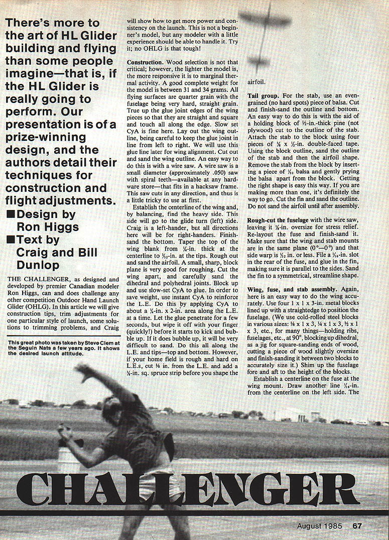
There's more to the art of HL glider building and flying than some people imagine—especially if the HL glider is going to perform. This presentation describes a prize-winning design and details construction and flight adjustments to get more power and consistency on the launch. This is not a beginner's model, but any modeler with a little experience should be able to handle it.
Notes on terminology and handedness
- Craig is a left-hander and describes some of his techniques for left-handed launching. All directional adjustments in this text are given for right-handers unless otherwise noted.
- "CyA" refers to cyanoacrylate (CA) adhesive; both slow-set and instant varieties are mentioned.
Construction
Wood selection and general remarks
- Wood selection is not critical, but the lighter the model the more responsive it is to marginal thermal activity. A good finished weight is 31–34 grams.
- Use quarter-grain for flying surfaces. The fuselage should be straight-grained and fairly hard.
- True up glue-joint edges of wing pieces so they mate squarely and touch along the whole edge. Slow-set CyA is fine for these joints.
- Lay out the wing outline so the glue-joint line runs left-to-right; this line will be used later for wing alignment.
Tools and tips
- A wire saw (.050-in. diameter, spiral teeth in a hacksaw frame) is an easy way to cut outlines; it cuts in any direction and takes some practice.
- A small, sharp block plane is useful for roughing the airfoil.
- Cold-rolled steel blocks in various sizes (1 x 3, 1 x 3/4, 1 x 1/2, 1 x 1/4 in.) are useful jigs for holding and aligning parts.
Wing
- Cut out and sand the wing outline after laying it out.
- Establish the centerline of the wing and balance it to find the heavy side; the heavy side will be oriented to the glide-turn side (left for Craig). Right-handers should reverse directions.
- Finish-sand the bottom of the wing. Taper the top of the wing blank from 1/4 in. thick at the centerline to 3/32 in. at the tips.
- Rough out and sand the airfoil, then cut the wing apart and carefully sand the dihedral and polyhedral joints.
- Block up and glue panels with slow-set CyA to save weight.
- To harden the leading edge without adding much weight, apply instant CyA to about a 1/4-in. x 2-in. area along the leading edge at a time. Let the glue penetrate briefly, then wipe off quickly before it kicks and bubbles. If your field is rough on L.E.s, route 1/16 in. off the L.E. and add a 1/16-in. square spruce strip before shaping.
Tail group (stab and fin)
- Use an even-grained (no hard spots) piece of balsa for the stab.
- A recommended method: attach the blank to a 1/2-in.-thick pine holding block cut to the stab outline with four pieces of 1/8 x 1/8-in. double-faced tape. Block and sand the outline and airfoil shape against the block, then remove the stab by inserting a piece of 1/32-in. balsa and gently prying apart.
- Cut and sand the fin outline. Do not sand the fin airfoil shape until after assembly.
- When installing the fin, file a 1/8-in. slot in the rear of the fuselage and glue the fin in so it is parallel to the fuselage sides. Sand the fin to a symmetrical, streamlined shape.
Fuselage
- Rough-cut the fuselage with the wire saw, leaving about 1/8 in. oversize for stress relief. Re-layout and finish-sand to final dimensions.
- Make sure the wing and stab mounts are in the same plane (0°/0°) and that side warp is 1/8 in. or less (some instructions note 1/32 in. tolerances at the rear—keep side warp minimal).
- Sand the stab mounting area on the fuselage and check that the stab tilt is about one-half the angle of the main wing panel; maintain the 0°/0° relationship between wing high side and stab.
Wing, fuse, and stab assembly
- Accurately position the fuselage between four 1 x 3-in. metal blocks lined up with a straightedge when assembling the wing.
- Establish a wing centerline on the fuselage at the wing mount and draw another line 1/16 in. to the left for the fore-aft offset.
- Put a straight pin on the fuselage centerline at the front of the fin and file a small V-notch on its tip; use this pin (not string) for wing alignment.
- Rig up blocks for the polyhedral breaks. If the wing mounting surface is 1 in. high, blocks will be 1-1/16 in. so there are three contact points.
- Use white glue for the wing-to-fuse joint to allow time for accurate location. Use notched wood to line up the wing glue-joint line left-to-right and let dry.
- Cut out the finger rest noting grain direction; a good fit is required. Streamline and bond the finger rest area with white glue and then slow-set CyA.
- Mix a small batch of 5-minute epoxy and form small fillets around the finger rest on both sides of the fuse; wet your finger and smooth the fillets. These fillets significantly increase strength and help prevent wing separation.
- Line up the stab centerline and glue with CyA (or appropriate adhesive). If the wing high side is on the left, the stab will need a corresponding left tilt.
Wash-in tab and finishing
- Glue a 1/32-in. washin tab on the wing. Sand away about half of its thickness and fair it into the wing surface.
- Fill grain and apply three coats of 50% nitrate dope, sanding between coats, to attain a smooth finish.
- Use fluorescent paint on the wing tips and fin for good visibility.
- Before the final coat of dope on the stab and fin, apply lightweight Japanese tissue:
- Apply a strip of tissue to the rear half of both sides of the fin.
- Apply a 1/4-in.-wide strip to the rear of the stab—top only on the left and bottom only on the right.
- Bond the tissue with thinned dope. These tissueed surfaces make later flying-trim adjustments easier.
- Add sandpaper grips as desired.
Trimming, Balancing, and Launching
Balancing (C.G.)
- Balance the finished model at the recommended center of gravity: on the bottom of the wing about 1/4 in. from the fuselage. Make a small pencil indent on both sides to mark the points.
- Hold two pencils upright in one hand so the model rests on the indents and add lead to the nose until the model balances. This method is accurate and helps produce a model that will "fly off the board."
D.T. and other release devices
- The authors use a swinging weight for D.T. (dead stick) and are experimenting with a pop-out spin tab.
- A pop-up stab is not recommended because of the long moment arm and the small fuselage cross section (would require beefing up the fuselage and moving weight forward).
- Adding rear weight requires significantly more nose lead and is not efficient.
Preflight setup and bending adjustments
- Slightly bend the fin left (about 1/64 in.). Do not wet or steam; simply compress the wood on the inside of the bend while stretching the outside—tissue support prevents splitting.
- Bend the left rear of the stab down slightly and bend the right rear of the stab up slightly more than the left was bent down. This contributes to the desired flick rollout.
- These small wood bends are stable until re-bent.
Initial hand-glide and part-power checks
- You may hand-glide, but the recommended procedure is controlled launches at increasing power levels:
- Throw at a little more than half power with a slightly exaggerated bank to get the model up in an initial launch attitude of about 60°–70°. If it stalls in the glide, add a little clay to the nose.
- If it dives, bend the right side of the stab up a little more.
- If the model sweeps over on its back on launch, there is too much up on the right side (or not enough down on the left); reduce right-up or increase left-down.
- Repeat throws and small adjustments until the model climbs almost straight up. If there is not enough left rudder, the model will go too far right and have a wide glide circle. The model should go slightly right on launch for proper transition.
Increasing power and final launch trims
- Try about 3/4 power at 70°–75°. At this speed washin in the left main panel begins to take effect. Too much washin will lift the wing on launch and make transition difficult and increase the glide circle.
- Keep adjusting the stab and rudder to control the launch, and add or remove clay/lead to control the glide. Don't over-trim on part-power launches.
- Full-power launches should be at about 75°–80°:
- If launched too near vertical the model can come over backwards with poor transition.
- If the model loops or sweeps back near the top, there is too much up-bend—reduce up-bend and/or reduce power slightly until it transitions smoothly with a slight flick-out.
- If the model still goes over backwards at full power, reduce the left bend in the fin slightly or add a small amount of right thrust.
- If the model stalls at the top, add a small amount of down-thrust or increase stab tilt back.
Fine trimming for glide circle and conditions
- If the model transitions shakily and loses altitude before settling into its glide, try any of these small adjustments:
- Bend the right stab up a very small amount.
- Decrease down-bend in the left stab slightly.
- Remove a small amount from the washin tab.
- Reduce the left rudder bend slightly.
- Once the launch and transition are correct, adjust for the glide circle. You may need to remove and re-position the stab for larger changes: more stab tilt tightens the glide turn; less tilt opens it.
- Air density varies with time of day, location, and altitude. Do final trimming in the middle of the day; only minor adjustments are usually needed at other times.
Launch technique (Craig's comments)
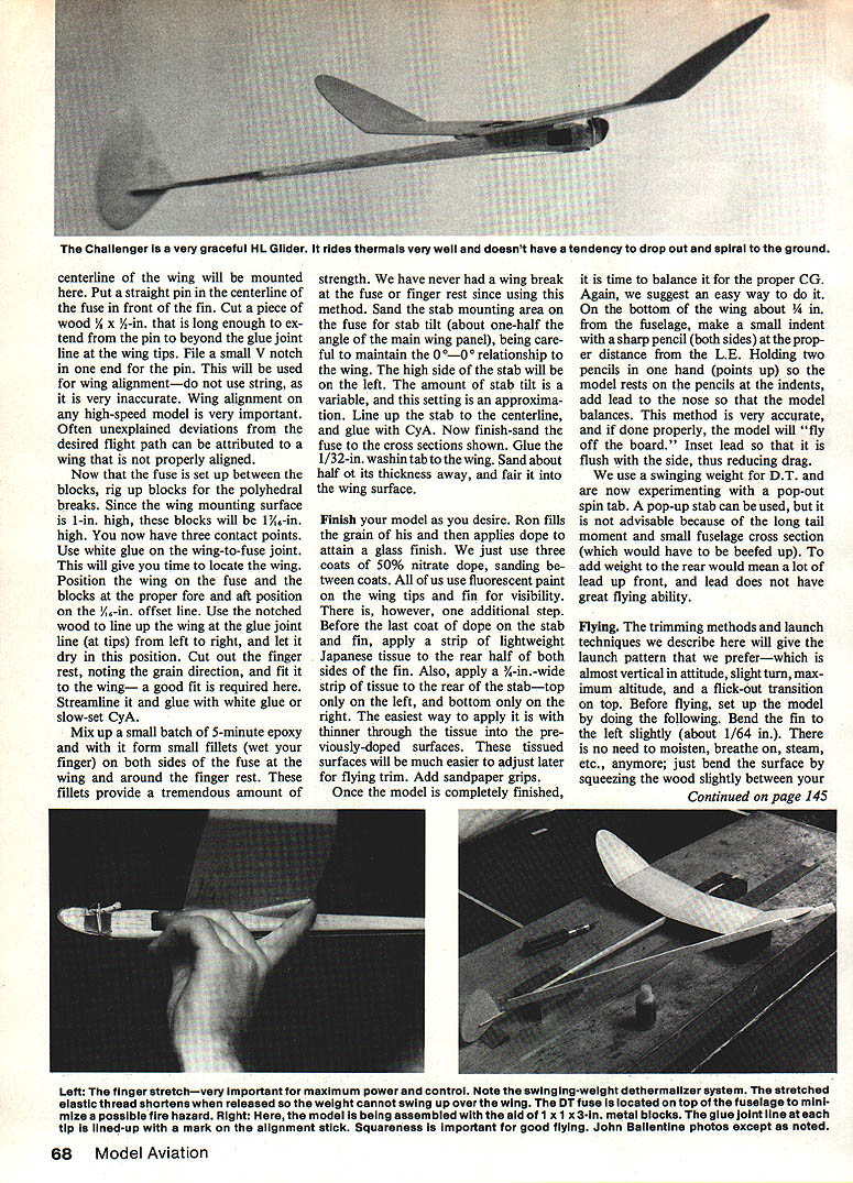
- For maximum power, stretch the fingers from the finger rest to the sandpaper grips with a strong follow-through. The stretch and follow-through add a snap at release and produce more power.
- Warm up the arm before hard launches: shoulder rotations, mock throws, and throwing a ball help. Throwing OHLGs is hard on the arm—stop if it hurts.
- The preferred launch is almost vertical (about 75°–80°) with a slight tilt to the left and an almost overhand motion. A 10–15 ft run followed by a very hard throw is recommended (Craig describes his left-handed launch).
Finding lift
- Long-duration flights require help from the air. Piggybacking and bubbles can be useful but are not always reliable.
- Mylar streamers on a long pole can indicate local lift. The authors have experimented with a helium-filled weather balloon with an attached Mylar streamer raised to launch altitude; this can show what the air is doing where the model will fly and looks promising.
Transcribed from original scans by AI. Minor OCR errors may remain.

