
The Chambermaid
By Bill Henn
Background: Raceplane Rules and Events
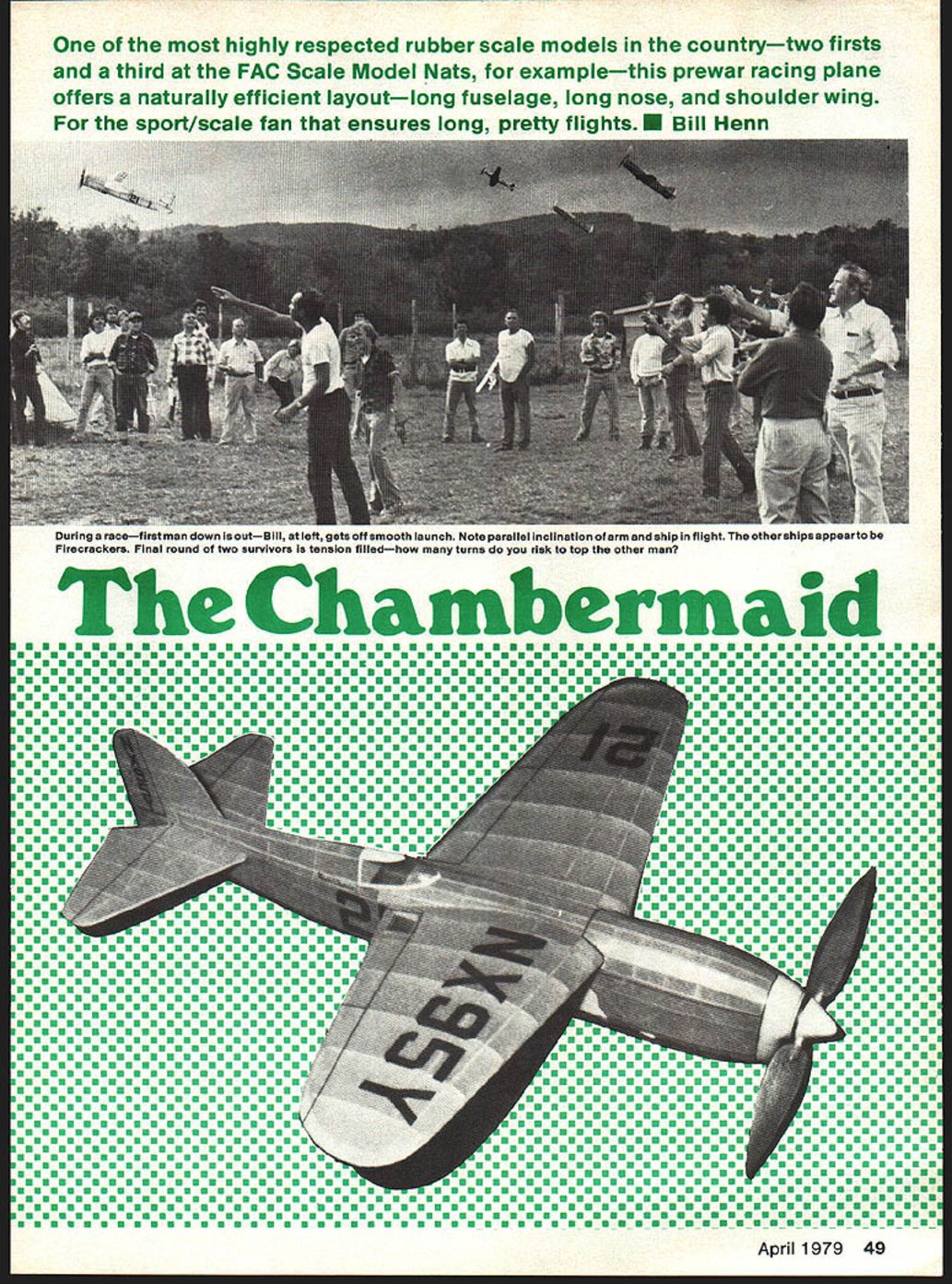
The Connecticut Flying Aces Club (originators of the P‑Nut Scale) can also be credited with starting a raceplane movement that has grown in popularity. Raceplane events are divided into three categories: the Shell Speed Dash, the Greve, and the Thompson Trophy Races. The Shell Race is strictly an endurance event. Models competing in the Greve and Thompson are mass launched and fly against each other instead of against a stopwatch. Repeated heats are flown with the first model down eliminated each time until only the winner remains.
There is no static scoring, but models must be reasonably accurate replicas of actual aircraft that were flown in, or designed for, the pre‑WWII Thompson or Greve races. High‑wing monoplanes are not allowed and wingspan is limited to 24 inches. Models of racers that had retractable landing gear may be built with wheels in the retracted position. A complete set of rules for these raceplane events appeared in the March 1977 issue of Model Builder magazine.
Choosing a Design
My interest in this scale category began in early 1976. Since high‑wing planes were excluded, a shoulder‑wing design with a low thrust line seemed promising. Mr. Smoothie, an obscure racer designed for the 1938 Thompson Trophy Race, fit the bill. I obtained plans for a 24‑in. Smoothie from Art Hall (P.O. Box 485, Winter Park, Florida 32789) and finished the model for the fall FAC meet. Although the first Smoothie was rather heavy, it placed third in the Shell and second in the Thompson. It was stable under power, capable of flights over a minute, and had excellent glide characteristics.
A second simplified 24‑in. Smoothie built the following winter was nearly 1/2 ounce lighter and routinely flew 85–90 seconds. Dissatisfaction with the Smoothie’s small wing area led me to seek a better subject.
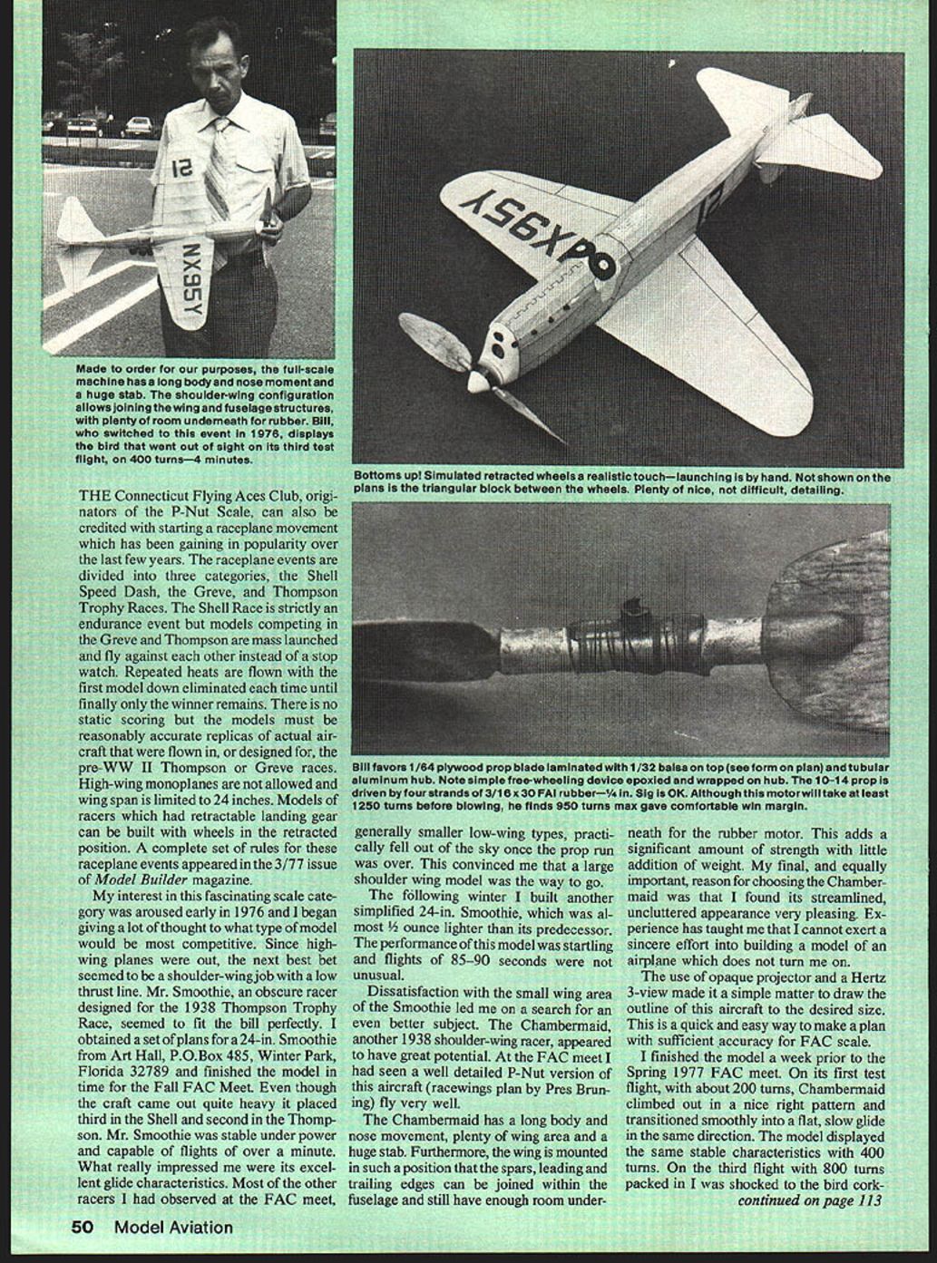
The Chambermaid, another 1938 shoulder‑wing racer, appeared to have great potential. I had seen a well‑detailed P‑Nut version fly very well at the FAC meet. The Chambermaid has a long body and nose moment, plenty of wing area, and a large stabilizer. The wing is mounted so that the spars, leading edge, and trailing edge can be joined within the fuselage and still leave enough room underneath for the rubber motor—adding strength with little weight penalty. Finally, I admired its streamlined, uncluttered appearance; I’ve learned I must be excited by a subject to put sincere effort into building it.
I used an opaque projector and a Hertz 3‑view to draw the outline to size—a quick, easy way to make a plan with sufficient accuracy for FAC scale.
Flight Results and Contest Record
I finished the Chambermaid a week prior to the Spring 1977 FAC meet. On its first test flight, with about 200 turns, Chambermaid climbed in a nice right pattern and transitioned smoothly into a slow, flat glide. It remained stable with 400 turns. On the third flight, with 800 turns, I was shocked to see the bird cork‑screw up like a Wakefield and fly out of sight (OOS) in about four minutes. By some miracle, about an hour later I retrieved the model approximately a mile downwind. It had flown over a small forest, several communities, and landed in the only open area in the vicinity. It was grounded until the contest, where it easily won the Shell and Greve Races and placed third in Scale.
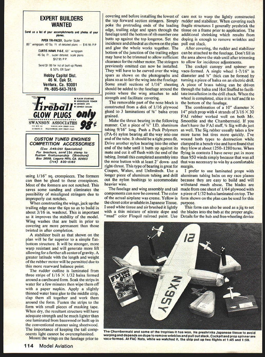
During the morning of that meet, in still damp air, two flights were clocked at about 1:45 and another at 1:59. The model wasn’t flown again for a year until the Spring 1978 FAC meet where it again won the Shell and Greve Races. At the July 1978 FAC Nats in Johnsville, PA, a 15‑minute thermal flight earned Chambermaid second place in Scale. The next day it was nudged out of first place in the Shell by my own Mr. Smoothie, which caught some good air and maxed. I used Smoothie instead of Chambermaid in the Thompson race—my son Billy convinced me—and Smoothie flew beyond the field into a tree and was disqualified.
Chambermaid later won the Shell and Greve Races (during a rainstorm) at the October 1978 FAC bash. Competition at the Connecticut meets is some of the toughest; winning any rubber free‑flight event in Yankee territory is never easy.
Construction Overview
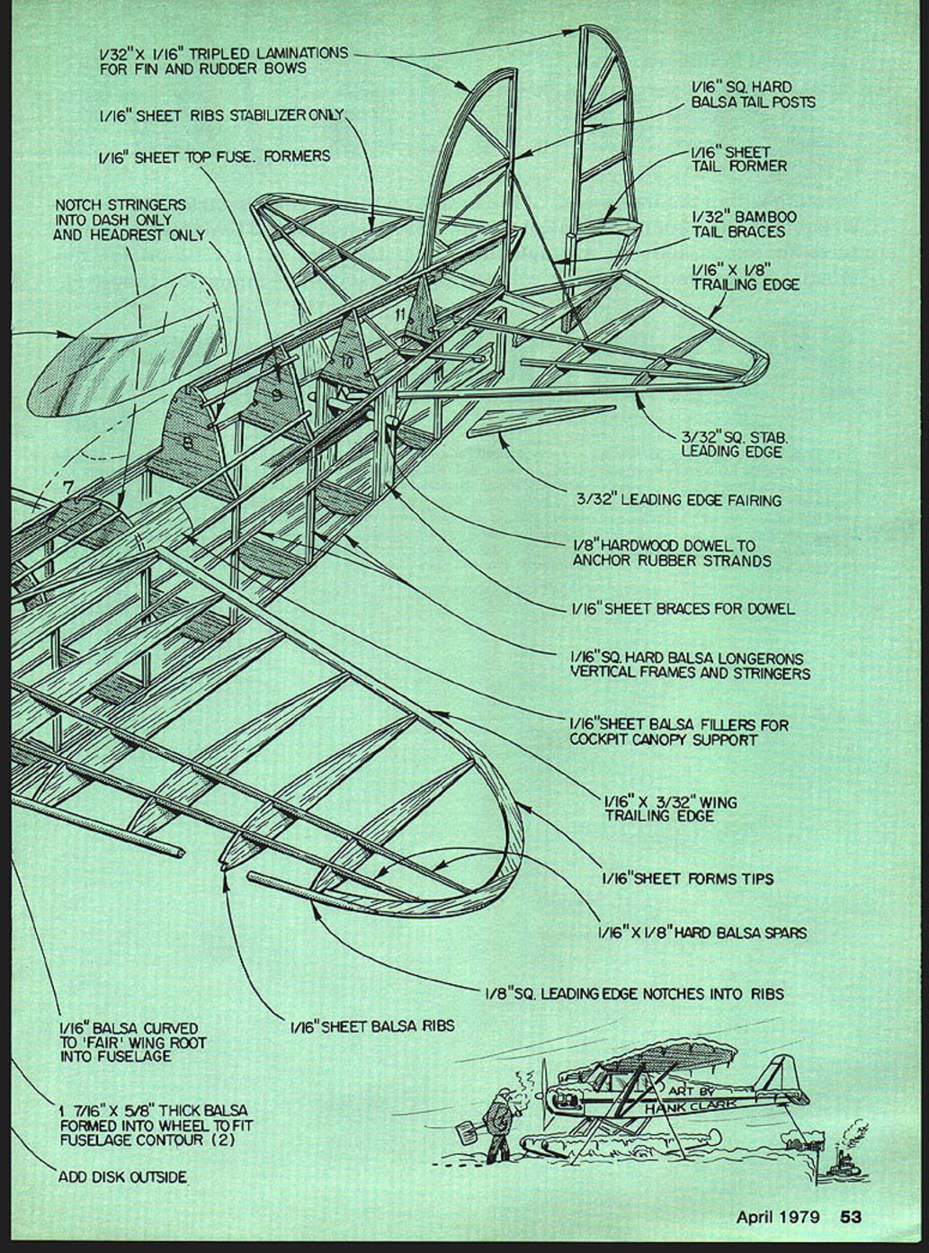
Construction is straightforward with no unusual difficulties. Choice of wood is paramount: use the lightest contest balsa available for fuselage formers, nose block, wing ribs, wingtips, and the rudder and stabilizer parts. Use slightly firmer wood for other components, except the fuselage longerons, which should be hard balsa.
The fuselage has flat sides for easy assembly. Join the sides in a box‑like fashion using 1/16" sq. crosspieces; then glue the formers to these crosspieces. Most formers are not notched—this saves sanding and avoids misaligned stringers caused by improperly cut notches.
Wings
When constructing the wings, jack up the trailing edge near the tips to build in about 3/16" washout. This improves stability. Built‑in washout prior to covering is more permanent than twisting in washout after completion.
Use 1/16" sheet ribs, 1/8" sq. leading edge (notched into ribs), 1/16" x 1/8" hard balsa spars, 1/16" x 3/32" trailing edge, and 1/16" sheet tips and fillers as shown on the plan. Notch stringers into the dash and headrest only. Add small 1/16" sheeting sections around the wing attachment points for strength and easier covering.
Stabilizer and Rudder
Build the stabilizer as shown on the plan (a boxed or built‑up section) rather than a simple flat‑bottom structure. It will be stronger, more warp resistant, and generate more lift, permitting a further aft center of gravity and more rubber motor length/weight options.
The rudder outline is laminated from three strips of 1/16" x 1/32" balsa formed around a cardboard form. Soak the strips briefly in water, wipe them dry, apply slightly thinned water‑based glue to the middle strip, sandwich them together, and work them around the form. Fasten to the form with small pieces of masking tape. When dry, the laminated rudder will have adequate strength and be much lighter than basswood or conventional built‑up sheetwood. Keeping tail components light is critical.
Mount the wings on the fuselage prior to covering and before installing the lowest top forward stringer. Poke the protruding ends of the leading edge, trailing edge, and spars through the fuselage until the bottom of rib number one butts against the top longeron. Set incidence and dihedral as shown and glue everything together. The bottom junction of the trailing edges may need trimming for rubber motor clearance. Then install the previously omitted stringers, curving them over the wing spars to fair the wing into the fuselage.
Nose Block and Thrust Bearing
The removable part of the nose block is constructed from a disk of 1/16" plywood glued to three laminations of 1/8" balsa cross‑grained.
Make the thrust bearing as follows: cut a piece of 1/4" I.D. aluminum tubing 9/16" long. Press a Peck Polymers (PA‑6) nylon bearing into one end until tight. Drive another nylon bearing into the other end until it butts the first, and cut it flush with the end of the tubing. Install this assembly into the nose button with at least 2° down and right thrust. This bearing style is great for Coupes, Wakes, and Unlimiteds. For heavier wire use a longer piece of aluminum tubing and drill out the nylon bushings.
Canopy, Spinner, and Wheel
The cockpit canopy and spinner are vacu‑formed. A single wheel (1‑7/16" diameter x 5/8" thick) can be turned from balsa on an electric drill. Drive a brass tube through the balsa and hot‑stuff it to fit the drill chuck. When completed, slice the wheel in half and fit the halves to the fuselage bottom.
Covering and Finish
Cover the fuselage, wing assembly, and tail components after assembly. The actual airplane color was crème; yellow is the closest available Japanese tissue. I used white tissue and airbrushed it lightly with a thin mixture of nitrate dope and “mud” color Floquil railroad paint. Take care not to warp the lightly constructed rudder and stabilizer—preshrink the tissue on a frame prior to application. The doping will remove wrinkles and pull out slack.
Attach the rudder and stabilizer after covering. Don’t fill the area above the stabilizer until after trimming to allow incidence adjustments.
Propeller, Rubber Motor, and Hub
A 10" diameter x 14" pitch prop combined with four strands of 3/16" x 30" FAI rubber worked well on both Mr. Smoothie and the Chambermaid. If you don’t have FAI rubber, 3/16" Sig will do; it usually takes a few more turns but tires more quickly. Both types blow at about 1250–1280 turns when wound to destruction in a vise. In contests I never needed more than 950 winds.
I prefer laminated props with aluminum tubing hubs because they’re easy to build and durable. Blade construction: one sheet of 1/64" plywood with a piece of 1/32" balsa laminated on top. Use the form on the plan as a jig to set blade angle into the hub. Details for the hub and free‑wheeling device are on the plan; if carefully constructed, the free wheeler is rugged and dependable.
A longer motor (36–40") made from four strands of braided 1/4" FAI rubber can help if the model is heavy. Braiding reduces weight shift when long motors bunch up. After braiding, a 40" motor will measure less than 36"; it will take about 1500 turns and keep a 10/14 prop spinning well for over a minute. I never used such a motor in Chambermaid but did in other models with good results.
Trimming and Flying
This model is extremely easy to trim; typically only minor adjustments are necessary.
- Prior to installing the motor and prop, balance the model at the point shown on the plan by adding clay to the nose.
- Test‑glide the model and adjust stab and rudder to obtain a floating glide with a slight right turn. Avoid too tight a glide turn to prevent spiraling under power.
- Remove the clay, install the prop and rubber motor, wind the slack out of the motor, and rebalance at the same point. If balanced well, no extra weight should be necessary. My model weighed 67 grams all up with a 14.5‑gram motor.
- Crank in about 200 turns and make a test heave. The model should climb gently to the right. If it doesn’t turn, shim the nose plug to add right thrust. Correct minor stalling or diving tendencies with thrust adjustments rather than changing rudder/elevator settings.
- Increase turns gradually with each successive flight. Properly adjusted, the model will climb very high and glide well even with the large free‑wheeling prop.
If your model is much lighter than mine, equip it with a D.T. and use it for Category III Unlimited. If heavier, consider more rubber or a longer braided motor.
Launching Tips and Pylon Notes
Two common launch problems are torque reaction to the left and the engine leaning out or quitting on a hard launch. A hard javelin‑type launch helps overcome torque reaction, while a soft launch eases the leaning‑out problem. Experimentation with air pickup position and tank height usually helps solve these issues. Dropping the nose just prior to launch can help the engine load up, allowing a hard throw without quitting.
We have operated largely within the AMA 1978–79 Provisional Rules for 1/2A Pylon and have found this keeps the event accessible. Keep events inexpensive and easily constructed so the average modeler can compete. If specialists are allowed to refine events around their capabilities, participation by average modelers will dwindle.
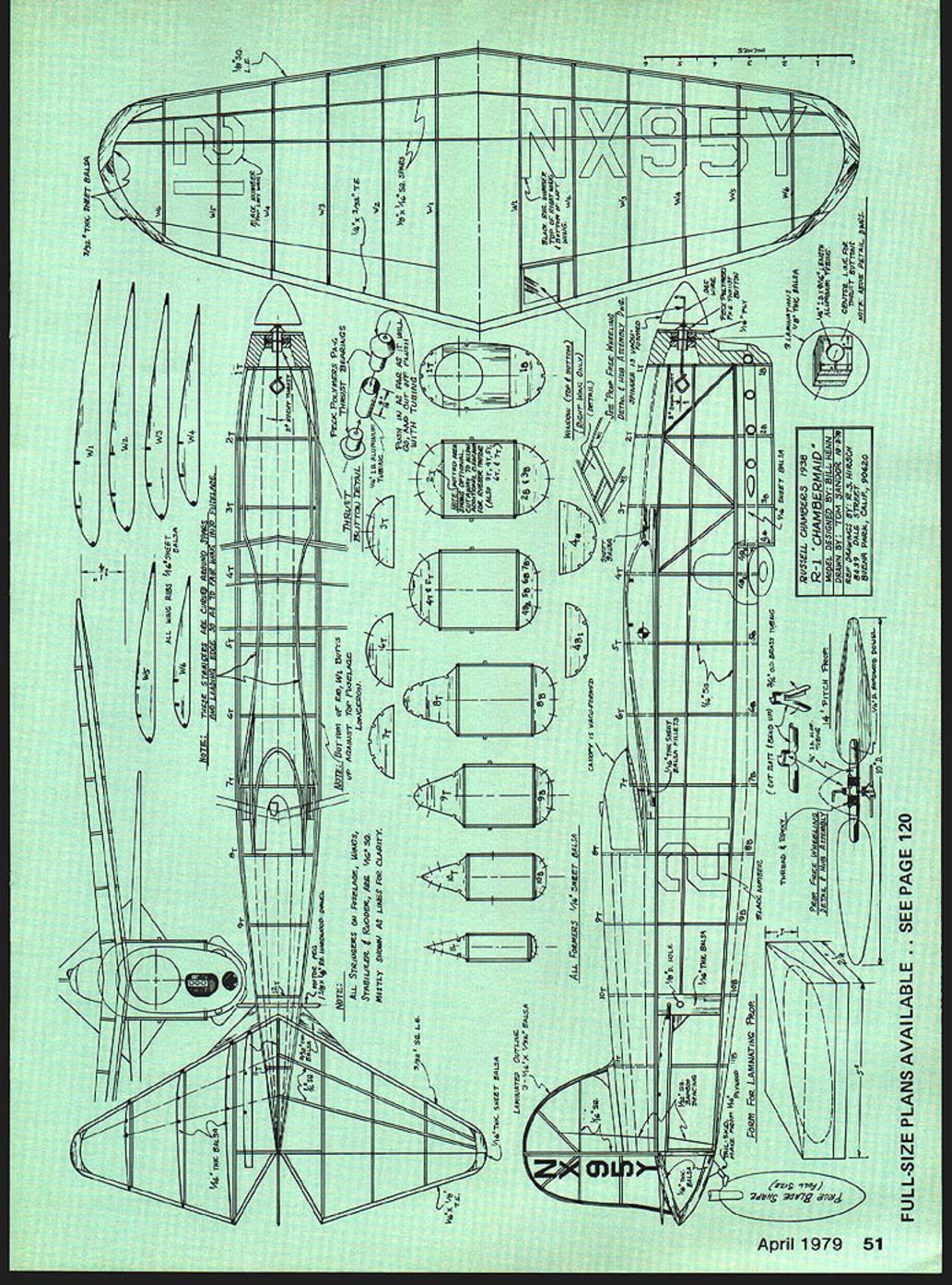
Plan and Parts (notes from the plan)
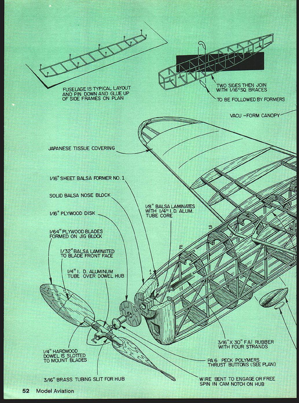
- Fuselage is typical layout; pin down and glue up side frames on plan.
- Two sides then join with 1/16" sq. braces, followed by formers.
- Vacu‑form canopy.
- Japanese tissue covering.
- 1/16" sheet balsa former No. 1.
- Solid balsa nose block.
- 1/16" plywood disk.
- 1/64" plywood blades formed on jig block.
- 1/32" balsa laminated to blade front face.
- 1/4" I.D. aluminum tube over dowel hub.
- 1/8" balsa laminates with 1/4" I.D. aluminum tube core.
- 1/4" hardwood dowel slotted to mount blades.
- 3/16" brass tubing slit for hub.
- 3/16" x 30" FAI rubber with four strands.
- PA‑6 Peck Polymers thrust buttons (see plan).
- Wire bent to engage or free spin in cam notch on hub.
- 1/32" x 1/16" tripled laminations for fin and rudder bows.
- 1/16" sheet ribs (stabilizer only).
- 1/16" sheet top fuselage formers.
- Notch stringers into dash only and headrest only.
- 1/16" balsa curved to fair wing root into fuselage.
- 1/16" sheet balsa ribs.
- 1/8" sq. leading edge notches into ribs.
- 1/16" x 1/8" hard balsa spars.
- 1/16" sheet forms tips.
- 1/16" x 3/32" wing trailing edge.
- 1/16" sheet balsa fillers for cockpit canopy support.
- 1/16" sq. hard balsa longerons, vertical frames and stringers.
- 1/16" sheet braces for dowel.
- 1/8" hardwood dowel to anchor rubber strands.
- 3/32" leading edge fairing.
- 3/32" sq. stab leading edge.
- 1/16" x 1/8" trailing edge.
- 1/32" bamboo tail braces.
- 1/16" sheet tail former.
- 1/16" sq. hard balsa tail posts.
- 1‑7/16" x 5/8" thick balsa wheel formed to fit fuselage contour (2; add disk outside).
- Art by Hank Clark.
Closing
This is an extremely rewarding, easy model to trim and fly. I would be pleased to hear from anyone who builds the model.
My address: 53 Hall St. Clifton, NJ 07014.
Transcribed from original scans by AI. Minor OCR errors may remain.

