
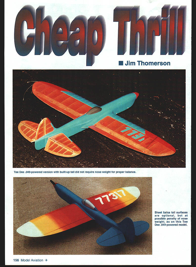
Cheap Thrill
Jim Thomerson
I've enjoyed designing and building small Control Line Stunt airplanes since the days of the Atwood Wasp .049. Designs have gradually grown from 24" to 36" in wingspan and from six to seven ounces up to 11–13 ounces in weight. From time to time a model has been powered by an .074 or an .09.
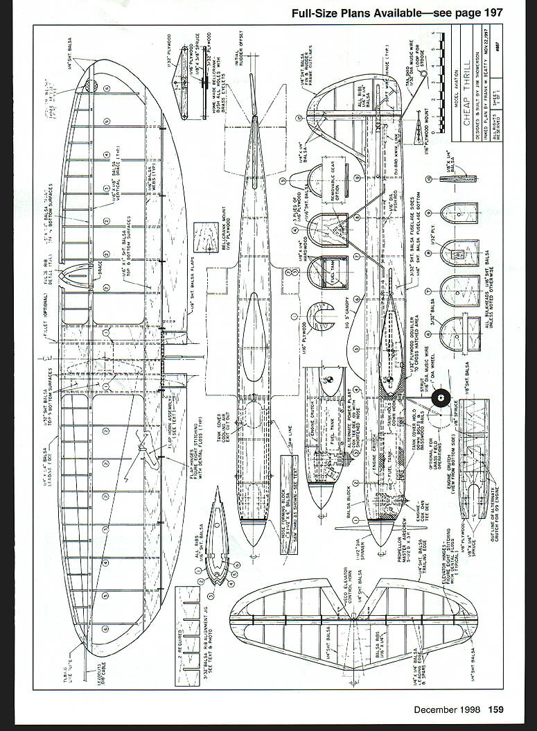
Today there are a number of high-quality small engines, diesel and glow, in the .049 to .10 size range. You are encouraged to try your favorite engine in a Cheap Thrill. The plans show front-end modifications for the Tee Dee .09.
I fly Stunt competitively at the PAMPA (Precision Aerobatics Model Pilots Association) Advanced level. My goal is to maintain and increase competence so I can conduct flying sessions without mishap and fly well enough for all present to enjoy them. The Cheap Thrill flies the pattern very well, with a surprisingly solid feel. My 1/2A models have handled wind better than some larger Stunt airplanes, and sometimes fly when everything else stays in the van.
The 1/2As and their slightly bigger siblings are great fun to build and fly.
CONSTRUCTION
Stabilizer and Elevator
Built-up construction is recommended for the 1/2A. I have also used very light 1/16" sheet with good results. The control horn shown is the small Veco unit.
- Sand the stabilizer and elevator to shape.
- Using thin cyanoacrylate (CyA) glue, cover the center of the stabilizer with a two-inch-wide piece of lightweight glass cloth (not necessary on a built-up stab).
- Apply a couple of coats of clear dope and sand with 400-grit sandpaper until smooth.
- Cover with tissue, then continue clear-doping, sanding between coats with 600-grit paper to remove fuzzies until uniformly shiny.
- Set aside until later.
The elevator horn installation uses the small Veco unit; hinge the stab and elevator after preparing the pushrod and linkages (see fuselage section).
Wing
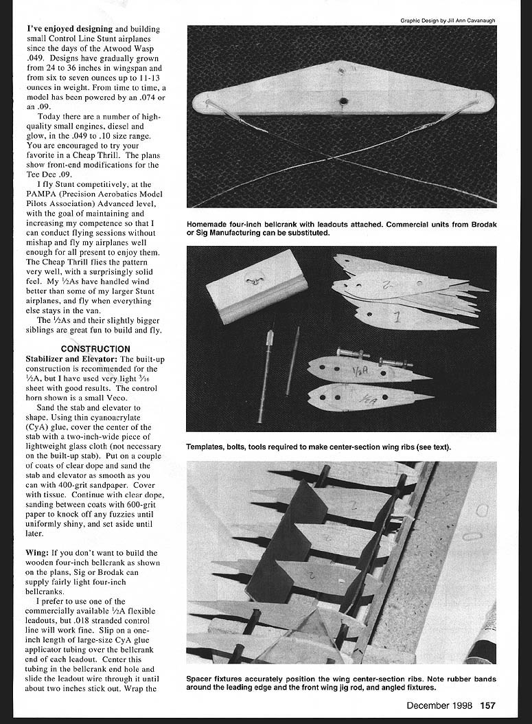
If you don't want to build the wooden four-inch bellcrank as shown on the plans, Sig or Brodak can supply fairly light four-inch bellcranks. I prefer commercially available 1/2A flexible leadouts, but .018" stranded control line will work fine.
Leadouts
- Slip a one-inch length of large-size CyA glue-applicator tubing over the bellcrank end of each leadout. Center the tubing in the bellcrank end hole and slide the leadout wire through until about two inches stick out.
- Wrap the leadout with fine beading wire (available at craft stores) and wrap smoothly so it won't hang up in the fuselage or bellcrank.
- Leave the outer ends unfinished for now. Note: one leadout will be about four inches longer than the other when finished to ensure line connectors don't snag.
- When the wrap is finished, rub on Sig-Ment to help hold the wire and smooth the surface.
Rib and center-section preparation
- Make templates for the center-section ribs from plywood or aluminum.
- Stack 14 pieces of light quarter-grain 1/16" balsa between the templates to assemble the wing center from this stack.
- If you will use a Great Planes wing jig, ensure the jig holes are accurate in size and position.
- Sharpen one end of a piece of 1/4" brass tubing by trimming the inside edge and make several small cuts so it behaves like a miniature hole saw. Cut the holes in the rib blanks using the templates and bolt the stack between the templates with 1/4" bolts.
- Carve and sand the ribs to shape. The ribs are drawn slightly oversize at the juncture with the trailing-edge sheet so you can sand them down neatly after assembly.
- Trim four ribs down 1/32" on the top and bottom; the center ribs will be sheeted with 1/32" balsa (mark #1). Trim ribs for positions 3 and 4 as required.
- Cut the rest of the ribs from 1/16" sheet, and cut trailing-edge strips and sheet tip pieces from 1/16" sheet.
Assembling on the jig
- Use two rib-positioning jigs to slide ribs onto the wing-jig rods in the proper sequence. Make sure the jig sits square and flat, then tighten down.
- Position the ribs roughly and block-tape or pin the center ribs to keep them vertical and perpendicular to the rods.
- Put a couple of pins in the leading edge between the last two center-section rib positions on each side; put the leading edge in place and wrap a small rubber band around the front jig rod to hold it.
- Check the center rib is still true, then glue the leading edge to the center-section ribs. Use wing-rib jigs set 45° to assure ribs are square in both directions.
- Glue the ribs to the leading edge and center-section ribs. Install the lower trailing-edge sheet and proceed with assembly.
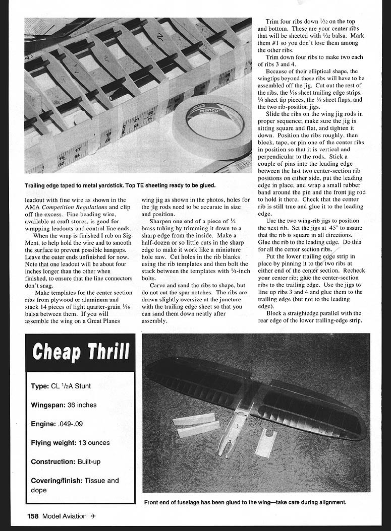
- Tape the top trailing-edge strip to a straightedge, position it, glue along the ribs, drop the top strip in place and pin it to the ribs. Use thin CyA to tack the rear of the trailing-edge strips together. When dry, remove any tape inside the trailing edge.
Spar notches and spars
- Use a straightedge and pencil to mark the top spar position on each rib. Make a rib-notching tool by gluing 220-grit sandpaper to a strip of 1/8" x 1/4" x 1". Glue a wider piece to the other side as a sanding stop.
- Carefully sand a spar notch in the top of each rib while the wing is on the jig.
- Check spar fit and glue the top spar in, except to ribs 3 and 4. The spar should sit slightly recessed so final sanding yields a smooth surface.
- Remove the wing from the jig and finish gluing the rear of the trailing-edge strips.
- Turn the wing over, spar down, on a flat surface. Mark, notch, check, and install the second spar. When dry, inspect the partially finished wing to ensure squareness.
Tips, tip ribs and leadout guide
- Sight down the wing tip, pinch the top and bottom spar tips together and glue (thick CyA plus accelerator is good).
- Glue the 1/4" sheet tip pieces between the trailing edge and the spars, centering them carefully.
- Slide rib 6 into place, mark spar positions, sand notches and glue rib 6. Repeat with rib 5 and the other tip. Add the 1/16" trailing web between tip ribs.
- Soak the unattached part of the leading edge by wrapping with wet paper towels for a few minutes, press into tip rib notches and glue.
- Install forward tip pieces, then cut out the inside tip and install the flattened 1/4" aluminum tubing leadout guide. Both leadouts exit one opening so control input will not make the airplane yaw.
- Install the 1/8" plywood bellcrank mount; block it up from inside the bottom spar with 1/4" square. Mark leadout positions on inside wing ribs, cut leadout holes with a Dremel and 1/8" ball cutter or sharp knife, and cut for bellcrank clearance.
- Install the flap pushrod in the bellcrank, run leadouts through the ribs and tip guide, then install the bellcrank. Fill below the bellcrank mount with scrap balsa for good glue contact with the bottom center-section sheeting. Sheet the wing center-section.
- Mark a centerline around the center-section sheeting and finish the outer ends of the leadouts. Glue three pennies in the outer wing for tip weight if needed.
False ribs, rigidity and finishing
- Use templates to position the false ribs. Trim towards the tips and sand to the airfoil contour after installation.
- Glue a vertical piece of hard 1/16" x 1/8" to the sides of each half-rib between the spars to increase wing rigidity.
- Use a long sanding block to assure the rear line of the trailing edge is straight so flaps can fit tightly.
- The wing can be covered now or later. It is rigid enough for plastic films. A two-inch-wide strip of lightweight glass cloth around the center section will help if you plan a larger engine.
Flaps
- Flaps are flat with rounded edges. Cover them with the same material as the wing.
- Make a flap horn similar to the elevator horn, but use more flexible steel wire (14 or 16 gauge), flexible enough to tweak flaps to correct any wing warp.
- Slip two pieces of 1/16" I.D. aluminum or brass tubing on either side of the flap horn before bending ends. Recess mounting tubing so the wire part of the horn is flush with the trailing edge.
- Install flaps with your favorite hinge method (figure-8 hinges made of dental floss work well). Cut small notches in the leading edge of the flaps so hinges don't push the flaps away from a tight fit. If flaps stick with later coats of dope, floss the hinge line to free them.
- Bend the flap pushrod to length with a right-angle bend to go through the flap control horn. You may make the pushrod in two overlapped pieces (1/2–3/8" overlap), wrap with beading wire and solder after careful adjustment for equal movement (about 30° each way).
Fuselage
- Cut a gluing jig for the forward sides from a balsa block.
- Cut the front sides from moderately hard 3/32" sheet and doublers from 1/32" plywood. Install 3/32" plywood inserts for the tank cover hold-down bolts.
- Glue a side and doubler with five-minute epoxy and clamp in the jig until dry. Make right and left sides.
- Cut 1/8" x 1/4" spruce or basswood rails for the tank cover and clamp to the sides. Drill for 3-48 bolts (use 2-56 bolts and nuts if 3-48s aren't available) and install blind nuts on the inside of the rails. Cut bolts off almost flush with the blind mounting nuts.
Engine crutch and tank mount
- For the 1/2A, make the engine crutch from 1/8" plywood for the engine mount, 1/8" balsa with grain across the crutch, and a 1/8" x 3/4" spruce piece for the rear tank mount hook. The tank is held in place with rubber bands.
- Drill engine mount holes and install 3-48 blind nuts. Glue two strips of 1/8" x 3/32" spruce down each side of the crutch bottom and trim to shape.
- For an .09, make the engine mount from 1/4" plywood and let it stick up 1/8" above the crutch. Install tank mounting hooks.
Landing gear
- Bend a landing gear from 1/16" piano wire and install in the landing gear mount. A removable gear allows field adjustments. Epoxy the gear wire to a cutout plywood triangle if making it removable; glue a scrap of 1/16" plywood to the rear of the gear sandwich to hold the gear in place. Drill the sandwich for a 3-48 blind nut and install it.
Assembly
- Put thin plastic pieces overlapping the bottom edges of the fuselage sides between the sides and the tank cover rails, then bolt them on.
- Install a temporary former to hold the front end square about where the bend of the sides starts.
- Assemble fuselage sides, crutch, and landing gear mount using 45-minute epoxy. Clamp, ensuring everything is square and straight. Glue the hard 1/16" balsa tank cover to its rails.
- Install the fuselage front on the wing on a flat surface. Tack-glue temporary spacers to the flap bearing tubes at the rear of the wing to hold it level. Line up centerline of the leading edge with fuselage centerline marks and tack the front end in place with CyA.
- Mix epoxy and microballoons to make a thick paste and form a small fillet around wing joints on the inside of the fuselage.
Rear fuselage and formers
- Cut rear fuselage sides from light 3/32" sheet. Glue to the wing, ensuring everything is square, pull together at the rear and glue to the 1/8" x 1/4" tail post. Be careful to center the rear of the fuselage.
- Cut rear formers from 1/16" sheet, check alignment and CyA them in.
Pushrods, horns and tail
- Make the elevator pushrod: flatten the end of a 1/16" I.D. brass tube and drill a 1/16" hole 1/8" from the end; cut the tube about 1" long. Insert free end of the flap pushrod through the 1/16" hole and solder on a washer to keep it in place.
- Solder a Kwik-Link on the end of a piece of 1/16" piano wire. Hinge the stab and elevator and attach the Kwik-Link to the elevator horn.
- Hold the tail assembly in place and measure the pushrod. Cut it so about 1/2" will insert into the brass tube at the flap horn with controls neutral. Sand this pushrod end shiny for a good solder joint.
- Install the pushrod and glue the stab in place, ensuring alignment. Adjust pushrod length and solder it into the brass tube. Confirm controls are free and there is no binding.
Tailskid and sheeting
- Bend the tailskid from 1/32" wire for the 1/2A; use 1/16" for the .09. Slip a small piece of fuel line or flexible tubing over the tailskid where it exits the fuselage to prevent fatigue at that point. Sew the tailskid to the 1/16" plywood mount with dental floss or beading wire, epoxy it and install the mount with epoxy.
- Sheet the bottom of the fuselage with 1/16" or 3/32" balsa.
Engine installation and nose
- Install engine and tank. Cut openings needed for needle valve, tank tubing, etc.
- Cut the nose ring from 1/16" plywood and tack-glue it to the back of the spinner with 1/16" balsa spacers in between. Put spinner and prop on engine and glue nose ring to fuselage.
- Glue in balsa filler blocks, cut the spinner loose and remove the engine. Shape the lower nose as desired.
- Glue in the top formers on the front fuselage. Fuelproof the blind nut side of the engine mount and any other places hard to reach after nose completion.
- Fuselage top can be planked with soft 1/8" square or 1/16" sheet, either completely or with stringers and tissue in the rear. Carve the front noseblock or build up out of sheet and hollow to about 7/16" to clear the engine crankcase.
Rudder and finishing
- Build up the rudder or use light 3/16" sheet for the .09. The rudder is hinged with copper wire so you can adjust for yaw if needed. Glue the fixed rudder in place, but install the movable rudder last.
- Fill dings or low spots with lightweight spackling compound mixed with a little water and Titebond to make a thick paste. Sand, apply a couple of coats of thin dope, and sand again.
- Cover the nose with light glass cloth or silk; cover the rest of the body with tissue or silkspan.
- Add 1/8" fillet strips for the flaps. Mask off wing fillet area, mix a thick paste of water, light spackling compound, microballoons and Titebond, and form fillets. Sand when dry and cover with tissue or silkspan using Titebond.
- Coat inside of the nose and tank compartment with epoxy for protection. Dope the fuselage until uniformly shiny, sanding lightly between coats.
Canopy
The canopy is a Sig five- or six-inch plastic canopy.
- Cut the canopy free from excess plastic. A Dremel tool with a saw blade helps—trim the flat plastic to within 1/4" of the canopy, then use the remaining flat plastic as a Dremel guide.
- Tape coarse sandpaper to the top of the fuselage and rub the canopy back and forth until it matches the fuselage contour.
- Attach canopy with your preferred method. For opaque canopies, thick CyA works well. An opaque canopy can be attached before or after final clear dope coats.
Power Plant
If the engine does not handle well and run right, nothing else matters. Install an engine you know. If using a new or unfamiliar engine, run it on a test stand with the airplane fuel system to get it tuned.
- TD .049 needs about 1.5 ounces of fuel to complete the AMA Stunt pattern; the .09 needs about 2.5 ounces.
- The tank should be uniflow: the pressure line should terminate about 3/8" forward of the fuel pickup tube. The tank is sealed except for pressure and fuel lines during running. If you don't run pressure, the uniflow acts as the tank vent.
- The 1/2A flies well on 42-foot .008 stranded lines (handle carefully). TD .09 airplanes fly fine on 52-foot .012 lines. I wipe lines with a paper towel and untwist them before each flight and at the end of the session.
- The smaller Sullivan control handle is light and works well, or make a custom handle from 1/4" plywood.
Flying
If you are patient and careful, the Cheap Thrill will give many pleasant flights. For the first flights, use just a half-tank of fuel and avoid anything radical.
- First flight goals: check that the airplane flies level and parallel to the circle.
- If one wing is noticeably high, tweak the flaps to level it.
- Start with about 1/8" rudder offset and adjust so you are looking directly down the wing in level flight. Ideally, no rudder offset will be needed.
- Once level and parallel, try climbs and dives to gauge control sensitivity. Fly a couple of high laps to see if the engine sags.
- Try a few loops and some inverted laps. If the outside wing flies low inverted, you have too much tip weight; if it flies high, you have too little. Adjust tip weight and tweak flaps as needed.
- Don't attempt anything more exciting than wingovers, loops, lazy eights and inverted flight until you and the engine are satisfied.
- When ready for competition, put in enough fuel for the AMA pattern. Fly the pattern through the horizontal square eights, then fly level until the engine quits. If it flies at least 20 more laps, you had plenty of fuel to finish the pattern.
You are on your own. Have fun!
— Jim Thomerson 1317 Eileen Collinsville, IL 62234
Transcribed from original scans by AI. Minor OCR errors may remain.

