
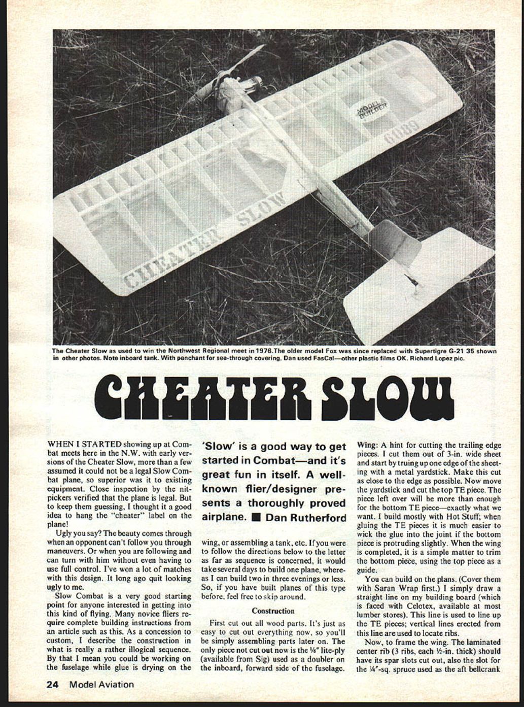
CHEATER SLOW
WHEN I STARTED showing up at Combat meets here in the N.W. with early versions of the Cheater Slow, more than a few assumed it could not be a legal Slow Combat plane, so superior was it to existing equipment. Close inspection by the nitpickers verified that the plane is legal. But to keep them guessing, I thought it a good idea to hang the "cheater" label on the plane.
Ugly you say? The beauty comes through when an opponent can't follow you through maneuvers. Or when you are following and can turn with him without even having to use full control. I've won a lot of matches with this design. It long ago quit looking ugly to me.
Slow Combat is a very good starting point for anyone interested in getting into this kind of flying. Many novice fliers require complete building instructions from an article such as this. As a concession to custom, I describe the construction in what is really a rather illogical sequence. By that I mean you could be working on the fuselage while glue is drying on the wing, or assembling a tank, etc. If you were to follow the directions below to the letter as far as sequence is concerned, it would take several days to build one plane, whereas I can build two in three evenings or less. So, if you have built planes of this type before, feel free to skip around.
'Slow' is a good way to get started in Combat—and it's great fun in itself. A well-known flier/designer presents a thoroughly proved airplane. ■ Dan Rutherford
Construction
First cut out all wood parts. It's just as easy to cut out everything now, so you'll be simply assembling parts later on. The only piece not cut out now is the 1/8" lite-ply (available from Sig) used as a doubler on the inboard, forward side of the fuselage.
Wing hint: cutting the trailing edge pieces. I cut them out of 3-in. wide sheet and start by truing up one edge of the sheeting with a metal yardstick. Make this cut as close to the edge as possible. Now move the yardstick and cut the top TE piece. The piece left over will be more than enough for the bottom TE piece—exactly what we want. I build mostly with Hot Stuff; when gluing the TE pieces it is much easier to wick the glue into the joint if the bottom piece is protruding slightly. When the wing is completed, it is a simple matter to trim the bottom piece, using the top piece as a guide.
You can build on the plans. (Cover them with Saran Wrap first.) I simply draw a straight line on my building board (which is faced with Celotex, available at most lumber stores). This line is used to line up the TE pieces; vertical lines erected from this line are used to locate ribs.
Now, to frame the wing. The laminated center rib (3 ribs, each 1/4-in. thick) should have its spar slots cut out, also the slot for the 1/8"-sq. spruce used as the aft bellcrank mount. Pin the bottom TE piece to the building board, being sure the forward edge piece is lined up straight with the reference line on the board and plans. Glue the three center ribs with Hot Stuff. Five-minute epoxy applied to the two 2-in. slots in the assembly bellcrank mount; the bottom spar is slipped into the slots. Don't wait for the epoxy to set up. Immediately lay the rib/spar assembly on the board and glue the bottom TE piece with Hot Stuff. Once properly lined up, a weight placed on the center rib will hold position until the epoxy sets. Notice the spar sits flat on the board as does the entire rib/spar assembly. I took the idea several months ago from Rich von Lopez's recent designs; it doesn't seem to hurt performance. An airfoil utilizing a flat board is a perfect simple jig.
Be sure the leading edge piece is glued to the center ribs and be sure the LE is aligned properly before gluing. Hot Stuff makes a perfect joint assuming parts are cut and fit accurately. Since I mentioned I build mostly with Hot Stuff, I'll specify hereafter the glue used—Hot Stuff.
Starting at the center of either wing panel, place the ribs and half-ribs and place glue, working your way to the tip. When the ribs are glued, add the top TE piece. The top spar is now glued in. It is wise to use epoxy on the spar/center rib joint, especially if the joint is a loose fit.
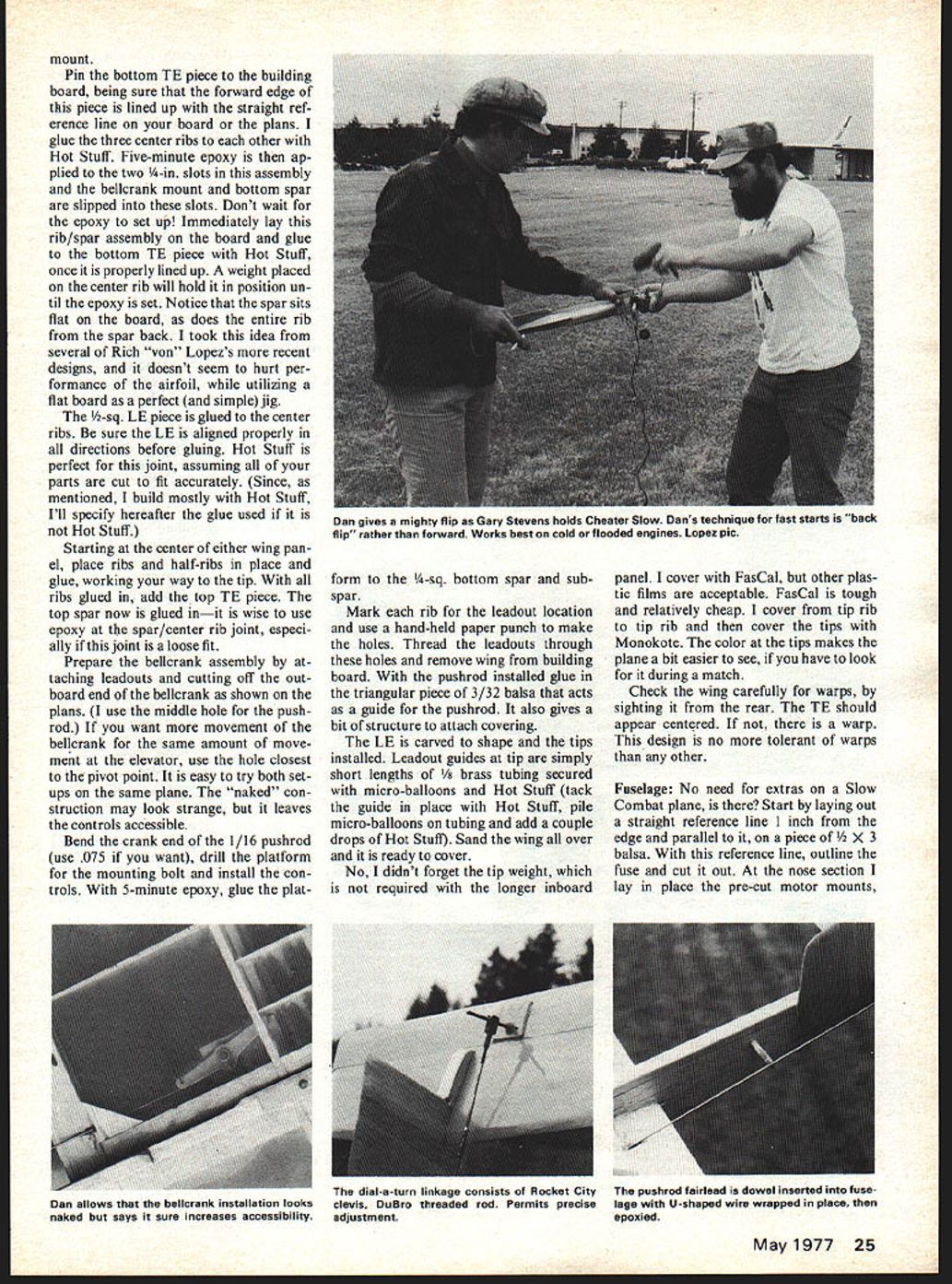
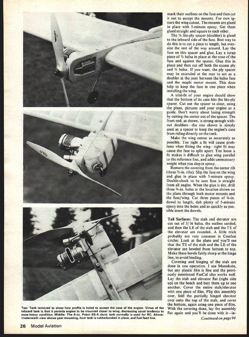
Prepare the bellcrank assembly, attaching leadouts and cutting off the outboard end. The bellcrank shown on the plans: use the middle hole if you want the movement of the bellcrank to be the same amount as the elevator; use the hole closest to the pivot point for less movement. It's easy to try both setups on the same plane. Naked construction may look strange, but it leaves the controls accessible. Bend the crank end for a 1/16" pushrod; I use .075. Drill the platform mounting bolt hole and install controls; glue the platform with 5-minute epoxy.
Mark rib leadout locations; use a hand-held paper punch to make holes. Thread the leadouts through the holes and remove the wing from the building board. With the pushrod installed, glue a triangular piece of 3/32 balsa to act as a guide for the pushrod and also give a bit of structure. Attach the covering, carve and shape the leading edge and install tips. Leadout guides at the tip are simply short lengths of brass tubing secured with micro-ball... oons and Hot Stuff (tack the guide in place with Hot Stuff, pile micro-balloons on the tubing and add a couple drops of Hot Stuff). Sand the wing all over and it is ready to cover.
No, I didn't forget the tip weight, which is not required with the longer inboard panel. I cover with FasCal, but other plastic films are acceptable. FasCal is tough and relatively cheap. I cover from tip rib to tip rib and then cover the tips with Monokote. The color at the tips makes the plane a bit easier to see, if you have to look for it during a match.
Check the wing carefully for warps, by sighting it from the rear. The TE should appear centered. If not, there is a warp. This design is no more tolerant of warps than any other.
Fuselage
No need for extras on a Slow Combat plane, is there? Start by laying out a straight reference line 1 inch from the edge and parallel to it, on a piece of 1/2 x 3 balsa. With this reference line, outline the fuse and cut it out. At the nose section I lay in place the pre-cut motor mounts, then install and secure them before fairing the nose to shape. The pushrod fairlead is dowel-inserted into the fuselage with a U-shaped wire wrapped in place and epoxied. Mark their outlines on the fuse and then cut it out to accept the mounts. For now ignore the wing cutout. The mounts are glued in place with 5-minute epoxy. Get them glued straight and square to each other.
The 1/8 lite-ply spacer (doubler) is glued to the inboard side of the fuse. Best way to do this is to cut a piece to length, but oversize the rest of the way around. Lay the fuse on this spacer and glue. Lay a scrap piece of 1/2 balsa in place at the nose of the fuse and against the spacer. Glue this in place and then cut off both the excess ply and 1/2 balsa. If you want, the ply spacer may be extended at the rear to act as a doubler at the joint between the balsa fuse and the maple motor mount. This does help to keep the fuse in one piece when installing the wing.
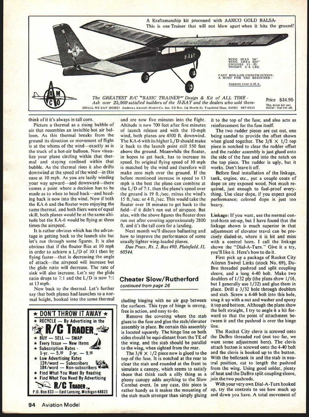
A trial-fit of your engine should show that the bottom of its case hits the lite-ply spacer. Cut out the spacer to clear, using the plans, pictures and your engine as a guide. Don't worry about losing strength by cutting the center out of the spacer. The front end, as shown, is strong enough without doublers — the one shown is simply used as a spacer to keep the engine's case from riding directly on the tank.
Make the wing cutout as accurately as possible. Too tight a fit will cause problems when fitting the wing — tight fit may cause the fuse to split apart. Too loose a fit makes it difficult to glue wing parallel to the reference line, and adds unnecessary weight when you slop in epoxy.
Remove the covering from the center rib (three 1/2-in. ribs). Slip the fuse on the wing and glue in place with 5-minute epoxy. Double-check to be sure fuse is straight from all angles. When the glue is dry, drill three 1/4-in. holes at the location shown on the plans through both motor mounts and the fuse/wing. Cut three pieces of 1/4-in. dowel to length, dab plenty of 5-minute epoxy into the holes and as quickly as possible insert the dowels.
Tail Surfaces:
The stab and elevator are cut out of 3/16 balsa, the outline sanded, and then the LE of the stab and the TE of the elevator are rounded. A little trick probably not very common in Combat circles: Look at the plans and you'll see that the TE of the stab and the LE of the elevator are beveled from bottom to top. Make these bevels fairly sharp at the hinge line, to avoid binding.
Covering and hinging of the stab are done in one operation. I use Monokote, but any plastic film is fine and the previously mentioned FasCal also works well. Lay the stab and elevator flat (right side up) on the bench and butt them up to one another. Cover the entire stab/elevator with one piece of film. Flip this assembly over, fold the partially hinged elevator over onto the top of the stab, and cover the bottom, again using one piece of film. With the covering done, lay the assembly flat again and you'll be done with it — in
Cheater Slow/Rutherford
continued from page 26
including hinging with no air gap between the surfaces. This type of hinge is strong, free in action, and easy to do.
Remove the covering where the stab glues to the fuse and glue the stab/elevator assembly in place. Be certain this assembly is located squarely. The hinge line on both sides should be equi-distant from the TE of the wing, and the stab should be parallel to the wing, when sighted from the rear.
The 3/8 x 1/2 piece now is glued to the top of the fuse. It is notched at the rear to clear the stab and rounded at the front to simulate a canopy, which seems to satisfy those that think such a silly thing as a phony canopy adds anything to the Cheater Combat event. In any case, this piece is rather handy as it makes the mounting of the stab much stronger than simply gluing it to the top of the fuse, and also acts as reinforcement for the fuse itself.
The two rudder pieces are cut out, one being sanded to provide the offset shown when glued together. The 3/8 x 1/2 top piece is notched to clear the rudder offset and the rudder assembly is just glued onto the side of the fuse and into the notch on the top piece. The rudder is ugly, but it works. Don't leave it off.
Before final installation of the linkage, tank, engine, etc., put a couple coats of dope on any exposed wood. Not much required, just enough to fuel-proof everything. Use clear dope, if you expect good performance; colored dope is just too heavy.
Linkage:
If you want, use the normal control-horn set-up, but I have found that the linkage shown is much superior in that adjustment of elevator travel can be precisely dialed-in, where it is hit and miss with a control horn. I call the linkage shown the "Dial-A-Turn." Give it a try, you'll like it. Here's how to do it.
First pick up a package of Rocket City Aileron Swivel Links (stock No. 69), Du-Bro threaded pushrod and split coupling sleeve, and a long 4-40 bolt. Make two doublers of 1/32 ply (the plans show 1/16, but I generally use 1/32) and glue them in place. Drill a 3/32 hole through doublers and stab. Screw a 4-40 bolt into this hole, snug it up with a nut and washer and epoxy it top and bottom. Although the plans show the bolt straight, I try to angle it a bit forward so that the point of attachment between it and the pushrod is over the hinge line.
The Rocket City clevis is screwed onto the DuBro threaded rod (not too far, we want some adjustment here). The clevis attach button is screwed onto the 4-40 bolt and the clevis is hooked up to the button. With the bellcrank in and the stab in neutral position, cut to length the pushrod from the wing. Using good solder, plenty of heat and the DuBro split coupling sleeve, join the two pushrods.
With your very own Dial-A-Turn hooked up, try the controls to see how much up and down you have. A total movement of 3/4 in. is about right for starters (3/4 up, 3/8 down). This will probably be too much or too little, but the control system allows full adjustment to suit your tastes.
A pushrod guide is an absolute necessity. I drill a 1/8 hole through the fuse, glue in a piece of 1/8 dowel and then make a U-shaped piece of 1/32 wire. This wire is wrapped onto the dowel with wrapping wire, which is epoxied. Not pretty, but it works.
Engine, Fuel System: The placement of the tank on the inboard side of the fuse isn't all that unusual. Many people are using it because it allows moving the engine back a bit towards the wing, which helps get rid of the nose heavy condition seen in most Slow Combat designs. The tank is a Pylon SS-4 clunk normally used in RC planes. This tank works better than any I have tried. It is cheap, easy to make and mount, vibration doesn't bother it as there are no solder joints to break or leak. With the 4-oz. capacity it gives engine runs of over 5 minutes—super engine runs if the needle is set properly. More on this later. Look at the pics. The single vent goes to the top, forward and inboard-most corner of the tank. When assembling the tank, be sure this vent is not closed off, due to being jammed against the tank. There is no need for having the vent go up above the tank. I cut this vent off short, leaving a straight piece about 1/4 in. long protruding from the plug in the tank.
The feed line is per tank instructions. Just be sure the clunk weight will reach both the top and bottom corners of the tank. The external, brass feed line is bent so that it goes straight to the needle valve and is not in the way of the prop. Use a fuel filter.
Wire clips are bent from 1/32 wire. These go on the fuse behind the engine; rubberbands attached to them hold the tank in position.
I regard blind nuts as too much trouble to install. They would interfere with the tank anyway. I use sheet metal screws. They work fine. Obtain #6 X 1/4 panhead sheet-metal screws. A pilot hole is required—3/32 in. works fine. Punch the holes in and install your engine. The screws will go in hard the first time but will work easier afterwards. Use of these screws will mean drilling out the mounting bolt holes in your engine. You should be using #6 screws anyway, even if you use blind nuts.
Miscellaneous: Install the engine. Double-check for warps. Be sure the prop clears the tank and its assorted lines. So far, the engine I prefer for Slow Combat is the newest version Super Tigre G-21 35. It has adequate power, starts easily and draws fuel very well, important in an event limited to suction feed.
For props, you have choices. The Rev-Up 9 X 7 is fine, although quite hard to find in any decent quantities. However, the very best prop I have found for Slow Combat is the Taipan 9 X 6. It really pulls through maneuvers and just generally works great. The only modification necessary is to remove the flashing from the LE and TE of the prop so you won't get cut while flipping it.
As a rule, we here in the N.W. go conservative on nitro in Slow Combat, yet we seem to fly as fast as anybody else. Speed is not the most important thing in Combat, especially Slow Combat. Much more important are easy starts (the one-flip kind), needle settings that are easy to get, and consistent runs from maneuver to maneuver, match to match. So we rarely use fuels with a nitro content of more than 20%. I use either Nitrotane 20% or Aldrich's Magnum 10%. Both fuels are excellent with the Magnum giving longer runs on the same amount of fuel. This is not a problem with the 4 oz. tank on the Cheater Slow; it'll give 5-minute-plus runs on most any fuel, but is something to consider if you use smaller tanks.
Flying: I'm hoping that you have followed my recommendations as to motor, tank, etc. because this plane was designed with only one combination in mind. For instance, use of a lighter motor will find you out at the field with a tail-heavy plane. Might be quite exciting for the first minute before the crash, but is definitely a situation to be avoided! the turns and then back off a little to give the tightest, fastest turns possible.
This plane works very well in the "wiggly" maneuvers now gaining in popularity here on the West Coast. So try flying it in a rather jerky fashion, doing lots of reversals of direction in quick succession. In practice flying, I try to force myself never to do a complete half loop, let alone a full loop, both of which are easy maneuvers for someone to follow through. And never do a lazy 8—this maneuver is extremely easy to follow, unless you can do them with the bottoms a foot or so off the ground without watching your plane. In this case, lazy 8's are a great way to suck your opposition into the ground.
On this first flight, also keep track of how your engine runs. If it cuts rich on outside loops, it is too rich. If the tank still has fuel in it (1 or 2 oz.) when the engine quits, your engine is not completely broken in. With a well broken-in engine, the previously suggested props, a tank made per the plans and pictures, 10% to 20% fuel, and the right needle setting, you can expect super runs. The engine will run at a constant speed through any maneuver you can dream up and the setting will not go lean at the end of the tank.
Transcribed from original scans by AI. Minor OCR errors may remain.

