
Chipmonk 9
Peter Tindal
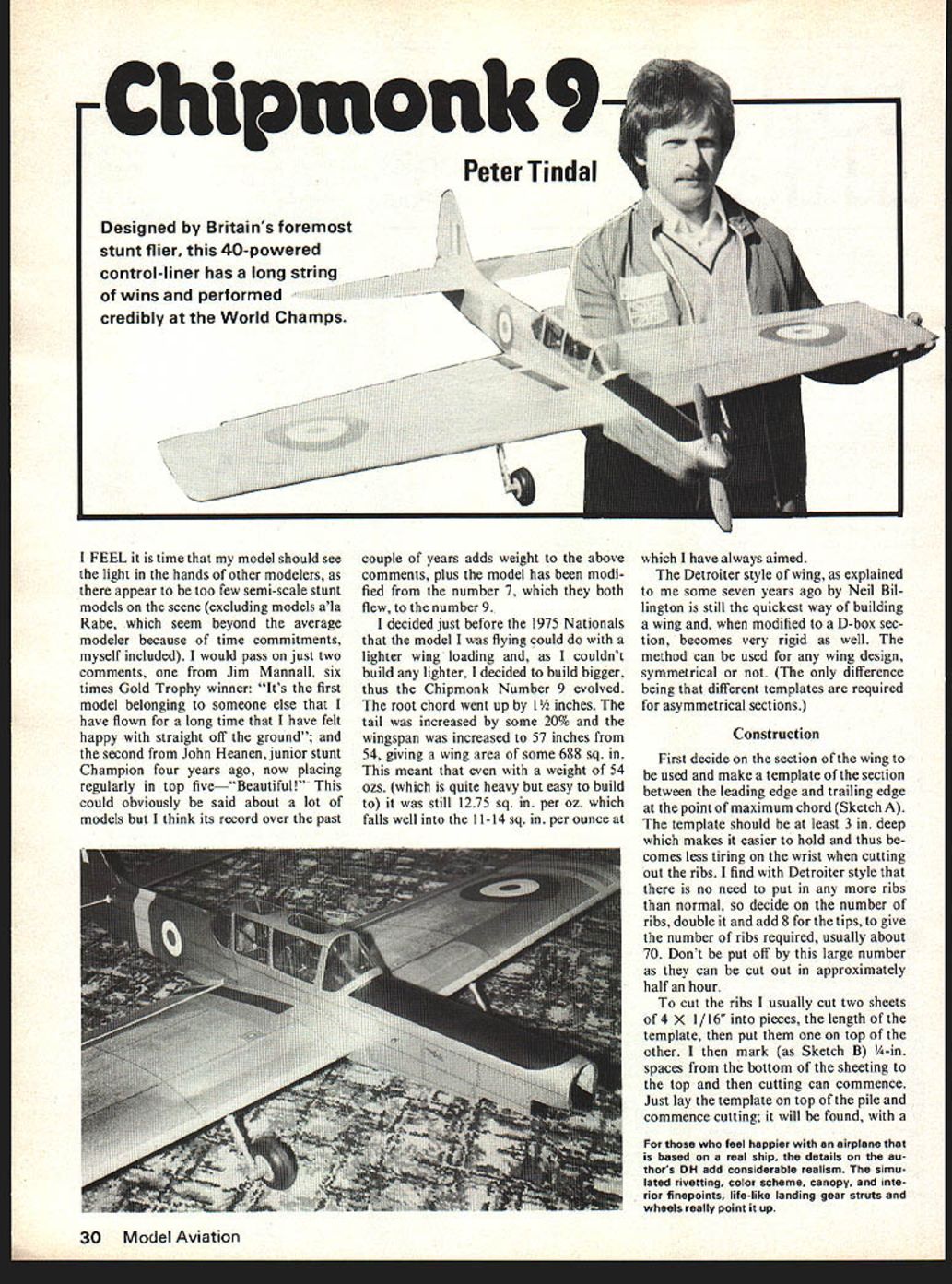
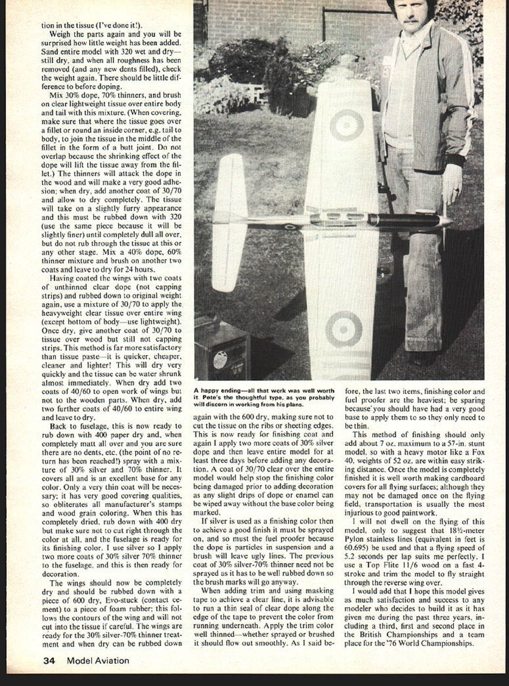
Designed by Britain's foremost stunt flier, this 40-powered control-liner has a long string of wins and performed credibly at the World Champs.
I FEEL it is time that my model should see the light in the hands of other modelers, as there appear to be too few semi-scale stunt models on the scene (excluding models a la Rabe, which seem beyond the average modeler because of time commitments, myself included). I would pass on just two comments, one from Jim Mannall, six times Gold Trophy winner: "It's the first model belonging to someone else that I have flown for a long time that I have felt happy with straight off the ground"; and the second from John Heanen, junior stunt Champion four years ago, now placing regularly in top five—"Beautiful!" This could obviously be said about a lot of models but I think its record over the past couple of years adds weight to the above comments, plus the model has been modified from the number 7, which they both flew, to the number 9.
I decided just before the 1975 Nationals that the model I was flying could do with a lighter wing loading and, as I couldn't build any lighter, I decided to build bigger. Thus the Chipmonk Number 9 evolved. The root chord went up by 1½ inches. The tail was increased by some 20% and the wingspan was increased to 57 inches from 54, giving a wing area of some 688 sq. in. This meant that even with a weight of 54 ozs. (which is quite heavy but easy to build to) it was still 12.75 sq. in. per oz., which falls well into the 11-14 sq. in. per ounce at which I have always aimed.
The Detroiter style of wing, as explained to me some seven years ago by Neil Billington, is still the quickest way of building a wing and, when modified to a D-box section, becomes very rigid as well. The method can be used for any wing design, symmetrical or not. (The only difference being that different templates are required for asymmetrical sections.)
Construction
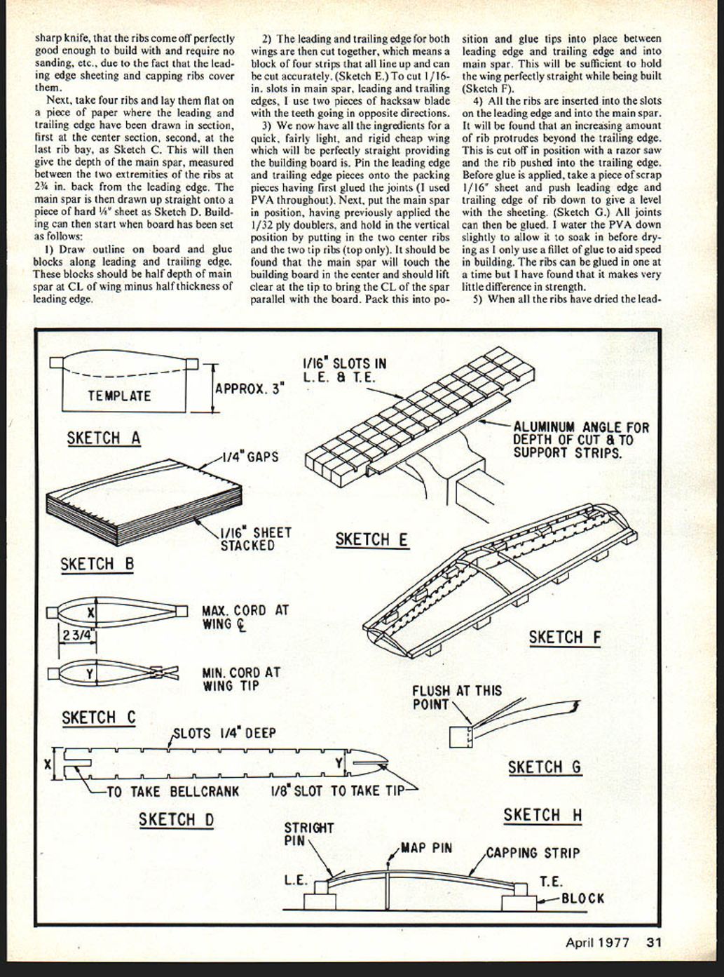
First decide on the section of the wing to be used and make a template of the section between the leading edge and trailing edge at the point of maximum chord (Sketch A). The template should be at least 3 in. deep which makes it easier to hold and thus becomes less tiring on the wrist when cutting out the ribs. I find with Detroiter style that there is no need to put in any more ribs than normal, so decide on the number of ribs, double it and add 8 for the tips, to give the number of ribs required, usually about 70. Don't be put off by this large number as they can be cut out in approximately half an hour.
To cut the ribs I usually cut two sheets of 4 x 1/16 in. into pieces, the length of the template, then put them one on top of the other. I then mark (as Sketch B) 1/4-in. spaces from the bottom of the sheeting to the top and then cutting can commence. Just lay the template on top of the pile and commence cutting; it will be found, with a sharp knife, ribs come off perfectly good enough to build and require no sanding, etc., due to the fact leading edge sheeting capping ribs cover.
Next take four ribs, lay flat on a piece of paper with the leading and trailing edges drawn. Section the first centre section, second last rib bay. Sketch C will give the depth of the main spar measured between the two extremities, ribs two back from the leading edge. The main spar is drawn up straight onto a piece of hard 1/32 in. ply (Sketch D).
Building can start. The board has to be set as follows: 1 Draw outline of the board; glue blocks along leading and trailing edges. Blocks should be half depth of main spar (CL wing minus half thickness leading edge). 2 The leading and trailing edge for both wings cut together means blocks — four strips — line up so you can cut accurately (Sketch E). Cut 1/16 in. slots for main spar, leading and trailing edges using two pieces of hacksaw blade with teeth going opposite directions. 3 We now have the ingredients for a quick, fairly light, rigid, cheap wing which will be perfectly straight providing the building board is true. Pin leading edge and trailing edge pieces onto packing pieces having first glued the joints (I used PVA throughout). Next put the main spar in position having previously applied 1/32 ply doublers. Hold vertical position by putting two centre ribs and two tip ribs on top. It will be found the main spar will touch the building board; centre should lift clear and tip bring CL spar parallel to the board. Pack positions, glue tips, place between leading and trailing edge and the main spar will be sufficient to hold the wing perfectly straight while being built (Sketch F). 4 All ribs inserted in slots in leading edge and main spar will be found increasing amounts of rib protrude beyond the trailing edge; cut off to position with a razor saw, rib pushed back to trailing edge. Before glue is applied take a piece of scrap 1/16 in. sheet, push leading and trailing edge rib down to give level sheeting (Sketch G). Joints can be glued with water PVA, down slightly to allow soak before drying; use fillet glue to aid speed building. Ribs can g... lue in one at a time but I have found that it makes very little difference in strength.
5) When all the ribs have dried the lead- ing edge sheeting can be applied. I cut this from a 4-in. sheet and the remainder goes along the trailing edge. If working fairly swiftly the glue can be applied first to all the ribs then along the leading edge and sheet, then pinned in position. Due to the lip caused by lowering the ribs, I find it only necessary to pin at each rib but not through it. (Sketch H.) Run the glue along the main spar and work sheeting onto ribs, pin to main spar. Here, I use large-head map pins so that the sheet doesn't raise up the pin.
Repeat process on other wing and at trailing edge, then add center section sheeting, capping strips and tip ribs. The tip ribs have capping strips as have the tips; this gives a definite flatness to each rib and reduces distortion of the tissue between ribs. Top of wing is now complete and should be left 24 hours before removing from board.
So far, time taken from cutting out template is in the region of three hours actual work which is normally spread over a few evenings. Do not trim leading edge or trailing edge as the wing has to be turned over and mounted on the same blocks.
6) The wing is then removed and turned through 180° about the CL and repinned to the jig. The bellcrank is added to the point which also forms the main center section brace and this is epoxied to the rear of the main spar. The leadouts are connected to the bellcrank and the guides fixed to the tip. The undercarriage is bent to shape from 10-swg piano (swg means standard wire gauge — equivalent is .128) wire (should the model be required for use over grass it is suggested that it be at least an inch longer) and wired (soft copper) to the ply brace. This is positioned at an angle from the bottom edge of the main spar to the uppermost edge of the leading edge. The area between the ply and the sheeting is filled with soft scrap balsa. I fill this area then sand it to the line of the two adjoining ribs so the bottom leading edge sheeting adheres to the whole surface. The same process from No. 4 is repeated and, after 4-6 evenings' work, a completed wing is ready for sanding to shape.
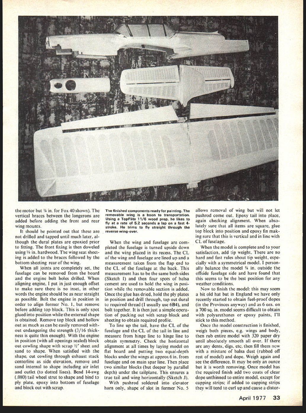
This is the process for building any Detroiter-style wing including "Chipmonk 9." Building the rest of the Chipmonk is fairly straightforward, the only complications being the removable wing.
The fuselage is built upside down on the plan as this is the best method of obtaining symmetry. Having cut out the formers, remembering No. 5 is 1/32 ply on both sides of 1/4 balsa (soft) and the fuselage sides (again including 1/32 ply doublers), the bearers are placed in position on the plan. Formers 3 and 4 are epoxied into place, making sure that they are both vertical and square. The fuselage sides are then epoxied onto the bearers and formers, making sure that the top of the sides are flat onto the building board.
Allow this to set while cutting four longerons from 1/4 stock. These can be glued in place using PVA or similar. The tailpost is glued into position by pulling sides to meet it. At this point making sure that the sides align with the plan, add former No. 2, again making sure it is square. The two wing seat braces are now glued into position together with the tank bay base (the thickness of this will vary according to the height of the venturi on the motor but 1/4 in. for Fox 40 shown). The vertical braces between the longerons are added before adding the front and rear wing mounts.
It should be pointed out that these are not drilled and tapped until much later, although the dural plates are epoxied prior to fitting. The front fixing is then doweled using 1/8 in. hardwood. The wing seat sheeting is added to the braces followed by the bottom sheeting rear of the wing.
When all joints are completely set, the fuselage can be removed from the board and the engine bolt holes drilled. When aligning engine, I put in just enough offset to make sure there is no inset, in other words the engine should be as near straight as possible. Bolt the engine in position in order to align former No. 1, but remove before adding top block. This is only spot glued into position while the external shape is obtained. Remove top block and hollow out as much as can be easily removed without endangering the strength (3/16 in. thickness is quite thin enough). With the engine in position (with all openings sealed) block out cowling shape with scrap 1/8 in. sheet and sand to shape. When satisfied with the shape, cut cowling through exhaust stack centreline as side elevation, remove and sand internal to shape including air inlet and outlet (to dotted lines). Bend 14-swg (.080) tail wheel strut to shape and bind to ply plate, epoxy into bottom of fuselage and block out with scrap.
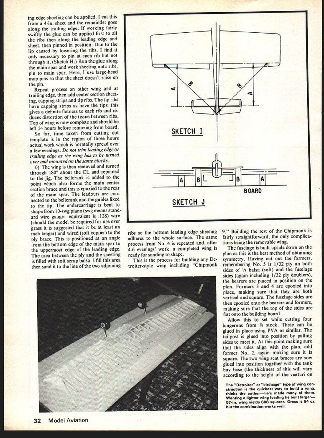
When the wing and fuselage are completed the fuselage is turned upside down and the wing placed into its recess. The CL of the wing and fuselage are lined up and a measurement taken from the flap end to the CL of the fuselage at the back. This measurement has to be the same both sides (Sketch I) and then four spots of balsa cement are used to hold the wing in position while the removable section is added. Once the glue has dried, hold the ply plates in position and drill through, tap out dural to required thread (I usually use 6BA), and bolt together. It is then just a simple operation of packing out with scrap block and sheeting to obtain required profile.
To line up the tail, have the CL of the fuselage and the CL of the tail in line and measure from hinge line to hinge line to obtain symmetry. Check the horizontal alignment at all times by laying model on flat board and putting two equal-depth blocks under the wings at approx 6 in. from fuselage and on main spar line. Then place two similar blocks (but deeper by parallel depth) under the tailplane. This ensures a true tail and wing horizontally (Sketch J).
With pushrod soldered into elevator horn only, shape of slot in former No. 5 allows removal of wing but will not let pushrod come out. Epoxy tail into place, again checking alignment. When absolutely sure that all items are square, glue top block into position and epoxy fin making sure that this is vertical and in line with CL of fuselage.
When the model is complete and to your satisfaction, add tip weight. There are no hard and fast rules about tip weight, especially with a symmetrical model. I personally balance the model 1/8 in. outside the offside fuselage side and have found that this seems to be the best position for any weather conditions.
Now to finish the model: this may seem a bit old hat but in England we have only recently started to obtain fuel-proof dope (in the Provinces anyway) and as on a 700 sq. in. model seems difficult to obtain with polyurethanes or epoxy paints, I'll stick to this method.
Once the model construction is finished, weigh both pieces, e.g. wings and body, then rub entire model with 320 paper dry until absolutely smooth all over. If there are any dents, digs, etc., then fill them now with a mixture of balsa dust (from rest of model) and dope. Weigh again and see the difference. It may be only an ounce but it is worth removing. Once model has the required finish add two coats of clear dope unthinned to entire model, except for capping strips; if added to capping strips they will tend to curl up and cause a distort-
Chipmonk 9
Designed by Britain's foremost stunt flier, the .40-powered control-liner has a long string of wins and has performed credibly at World Champs. I feel the time has come that the model should see the light of other modelers' hands; there appear to be too few semi-scale stunt models on the scene. Excluding models ala Rabe, which seem beyond the average modeler because of time commitments (myself included), I would pass just two comments: Jim Mannall, six-times Gold Trophy winner — its first model belonging to someone else — I have flown for a long time and have felt happy straight off the ground; second, John Heanen, junior stunt Champion four years ago, now placing regularly in the top five.
Beautiful could obviously be said about a lot of models. I think its record over the past couple of years adds weight to the above comments, plus the model has been modified a number of times. Both (flew) number 7; both flew number 9. I decided just before the 1975 Nationals that for model flying I could have a lighter wing loading — I couldn't build lighter, so I decided to build bigger. Thus Chipmonk Number 9 evolved. Root chord went up 1 inch, tail increased some 20%, wingspan increased to 57 inches (from 54), giving wing area some 688 sq in. This meant weight about 54 oz — quite heavy but easy build. Still 12.75 sq in per oz falls well within 11–14 sq in per ounce.
I have always aimed for a Detroiter-style wing (explained some seven years ago by Neil Billington) — still the quickest way of building a wing. The modified D-box section becomes very rigid. Well, the method can be used on any wing design, the only difference being the different templates required for asymmetrical sections.
Construction
First decide the section of wing to be used and make a template. The section is between the leading edge and the trailing edge at the point of maximum chord. The sketch template should be at least 3" deep — this makes it easier to hold and thus less tiring on the wrist when cutting out ribs. You'll find with the Detroiter style there is no need to put in normal cap strips. Decide the number of ribs — double at the tips to give the number of ribs required; usually about 70. Don't put off the large number; you can cut them out in approximately half an hour. Cut ribs usually from two sheets 4' x 1/16" (length of template); put one on top of the other and mark Sketch B. At A — in spaces bottom sheeting/top — cutting can commence. Just lay template on top of the pile and commence cutting; you will find it feels happier.
Airplane based on real ship details: the author's D.H. add considerable realism — simulated riveting, color scheme, canopy interior fine points, life-like landing gear struts and wheels really point up the model. With a sharp knife ribs come off perfectly and are good enough for the build and require no sanding etc., due to the fact that leading edge sheeting and capping ribs cover.
Next, take four ribs, lay flat on a piece of paper. The leading and trailing edge have drawn the section: first centre section, second last rib bay. Sketch C will give the depth of the main spar measured between the two extremities of ribs 2 back from the leading edge. The main spar is drawn up straight onto a piece of hard/soft sheet — Sketch D.
Building can start. The board has been set as follows:
- Draw outline on board and glue blocks along leading and trailing edge. Blocks should be half the depth of the main spar. CL wing minus half thickness leading edge.
- The leading and trailing edge of both wings cut together; means block four strips line up can cut accurately — Sketch E. Cut 1/16 in slots for main spar and leading/trailing edges using two pieces of hacksaw blade with teeth going in opposite directions.
- We now have the ingredients for a quick, fairly light, rigid, cheap wing which will be perfectly straight provided the building board is true. Pin leading edge and trailing edge pieces onto packing pieces having first glued joints — use PVA throughout. Next put main spar in position having previously applied 1/32 ply doublers to hold vertical position. Putting two centre ribs and two tip ribs on top you should find main spar will touch building board at centre and should lift clear at tip; bring CL spar parallel to board. Pack position, glue tips in place between leading edge, trailing edge and main spar; this will be sufficient to hold the wing perfectly straight while being built — Sketch F.
- All ribs inserted into slots in leading edge and main spar will be found. The increasing amount each rib protrudes beyond the trailing edge should be cut off to the correct position with a razor saw — rib pushed against trailing edge. Before glue is applied take a piece of scrap 1/16" sheet and push leading edge and trailing edge rib down to give level sheeting — Sketch G. Joints can be glued with water PVA, down slightly to allow soak before drying. Use fillet glue to aid speed building; ribs can g
ribs can go together perfectly — good enough for the build and requiring no sanding, etc., due to the fact leading edge sheeting and capping cover the ribs.
Next take four ribs, lay flat on a piece of paper and draw the leading and trailing edge line. Have drawn the section for the first centre section and the second last rib bay. Sketch C will give the depth of the main spar measured between the two extremities of ribs two back from the leading edge. Draw the main spar up straight onto a piece of hard 1/8" sheet — Sketch D.
- Draw the outline on the board and glue blocks along the leading and trailing edge. Blocks should be half the depth of the main spar (CL wing) minus half the thickness of the leading edge.
- The leading and trailing edges for both wings are cut together. This means block four strips line up and can be cut accurately — Sketch E. Cut 1/16" slots for the main spar and leading/trailing edges using two pieces of hacksaw blade with the teeth running in opposite directions.
- We now have the ingredients for a quick, fairly light, rigid, cheap wing which will be perfectly straight provided the building board is true. Pin the leading edge and trailing edge pieces onto packing pieces having first glued the joints — use PVA throughout. Next put the main spar in position having previously applied 1/32" ply doublers to hold vertical position. Putting two centre ribs and two tip ribs on top you should find the main spar will touch the building board at the centre and should lift clear at the tip; bring the CL spar parallel to the board. Pack the position, glue the tips in place between leading edge, trailing edge and main spar; this will be sufficient to hold the wing perfectly straight while being built — Sketch F.
- With all ribs inserted into the slots in the leading edge and main spar you will find the increasing amount each rib protrudes beyond the trailing edge should be cut off to the correct position with a razor saw — rib pushed against the trailing edge. Before glue is applied take a piece of scrap 1/16" sheet and push the leading and trailing edge rib down to give level sheeting — Sketch G. Joints can be glued with water PVA, down slightly to allow soak before drying. Use fillet glue to aid speed building. Ribs can go together quickly.
Transcribed from original scans by AI. Minor OCR errors may remain.

