
Church Midwing
Norm Rosenstock
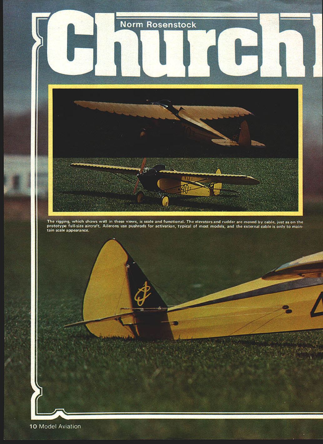
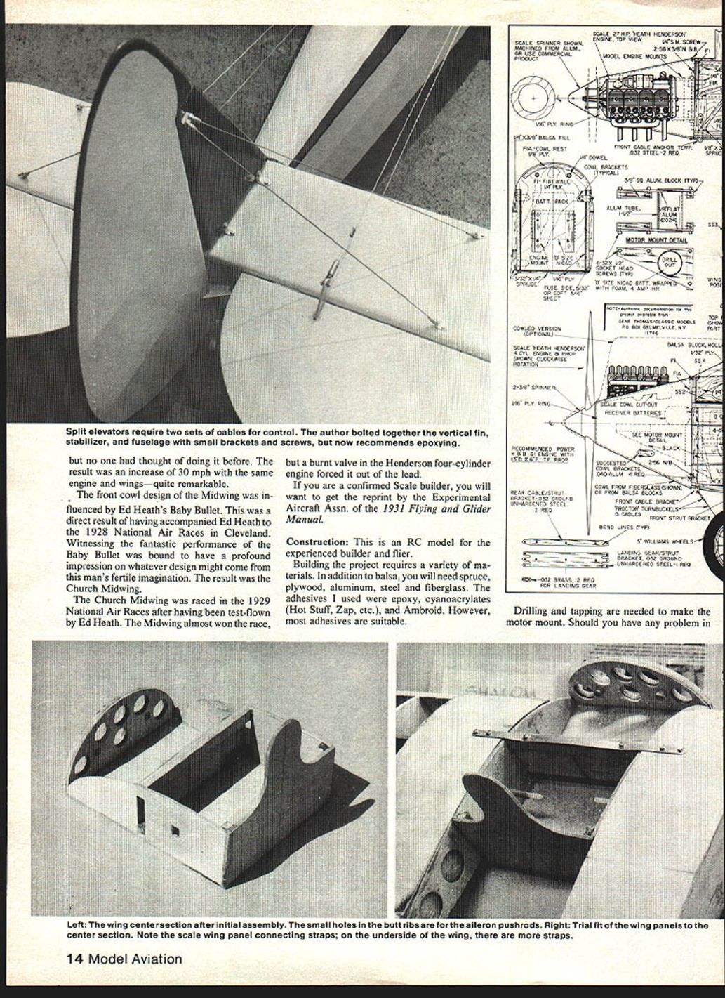
The rigging, which shows well in these views, is scale and functional. The elevators and rudder are moved by cable, just as on the prototype full‑size aircraft. Ailerons use pushrods for activation, typical of most models; the external cable is only to maintain scale appearance.
Like most R/C fliers, I had been promising myself for years that, if I could find the right airplane, I would build a beautiful scale model. My day came in 1977 at the WRAMS Show in Westchester, NY. At the Classic Models booth I found Gene Thomas' 1‑1/2‑in. scale Church Midwing. It had a 39‑1/2 in. wingspan, a four‑channel radio (small Cannon) and a Cox .049 engine — a fine little model but smaller than I wanted. I thought about 2‑in. scale (about 53 in. span) but wanted something larger, perhaps for a .60 engine.
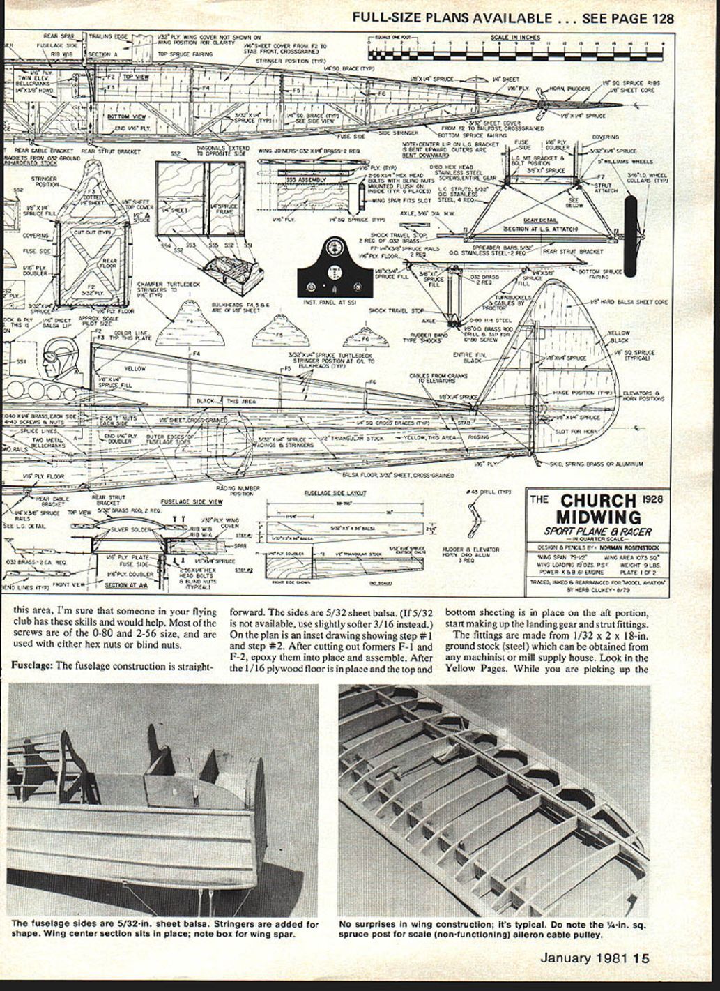
Quarter scale was the vogue, and the Church at quarter size was the best of both worlds. At this scale the airplane spans 79‑1/4 in. and has a wing area of about 1,073 sq. in. (slightly less than 7‑1/2 sq. ft.). At about 9 lb., wing loading would be roughly 19 oz. per sq. ft., so a .60 displacement engine would be adequate. It made an excellent first stand‑off/quarter‑scale model.
Armed with the 1‑1/2‑in. plans and the documentation booklet from Classic Models, I started to scale up the plans. It was relatively simple: essentially double everything. Gene Thomas had made two modifications on the 1‑1/2‑in. model: extended landing gear and enlarged tail surfaces. I chose the quarter‑scale landing‑gear position shown on the plans and used the enlarged tail surfaces.
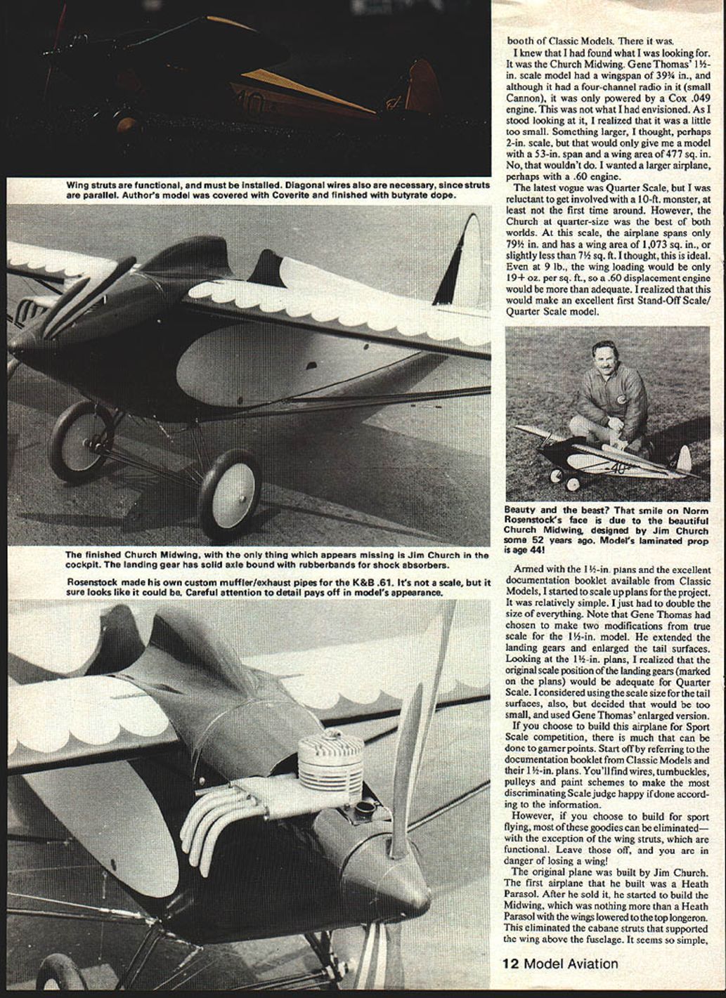
If you build this airplane for Sport Scale competition there is much you can do to garner points. Refer to the Classic Models documentation and the 1‑1/2‑in. plans for wires, turnbuckles, pulleys and paint schemes to satisfy the most discriminating scale judge. If you build for sport flying most of these scale items can be omitted — except for the wing struts, which are functional; leave those off and you risk losing a wing!
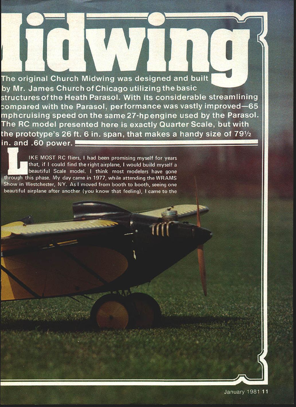
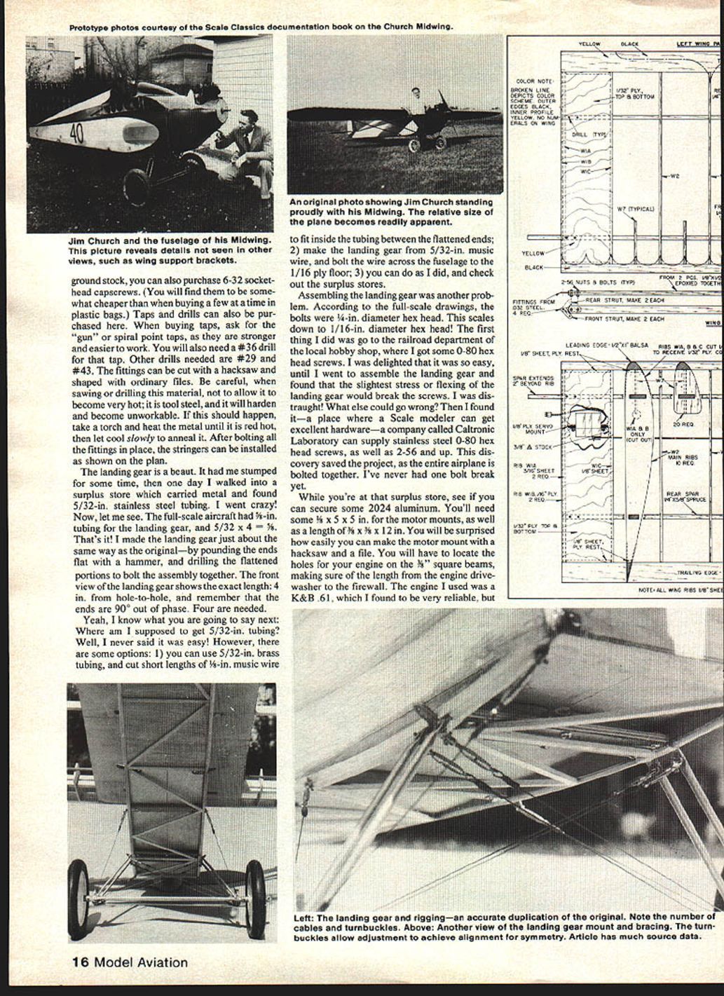
The original full‑scale plane was built by Jim Church. His first airplane was a Heath Parasol; after he sold it he built the Midwing, which was basically a Heath Parasol with the wings lowered to the longeron, eliminating the cabane struts that supported the wing above the fuselage. The result was an increase of about 30 mph with the same engine and wings — quite remarkable.
The front cowl design of the Midwing was influenced by Ed Heath's Baby Bullet after Church accompanied Heath to the 1928 National Air Races. The Midwing was raced in the 1929 National Air Races; it nearly won until a burnt valve in the Henderson four‑cylinder engine forced it out of the lead.
If you are a confirmed scale builder, get the reprint by the Experimental Aircraft Association of the 1931 Flying and Glider Manual.
Construction
This is an R/C model for the experienced builder and flyer.
Building the project requires a variety of materials and skills. In addition to balsa, you will need spruce, plywood, aluminum, steel and fiberglass. The adhesives I used were epoxy, cyanoacrylates (Hot Stuff, Zap, etc.) and Ambroid, though most adhesives are suitable. Drilling and tapping are needed to make the motor mount; if you lack these skills someone in your club can likely help. Most screws are 0‑80 and 2‑56, used with either hex nuts or blind nuts.
Materials and equipment (highlights)
- Balsa (various sheets), spruce, plywood
- Aluminum (motor mount plates, spinner)
- Steel (ground stock for fittings, tubing for landing gear)
- Fiberglass (cowling, fairings) — balloon method recommended
- Adhesives: epoxy (slow and fast), cyanoacrylates, Ambroid
- Taps/drills: #36 tap, drills #29 and #43, gun/spiral‑point taps recommended
- Hardware: 0‑80 and 2‑56 screws; stainless steel preferred
- Engine: K&B .61 used on my model; most sport .60 engines will do
- Radio: brick‑type unit (receiver + three servos) used for convenience
Fuselage
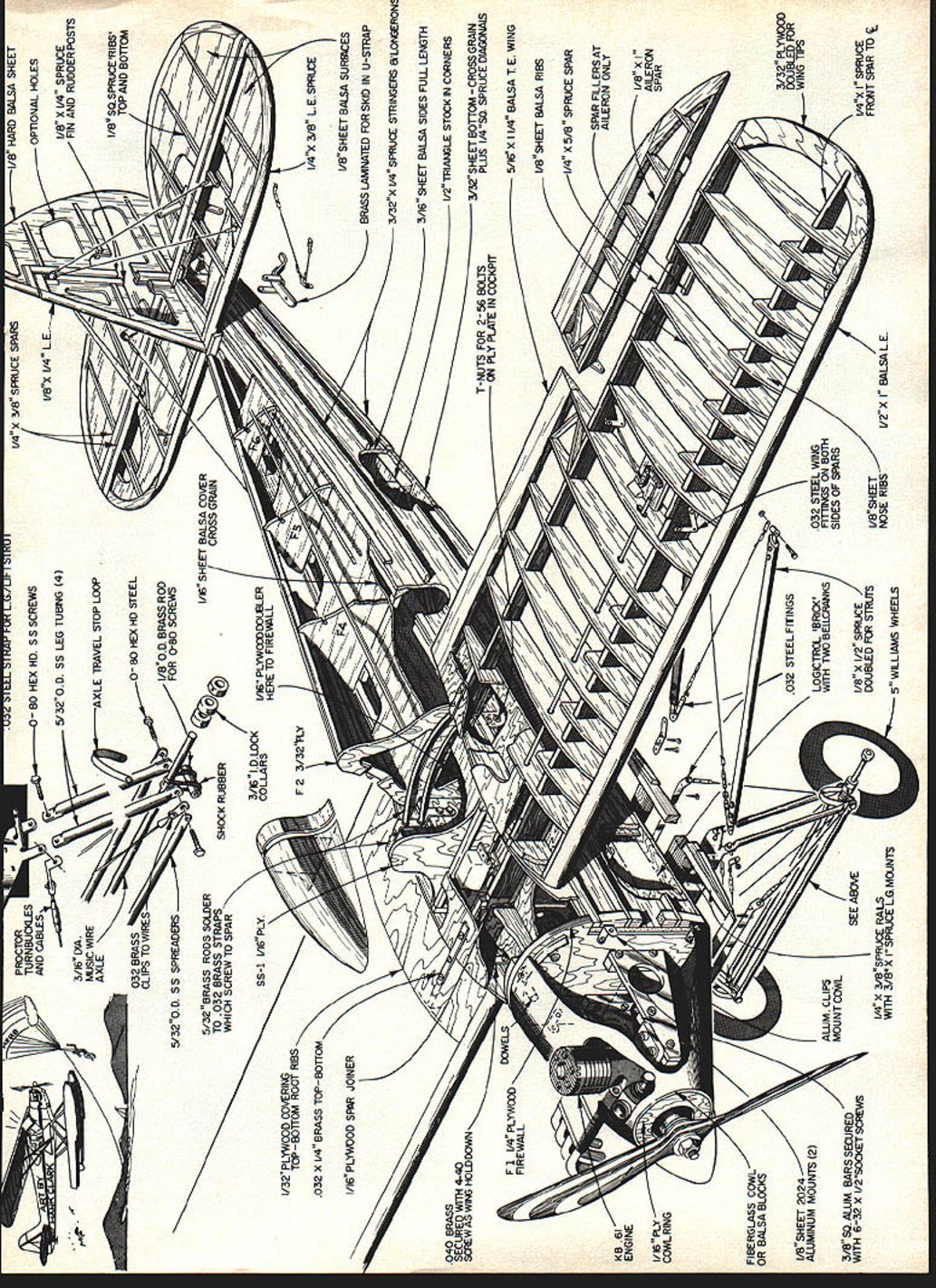
The fuselage construction is straightforward. The sides are 5/32 in. sheet balsa (if unavailable, slightly softer 3/16 in. may be used). After cutting formers F‑1 and F‑2, epoxy them into place and assemble. Install the 1/16 in. plywood floor and sheet the aft portion top and bottom before making landing‑gear and strut fittings.
Fittings are made from 1/32 x 2 x 18‑in. ground stock (tool steel) obtainable from machinist or mill supply houses. While there, buy 6‑32 socket‑head capscrews and necessary taps and drills. When cutting or drilling tool steel, avoid overheating; if it hardens, anneal by heating red hot and cooling slowly. After bolting fittings in place, install stringers as shown on the plans.
Landing gear: I found 5/32‑in. stainless steel tubing at a surplus store and made the landing gear much like the original — flattening the ends, drilling the flattened portions and bolting the assembly together. The front view on the plan shows the exact length (hole‑to‑hole measurement about 4 in.); remember the ends are 90° out of phase. Four legs are needed.
If you cannot get 5/32‑in. stainless tubing, options include:
- Use 5/32‑in. brass tubing and cut short lengths of 1/8‑in. music wire to fit inside between the flattened ends.
- Make the landing gear from 5/32‑in. music wire and bolt the wire across the fuselage to the 1/16 ply floor.
- Check surplus stores (as I did).
For fuselage fasteners, stainless steel 0‑80 hex head screws from Caltronics Laboratory worked well; I have not had one bolt break. Also pick up some 2024 aluminum (1/8 x 5 x 5 in. for motor mounts and 1/8 x 3/8 x 12 in. for the 3/8" square beams). The motor mount can be made with a hacksaw and file; locate holes for your engine on the beams, ensuring correct length from engine drive washer to firewall.
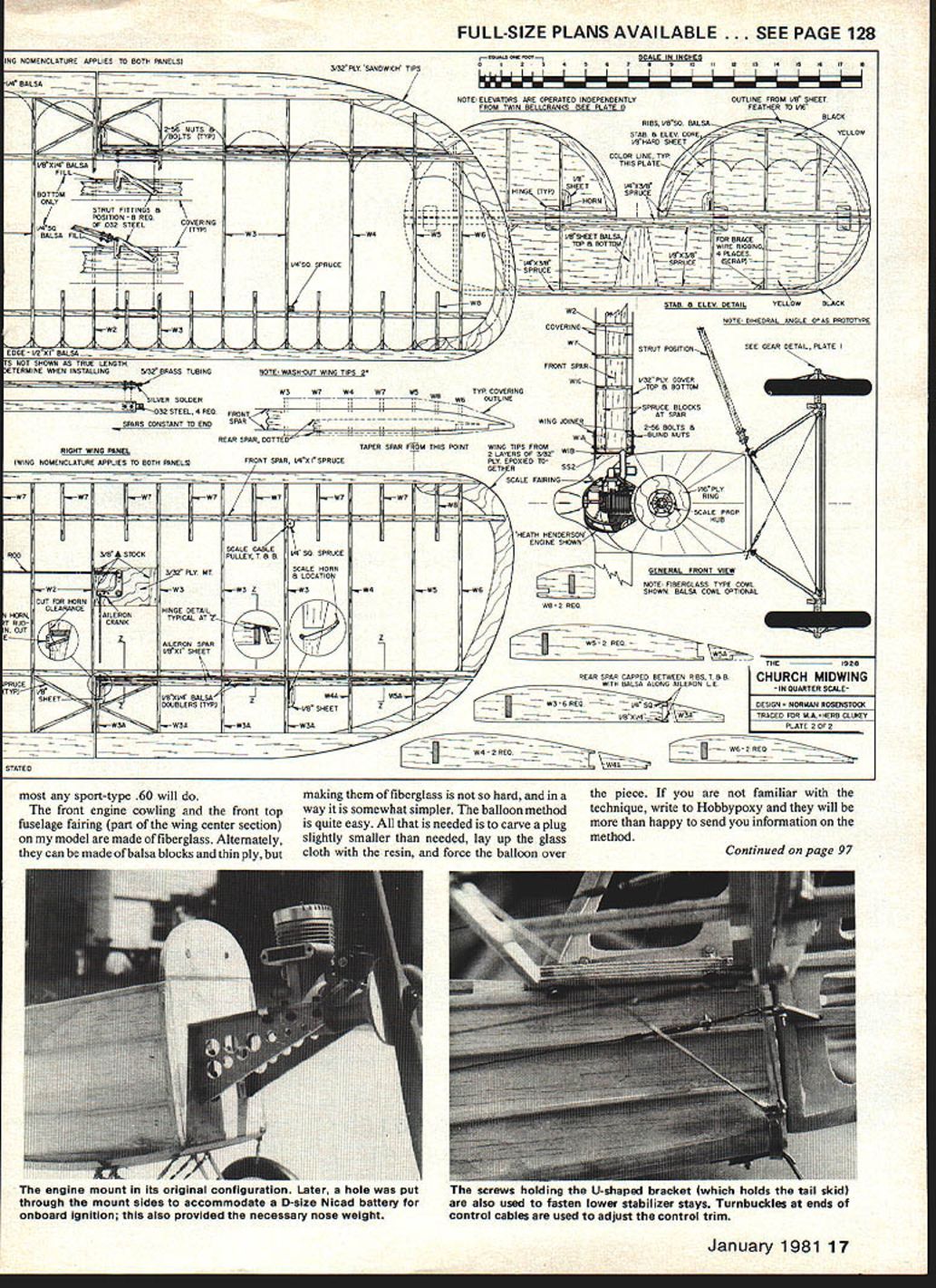
Front engine cowling and front top fuselage fairing (part of the wing center section) on my model are fiberglass. They can alternatively be built from balsa blocks and thin ply, but fiberglass using the balloon method is not hard: carve a slightly undersize plug, lay up the cloth and resin, then force a balloon over the piece. Hobbyopoxy can provide instructions.
My engine spinner is machined aluminum. For static judging it can be made from balsa and glued to a scale‑type prop; for flying you can substitute another spinner and prop as needed.
The radio installed was a brick unit (receiver + three servos) — convenient to install and remove.
Tail surfaces
- Construction: 1/8‑in. firm balsa with 1/16‑in. square ribs glued in place.
- Taper ribs and some sheet core with a large sanding block, leaving about 1/16‑in. thickness at the trailing edge. Sand the leading edge to a rounded cross‑section.
- Each elevator has its own horn and is hooked up with control cables (Proctor Enterprises) to a bellcrank in the cockpit floor. A short 1/16‑in. music‑wire pushrod connects the bellcrank to the elevator servo. The rudder uses the same arrangement with its bellcrank alongside the elevator bellcrank.
- The stabilizer is anti‑servo, built of 1/8‑in. sheet on the top longeron; the vertical fin is epoxied to the stabilizer. Take care with alignment; on my airplane the stab incidence is 0°.
- Control horns are made from .040 aluminum (three required). Roughen the portion glued inside the surface before epoxying.
I bolted the tail assembly together and onto the fuselage, though that method was labor‑intensive.
Wings
The wing is constructed conventionally. Wing tips are made from two layers of 3/32 in. ply: cut four pieces and epoxy them into two completed tips spanning leading edge to trailing edge. After assembling the wing and tips and allowing epoxy to cure, cut out the ailerons and separate the wing tip at that point.
Install servos in the wing root to avoid electrical extensions; use a "Y" connector to link the two aileron servos to the receiver.
- Spars: 1/4 x 1 in. spruce. If unavailable, epoxy two 3/16 x 3/8 in. pieces together. Do not use white glue unless you can clamp the spar over its entire length until fully cured — water in white glue can swell and warp the wood. I used slow‑cure epoxy and clamped to the edge of a workbench; in two hours I could proceed.
- Build the wing center section at the same time as the panels so the three pieces fit correctly. After SS‑5 assembly and installing brass wing joiner strips, roughly assemble the wing on a large bench to check fit. Butt ribs WIA and WIB should contact SS2 on the center section; note how brass strips overlie the spar.
- Instead of scaling the original 5/16 x 6‑in. thru‑bolts (which would require uncommon long screws), I glued filler blocks to the spar between the first two ribs and inserted blind 2‑56 nuts under the blocks to align with holes in the brass straps. In total, 16 2‑56 hex head screws fasten the wing to the center section. After epoxying spacer blocks, make a ply mount for the servo and provide a removable hatch on the bottom of the wing plate for servicing. Glue 1/32 ply in place. Do not cut off the spar projections at the root end; the spar should project 2 in. beyond the root rib.
- Wing spars should project as specified on plans; verify brass strap placement.
Wing support struts: The drawing shows struts but not exact length; on my model the wood portion was about 19 in. (excluding fittings). Make fittings from 1/32‑in. steel (four required). Cut four pieces of 1/8 x 1/2‑in. spruce a little longer than needed. Notch one strip, install a fitting with five‑minute epoxy or Hot Stuff, adjust the length and tack the other fitting, then epoxy. Drill #43 holes through the predrilled fitting into the wood, glue the second strip on top, and drill back through the holes into the second piece. Install short 2‑56 round‑head bolts and nuts with a little epoxy, sinking the head and nut slightly into the wood. Make two front and two rear struts; they differ in airfoil shape.
Rigging: The rigging on the wing support struts is criss‑crossed — from the rear fitting at the fuselage to the forward fitting at the wing and from the front fuselage connection to the rear wing fitting. I used two turnbuckles, one per wing, and safety‑wired them after adjustment. Fasten the strut fittings to the spars as shown on the wing drawing with 2‑56 round‑head screws and nuts and a little epoxy. Place 1/16‑in. balsa around the fittings to provide a place to hang the covering.
Covering and finishing
In my experience the Coverite covering used on this model is the best yet; it adds significant strength. The model was doped with clear butyrate dope and then sprayed with three to four coats of Cub yellow, trimmed with black as on the original.
Electrical / battery / ignition
- I installed a D‑size four ampere‑hour NiCad in the nose to help with tail‑heavy balance. Drill out the motor mount side plates and insert aluminum tubing large enough to carry the battery. Wrap the battery with foam rubber and provide foam padding in the tubing.
- The battery is switched to the glow plug and is engaged when the carburetor is between idle and one‑third open via a microswitch on the throttle linkage. This provides reliable idling down to about 1,800 rpm and eliminates the need for an external starter battery: open the throttle wide, flip the prop one or two times with the choke, then close to idle — usually starts on the first or second flip.
- Cautions: 1) Never run the engine in the plane when not on the ground or the battery will be drained quickly. 2) Ensure the tubing and foam padding properly secure the battery; without padding the battery can damage the tubing. A 1/8‑in. wheel collar with 18‑ or 20‑gauge wire soldered to it makes an excellent plug connector; use a cardboard washer under the collar to prevent shorting.
Flying
The original aircraft had no dihedral, and this model follows that. It flies like a full‑scale aircraft — coordinated rudder must be used in turns; otherwise turns look stilted.
My model weighed about 9½ lb., giving a wing loading of roughly 20 oz. per sq. ft. First takeoff: I added a little power to get rolling, then a bit more for rudder effectiveness, and the plane suddenly lifted off. The engine was turning about 7,000 rpm with a 13x6 Top Flite prop; the K&B .61 will give up to about 10,000 rpm on that prop. In flight it handles best when throttled back to about 8,000 rpm.
I considered a .45 engine but kept the .61 for extra power and nose weight (a smaller engine would require lead to maintain correct C/G). The ship floats over a hot runway like an old 40 hp Cub; to make a wheel landing feed in a little down to increase sink rate. The on‑board ignition/starting system helps because at very low rpm the prop acts as a disk, creating drag; the on‑board ignition keeps the engine running at low speeds.
Although the model was a lot of work, building it was very satisfying. Enjoy the project.
Sources
- Classic Models, P.O. Box 681, Melville, NY 11746. Documentation Booklet for Church Midwing, $3.00. Plans for 1½‑in. Church Midwing, $8.00.
- Experimental Aircraft Association, Inc., EAA Air Museum Foundation, Inc., Franklin, WI. 1931 Flying and Glider Manual, $2.00.
- Caltronics Laboratory, 461 S. Cochran Ave., P.O. Box 36356, Los Angeles, CA 90036. Catalog: precision model engineering and instrument components (stainless steel screws, etc.), no charge.
- Proctor Ent. Corp., P.O. Box 9641, San Diego, CA 92109. Turnbuckles, rigging and control cable, pulleys. Send for catalog, $1.00.
- Hobbyopoxy Products, 32 Pine St., Rockaway, NJ 07866. Instructions on balloon method of fiberglassing, no charge.
- Coverite, 420 Babylon Rd., Horsham, PA. Information on covering material; send pre‑addressed stamped envelope.
Transcribed from original scans by AI. Minor OCR errors may remain.

