
CIKLON 1
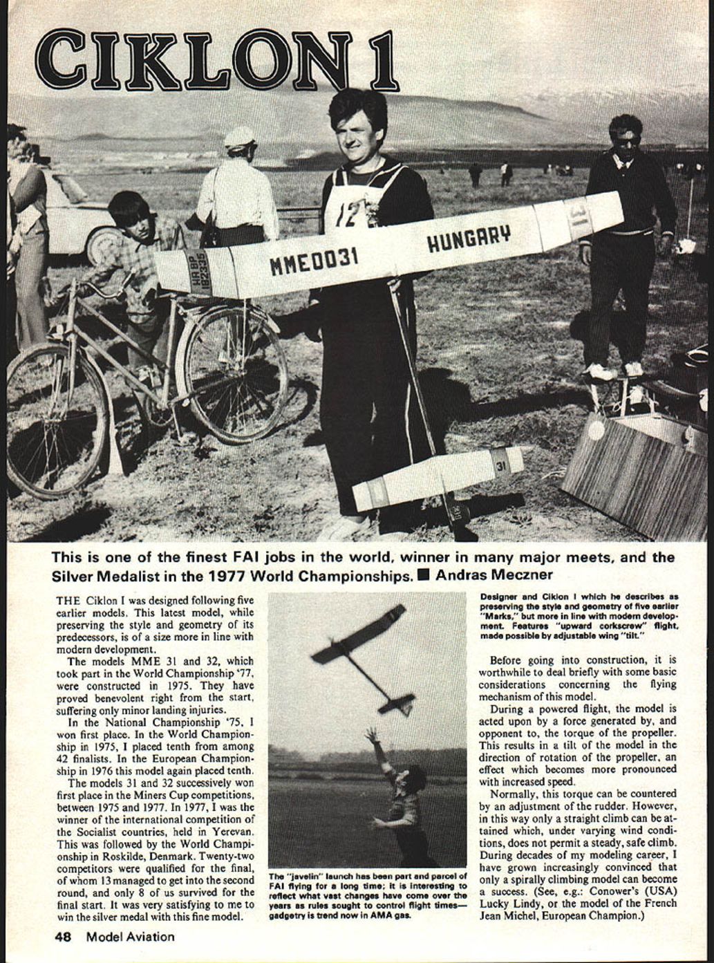
This is one of the finest FAI jobs in the world, winner in many major meets, and the silver medalist in the 1977 World Championships. — Andras Meczner
The Ciklon I was designed following five earlier models. This latest model, while preserving the style and geometry of its predecessors, is of a size more in line with modern development.
The models MME 31 and 32, which took part in the World Championship 1977, were constructed in 1975. They proved benevolent right from the start, suffering only minor landing injuries.
In the National Championship 1975 I won first place. In the World Championship in 1975 I placed tenth among 42 finalists. In the European Championship in 1976 this model again placed tenth.
The models 31 and 32 successively won first place in the Miners Cup competitions between 1975 and 1977. In 1977 I was the winner of the international competition of the Socialist countries, held in Yerevan. This was followed by the World Championship in Roskilde, Denmark. Twenty-two competitors were qualified for the final, of whom 13 managed to get into the second round, and only 8 of us survived for the final start. It was very satisfying to win the silver medal with this fine model.
Before going into construction, it is worthwhile to deal briefly with some basic considerations concerning the flying mechanism of this model.
During powered flight the model is acted upon by a force generated by, and opposing, the torque of the propeller. This results in a tilt of the model in the direction of rotation of the propeller; the effect becomes more pronounced with increased speed.
Normally this torque can be countered by an adjustment of the rudder. However, in this way only a straight climb can be attained, which under varying wind conditions does not permit a steady, safe climb. During decades of my modeling career I have grown increasingly convinced that only a spirally climbing model can become a success (see, e.g., Conower's Lucky Lindy, or the model of Jean Michel, European Champion).
Such upward corkscrew flight can be attained when the wings are tilted 15–20 degrees, i.e., the side toward which the propeller rotates is set at a greater angle of inclination to the horizontal. Unfortunately, the torque thus resulting can be very disadvantageous: the model becomes apt to turn over and finds it difficult to stabilize and come back into a normal glide. Ciklon I's adverse effect is completely offset in both powered and free flight by a special wing-moving mechanism. The adjustable relative position of the wings on the opposite sides can be changed by putting changeable washers under the M3 bolt (see drawing).
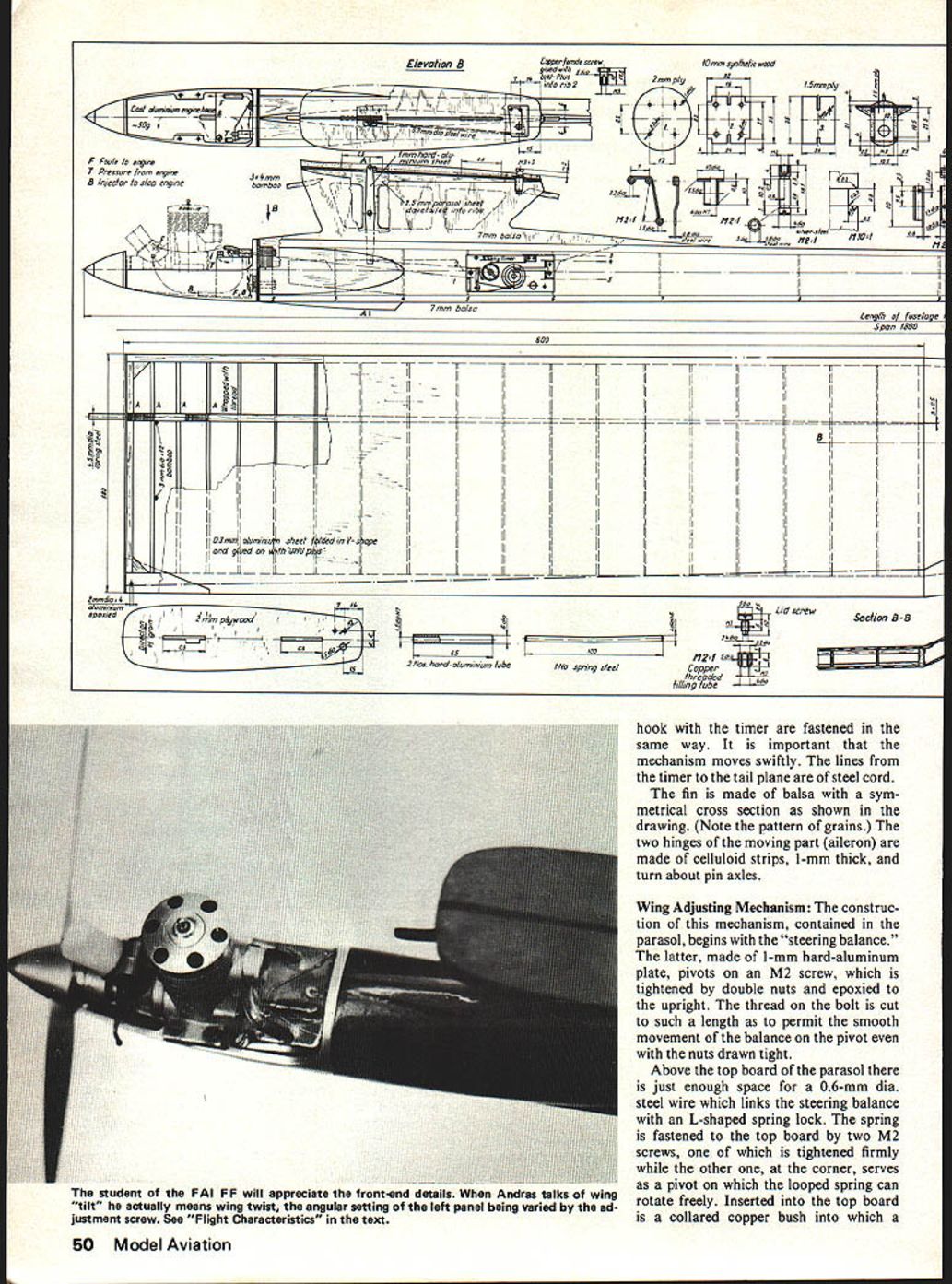
Another novel feature of the model is the engine-stopping device. I prefer a simple arrangement: silicone rubber pressed down by a steel spring. Simplicity, however, led to crash occasions; the needle-type shut-off valve used in Ciklon requires precision making and faultless operation over years. Special maintenance is well worth the extra effort. The principle of operation is as follows: the Seelig timer pulls back the needle valve into the closed position — no flow of fuel. As the timer releases the valve, fuel is allowed to pass to the engine. Immediate opening of the valve is aided by a torsion spring. One end of the torsion spring is threaded through the needle valve and formed into a hook connected via a steel actuating cord to the Seelig timer.
Vertical maneuverability is provided by two small M2-size control screws inserted under the tailplane at the fuselage. By this means the position angle of the tailplane can be set for the required powered flight and free glide. For powered flight both screws are clamped down. Hammer-head hooks hinged to the bottom of the fuselage actuate two separate coil springs. The left-hand hook serves free-glide control; the right-hand hook serves landing control.
When the left hook slips back, thus releasing the clamp screws, the hinged tailplane is allowed to tilt to the position required for free glide. When the right-hand clamp is released, the tailplane swings to a position inclined 40 degrees to the horizontal, required for landing. To facilitate tilting the tailplane to the desired position, a U-shaped steel spring anchored to the top board of the fuselage is used to limit the tilt of the tailplane to the 40 degrees required and also to prevent wear of the woodwork. A thin aluminium plate, cut and bent as shown in the drawing, is epoxied to the underside of the tailplane. A piece of wire hooked at both ends to the fuselage and threaded through a thin-walled steel tube, cotton-threaded and glued into the leading edge, serves as the hinge for the tailplane.
Fuselage
The two vertical sides are made of stiff 4-mm balsa reinforced by 4 x 4-mm spruce strips along the edges. Upon drying of the glue, both sides are reduced in thickness towards the tail, as are the spruce strips, to have a cross-sectional area of 4 x 4 mm in the front and 3 x 2 mm at the rear. This work is best done with a grinding disc.
Next, mount the would-be top of the fuselage. A balsa board 7-mm thick is laid on a level surface, and the two vertical sides, spaced at distances corresponding to the widths of ribs 1 and 2, are glued on.
Upon drying, make slots on the top board for jointing the parasol (wing support), making sure that its plane is strictly in line with the longitudinal axis of the model. Finally, grind down the top by hand to give it a curved surface as shown in sections A-A and B-B on the drawing. (The parasol will be mounted with the rest of the model — the structure with balsa cover is completed.) All subsequent work is done through the open belly of the model.
First, place home and glue the numbered fuselage ribs (see table in the drawing). The fuselage is tapered towards the rear with the two sides bevel-jointed to form an edged tail. The fin projects through a slot to the bottom of the fuselage. The tailplane control device is also housed inside the fuselage, whose sides are reinforced with 1-mm plywood at the axle and anchors of the moving mechanism.
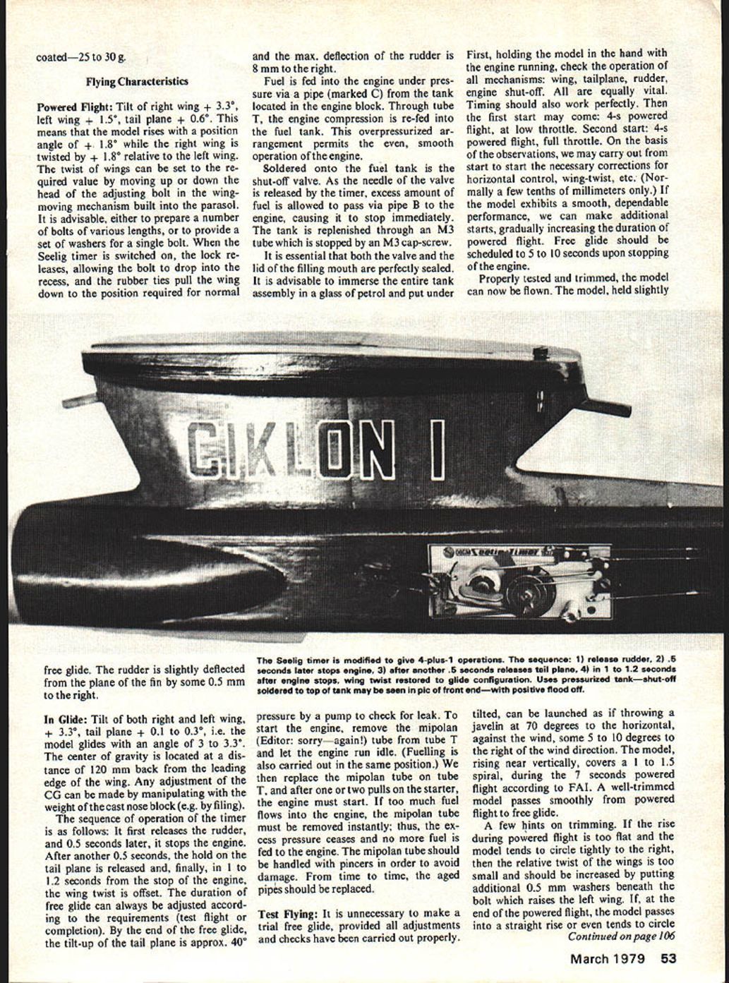
Maneuvering is controlled by a Seelig timer. The original device is slightly modified (4 + 1 operations) as shown in the picture and drawing. The timer device is fastened with an M2 screw to a hard aluminium plate. Since the width of the timer is 28 mm while that of the fuselage at this section is only 27 mm, a recess 0.5 to 0.7 mm wide and 2 mm deep should be made in the 4 x 4-mm spruce reinforcing strips to accommodate the timer (further details on drawing).
The two hammer-headed hooks used to hold down by the head the two M2 screws driven from below into the tailplane are made of 0.7 to 0.8-mm copper sheet, bent into U-shape, and placed at 5-mm centres as shown in the details. Connected to the hammer-head of the hook is a quick-release coil spring made of 0.4 to 0.5-mm steel wire coiled around a bolt, 2.2-mm dia. The far end of the spring is clasped about an axle, 1.2-mm dia. The spring is permanently tensioned by a force of 200 to 300 gf. The actuating lines which connect the lower part of the hammer-head hook with the timer are fastened in the same way. It is important that the mechanism moves swiftly. The lines from the timer to the tailplane are of steel cord.
The fin is made of balsa with a symmetrical cross section as shown in the drawing (note the pattern of grains). The two hinges of the moving part (aileron) are made of celluloid strips, 1-mm thick, and turn about pin axles.
Wing Adjusting Mechanism
The construction of this mechanism, contained in the parasol, begins with the "steering balance." The latter, made of 1-mm hard-aluminium plate, pivots on an M2 screw, which is tightened by double nuts and epoxied to the upright. The thread on the bolt is cut to such a length as to permit smooth movement of the balance on the pivot even with the nuts drawn tight.
Above the top board of the parasol there is just enough space for a 0.6-mm dia. steel wire which links the steering balance with an L-shaped spring lock. The spring is fastened to the top board by two M2 screws: one is tightened firmly while the other, at the corner, serves as a pivot on which the looped spring can rotate freely. Inserted into the top board is a collared copper bush into which a hook is fitted; the other end of the hook engages the looped spring so that the silver steel bolt can slip. It is important that the collared bush and the two screws are epoxied into place in this order.
In the power-flight position of the model, the spring lock is pulled in by a force of 300 to 500 gf so as to fit into the recess on the bolt and thereby hold it in a raised position. The bolt, with two grooves near the top and the bottom, is made of silver steel, 4 mm dia. The upper edge of the groove should be slightly rounded as shown on the details. On the upper part above the groove, the bolt is threaded inside to take an M3 screw, by means of which the magnitude of the wing tilt can be controlled. The device is very simple, but its construction requires precision and care. All wires in the mechanism are formed at the anchor end into a safety hook and simply hooked in. Before putting on the balsa cover, check that everything in the mechanism moves swiftly.
The sides of the parasol are made of 5-mm mirror-cut balsa with grain vertical.
Wings
The wings are covered on the top and bottom with 1.6-mm balsa. Construction is facilitated by a wooden template whose upper curved surface is identical with that of the underside of the wings.
First, make two main bearers using 3.5 x 6-mm spruce strips, laid flat and tapered towards the wing tip so as to have a reduced cross-section of 3.5 x 0.5 mm where the flap is attached. The flaps require no bearer.
To fasten the two wings together, a cotton-threaded hard-aluminium tube, 65 mm long by 6-mm dia., is epoxied between the main bearers in each wing. This work requires great care. The bores in the tubes are neatly ground and polished so that a spring-steel bolt 100 mm long, bent to secure the required dihedral, fits tightly.
The leading edge is made of a 3 x 6-mm spruce strip. There is no reinforcement at the trailing edge; only the bottom balsa sheet is bevelled and glued to the top sheet as shown in the drawing.
The flap, prepared separately, is attached to the mid-part; the joint is bevelled to give the obtuse angle required (a V-shaped template is convenient).
Apply some glue on the joint surface; after a while repeat it and fit the two parts together, fixing them temporarily by a pin. At the same time glue the 3-mm balsa rib at the joint into position. Then glue in the main girder followed by the balsa ribs in the order marked on the drawing. When the mid-part is complete, glue the reinforcing strip at the leading edge and then the ribs of the flap. The spruce strip, which is ground to the desired cross section beforehand, is bevel-jointed and glued to the leading edge strip of the mid-part.
The mid-part is provided with a 1.2-mm plywood rib at the inner end, while the wing tip is covered with a 5-mm balsa rib. The same template is used for mounting both the left- and the right-hand wings. A template having a common central part 70 cm long, onto which either the left or the right-hand side flap template can be bolted, has proven very useful.
The balsa sheet used for the bottom of the mid-piece of the wing is pinned to the template. The balsa sheet is cut about 10 mm wider at the leading edge and 3 mm wider at the trailing edge than the final dimensions. Stick a piece of adhesive tape under each rib on the template to prevent the ribs from being glued to it. The balsa sheet is made up of narrow strips butt-jointed and glued together on a flat surface to prevent warp. The balsa sheet is again oversized lengthwise by some 10 to 20 mm.
If using a slow-setting glue, the entire balsa cover may be jointed and glued in one go. The use of a celluloid glue may be more advantageous in order to minimize weight, but then one has to work fast. At the flap joint the balsa covers should be bevelled and glued right across on both the top and the bottom. This work is worth doing properly to ensure durability of the wings. The mounted wing must be left to dry on the template at least one or two days.
Upon removal, a few days' rest will be useful before the completed wing is trimmed to the final dimensions.
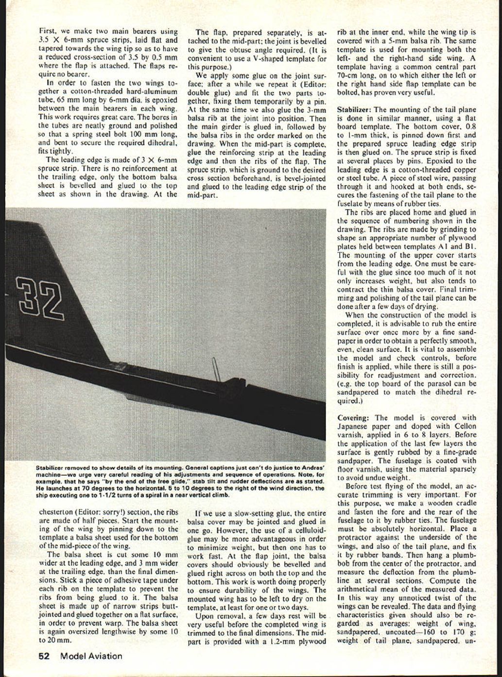
Stabilizer
The mounting of the tailplane is done in a similar manner, using a flat board template. The bottom cover, 0.8 to 1-mm thick, is pinned down first and the prepared spruce leading edge strip is then glued on. The spruce strip is fixed at several places by pins. Epoxied to the leading edge is a cotton-threaded copper or steel tube. A piece of steel wire, passing through it and hooked at both ends, secures the fastening of the tailplane to the fuselage by means of rubber ties.
The ribs are placed home and glued in the sequence of numbering shown in the drawing. The ribs are made by grinding to shape an appropriate number of plywood plates held between templates A1 and B1. The mounting of the upper cover starts from the leading edge. Be careful with the glue since too much of it not only increases weight, but also tends to contract the thin balsa cover. Final trimming and polishing of the tailplane can be done after a few days of drying.
When construction is completed, rub the entire surface once more with fine sandpaper to obtain a perfectly smooth, even, clean surface. It is vital to assemble the model and check controls before finish is applied, while there is still a possibility for readjustment and correction (for example, the top board of the parasol can be sandpapered to match the dihedral required).
Covering
The model is covered with Japanese paper and doped with Cellon varnish, applied in 6 to 8 layers. Before the last few layers are applied, the surface is gently rubbed with fine-grade sandpaper. The fuselage is coated with floor varnish, using the material sparingly to avoid undue weight.
Before test flying, accurate trimming is very important. For this purpose:
- Make a wooden cradle and fasten the fore and the rear of the fuselage to it by rubber ties. The fuselage must be absolutely horizontal.
- Place a protractor against the underside of the wings and also of the tailplane, and fix it by rubber bands.
- Hang a plumb-bob from the center of the protractor and measure the deflection from the plumbline at several sections.
- Compute the arithmetical mean of the measured data. In this way any unnoticed twist of the wings can be revealed.
The data and flying characteristics given should be regarded as averages:
- Weight of wing, sandpapered, uncoated — 160 to 170 g.
- Weight of tailplane, sandpapered, uncoated — 25 to 30 g.
Flying Characteristics
Powered Flight
- Tilt of right wing: +3.3°; left wing: +1.5°; tailplane: +0.6°.
- This means the model rises with a position angle of +1.8° while the right wing is twisted by +1.8° relative to the left wing.
- The twist of the wings can be set by moving up or down the head of the adjusting bolt in the wing-moving mechanism built into the parasol. It is advisable either to prepare a number of bolts of various lengths or to provide a set of washers for a single bolt.
- When the Seelig timer is switched on, the lock releases, allowing the bolt to drop into the recess, and the rubber ties pull the wing down to the position required for normal free glide.
- The rudder is slightly deflected from the plane of the fin by about 0.5 mm to the right.
In Glide
- Tilt of both right and left wing: +3.3°; tailplane: +0.1 to +0.3°.
- The model glides with an angle of 3 to 3.3°.
- The center of gravity is located at a distance of 120 mm back from the leading edge of the wing. Any adjustment of the CG can be made by manipulating the weight of the cast nose block (e.g. by filing).
Sequence of operation of the timer:
- It first releases the rudder.
- 0.5 seconds later it stops the engine.
- After another 0.5 seconds, the hold on the tailplane is released.
- Finally, in 1 to 1.2 seconds from the stop of the engine, the wing twist is offset.
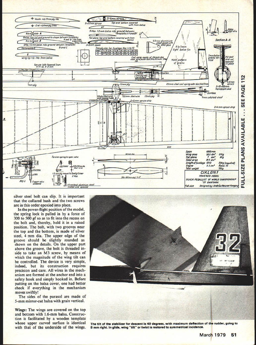
The duration of free glide can be adjusted according to requirements (test flight or completion). By the end of the free glide, the tilt-up of the tailplane is approximately 40° and the maximum deflection of the rudder is 8 mm to the right.
Fuel is fed into the engine under pressure via a pipe (marked C) from the tank located in the engine block. Through tube T the engine compression is re-fed into the fuel tank. This overpressurized arrangement permits the even, smooth operation of the engine.
Soldered onto the fuel tank is the shut-off valve. As the needle of the valve is released by the timer, excess fuel is allowed to pass via pipe B to the engine, causing it to stop immediately. The tank is replenished through an M3 tube which is stopped by an M3 cap-screw.
It is essential that both the valve and the lid of the filling mouth are perfectly sealed. It is advisable to immerse the entire tank assembly in a glass of petrol and put under pressure by a pump to check for leaks. To start the engine, remove the mipolan tube from tube T and let the engine run idle (fuelling is also carried out in the same position). Then replace the mipolan tube on tube T, and after one or two pulls on the starter the engine should start. If too much fuel flows into the engine, remove the mipolan tube instantly; thus the excess pressure ceases and no more fuel is fed to the engine. The mipolan tube should be handled with pincers to avoid damage. From time to time, aged pipes should be replaced.
Test Flying
It is unnecessary to make a trial free glide provided all adjustments and checks have been carried out properly.
- First, holding the model in the hand with the engine running, check the operation of all mechanisms: wing, tailplane, rudder, engine shut-off. All are equally vital. Timing should also work perfectly.
- First start: 4-s powered flight, at low throttle.
- Second start: 4-s powered flight, full throttle.
- Based on observations, carry out start-to-start corrections for horizontal control, wing-twist, etc. (Normally only a few tenths of millimetres.)
- If the model exhibits a smooth, dependable performance, make additional starts, gradually increasing the duration of powered flight. Free glide should be scheduled to 5 to 10 seconds after stopping the engine.
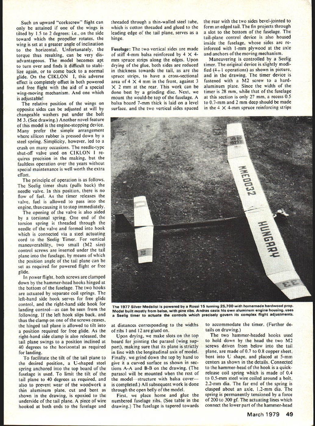
Properly tested and trimmed, the model can now be flown. Launch the model slightly tilted as if throwing a javelin at 70° to the horizontal, against the wind, some 5 to 10 degrees to the right of the wind direction. The model, rising near vertically, covers a 1 to 1.5-turn spiral during the 7-second powered flight according to FAI. A well-trimmed model passes smoothly from powered flight to free glide.
Hints on trimming:
- If the rise during powered flight is too flat and the model tends to circle tightly to the right, then the relative twist of the wings is too small and should be increased by putting additional 0.5-mm washers beneath the bolt which raises the left wing.
- If, at the end of the powered flight, the model passes into a straight rise or even tends to circle to the left, raise the left adjusting screw of the tailplane by 0.2 to 0.3 mm to increase the overall position angle.
- The timing of actuating the rudder might also be brought forward. If this does not help, try reducing the wing twist.
- Raise the right-hand adjusting screw of the tailplane, which controls free flight, to such an extent (i.e., increase the position angle) that the model glides safely even in gusts and in "thermic" weather conditions.
Transcribed from original scans by AI. Minor OCR errors may remain.

