
Circulator
Using the latest in construction materials and an ingenious circle-tow and timer-start system, this model is just waiting to take its place among the best of designs for the A-1 class of Towline Gliders.
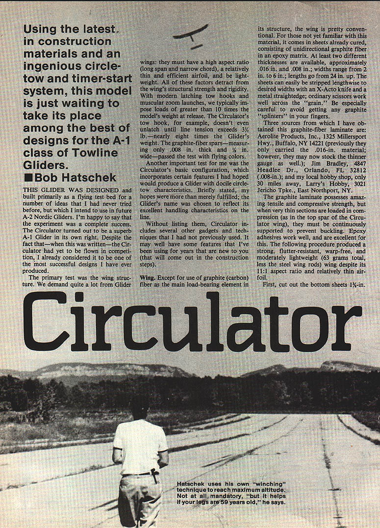
Bob Hatschek
This glider was designed and built primarily as a flying test bed for a number of ideas that I had never tried before, but which I intend to use in future A-2 Nordic Gliders. I'm happy to say that the experiment was a complete success. The Circulator turned out to be a superb A-1 glider in its own right. Despite the fact that — when this was written — the Circulator had yet to be flown in competition, I already considered it to be one of the most successful designs I have ever produced.
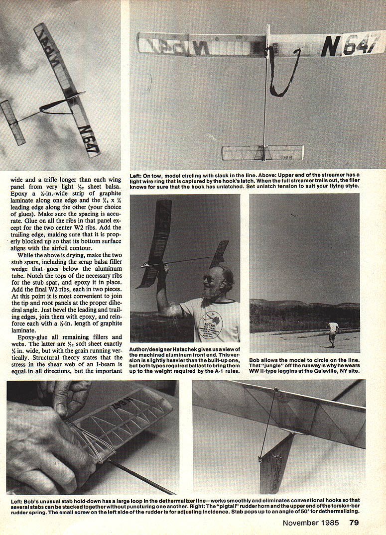
The primary test was the wing structure. We demand quite a lot from glider wings: they must have a high aspect ratio (long span and narrow chord), a relatively thin and efficient airfoil, and be lightweight. All of these factors detract from the wing's structural strength and rigidity. With modern latching tow hooks and muscular zoom launches, we typically impose loads of greater than 10 times the model's weight at release. The Circulator's tow hook, for example, doesn't even unlatch until line tension exceeds 3½ lb — nearly eight times the glider's weight. The graphite-fiber spars — measuring only .008 in. thick and 1/2 in. wide — passed the test with flying colors.
Another important test for me was the Circulator's basic configuration, which incorporates certain features I had hoped would produce a glider with docile circle-tow characteristics. Briefly stated, my hopes were more than merely fulfilled; the glider's name was chosen to reflect its excellent handling characteristics on the line.
Without listing them, Circulator includes several other gadgets and techniques that I had not previously used. It may well have some features that I've been using for years that are new to you (those will come out in the construction steps).
Wing
Except for the use of graphite (carbon) fiber as the main load-bearing element in its structure, the wing is pretty conventional. For those not yet familiar with this material, it comes in sheets already cured, consisting of unidirectional graphite fiber in an epoxy matrix. At least two different thicknesses are available, approximately .016 in. and .008 in.; widths range from 2 in. to 6 in.; lengths go from 24 in. up. The sheets can easily be stripped lengthwise to desired widths with an X-Acto knife and a metal straightedge; ordinary scissors work well across the "grain." Be especially careful to avoid getting any graphite "splinters" in your fingers.
Three sources from which I have obtained this graphite-fiber laminate are:
- Aerolite Products, Inc., 1325 Millersport Hwy., Buffalo, NY 14221 (previously the only source for the .016-in. material; they may now stock the thinner gauge as well).
- Jim Bradley, 4847 Headlee Dr., Orlando, FL 32812 (.008-in.).
- My local hobby shop: Larry's Hobby, 3021 Jericho Tpke., East Northport, NY.
The graphite laminate possesses amazing tensile and compressive strength, but when very thin sections are loaded in compression (as in the top spar of the Circulator wing), they must be continuously supported to prevent buckling. Epoxy adhesives work well, and are excellent for this. The following procedure produced a strong, flutter-resistant, warp-free, and moderately lightweight (63 grams total, less the steel wing rods) wing despite its 11:1 aspect ratio and relatively thin airfoil.
- First, cut out the bottom sheets 1 1/4 in. wide and a trifle longer than each wing panel from very light 1/32-in. sheet balsa.
- Epoxy a 1/2-in.-wide strip of graphite laminate along one edge and the 3/8 x 1/4 in. leading edge along the other (your choice of glues). Make sure the spacing is accurate.
- Glue on all the ribs in that panel except for the two center W2 ribs. Add the trailing edge, making sure that it is properly blocked up so that its bottom surface aligns with the airfoil contour.
- While the above is drying, make the two stub spars, including the scrap balsa filler wedge that goes below the aluminum tube. Notch the tops of the necessary ribs for the stub spar, and epoxy it in place.
- Add the final W2 ribs, each in two pieces. At this point it is most convenient to join the tip and root panels at the proper dihedral angle. Just bevel the leading and trailing edges, join them with epoxy, and reinforce each joint with a 1/2-in. length of graphite laminate.
- Epoxy-glue all remaining fillers and webs. The webs are 3/32-in. soft sheet exactly 1/4 in. wide, but with the grain running vertically. Structural theory states that the stress in the shear web of an I-beam is equal in all directions, but the important thing is to prevent buckling of the upper flange.
- A thorough epoxy top and a graphite spar can now be added; followed by beveling off the leading edge and adding the top sheet to complete the D-box. Alternately, the graphite can be epoxied to the top sheet to form a unit before applying the web. At least cover the bottom central area shown on the plans. A 2-in. sheet graphite strip should be epoxied dry into the first-bay filler.
- A short length of 1/32-in. aluminum tube has been glued into both wing-wire tubes; align carefully and apply epoxy. Set the filler in the rear tube. Add remaining fillers and top center-section sheeting.
Other details of wing construction are relatively straightforward and should present no difficulties.
Covering: Japanese tissue, five or six coats of thinned nitrate dope.
Stabilizer
Building the tail is simple; the adequately detailed drawing has been used in this structural design for 30 years and I recommend it highly. It is reasonably light, sufficiently strong and quite resistant to warps. Cover it again with Japanese tissue. Apply four coats of dope. The final weight of the original is six grams.
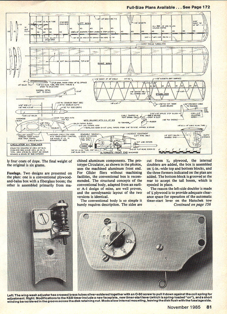
(Model Aviation full-size plans available. See Page 172.)
Fuselage
Two designs are presented on the plan: one is a conventional plywood-and-balsa box with a fiberglass boom; the other is assembled primarily from machined aluminum components. The prototype Circulator, as shown in the photos, uses the machined aluminum front end.
For glider fliers without machining facilities, the conventional box is recommended. The structural concepts of the conventional body, adapted from an earlier A-1 design of mine, are well proven, and the aerodynamic layout of the two versions is identical.
The conventional body is so simple it barely requires description. The sides are cut from 1/8-in. plywood; the internal doublers are added, the box is assembled on 1/2-in.-wide top and bottom blocks, and the three formers indicated on the plan are added. The bottom block is grooved at the rear to accept the tail boom, which is epoxied in place.
The reason the left-side doubler is made of 1/8-in. plywood is to provide adequate clearance space for operation of the automatic timer-start lever on the Hatschek tow hook.
Circulator / Hatschek hook
Instructions for the timer-start system are provided with the hook, which is available from:
- NFFS Supplies, 12 Cook St., Rowayton, CT 06853
- Or directly from R. L. Hatschek, 316 Grosvenor St., Douglaston, NY 11363
Price: $24 in the U.S.A. and Canada; $25 overseas.
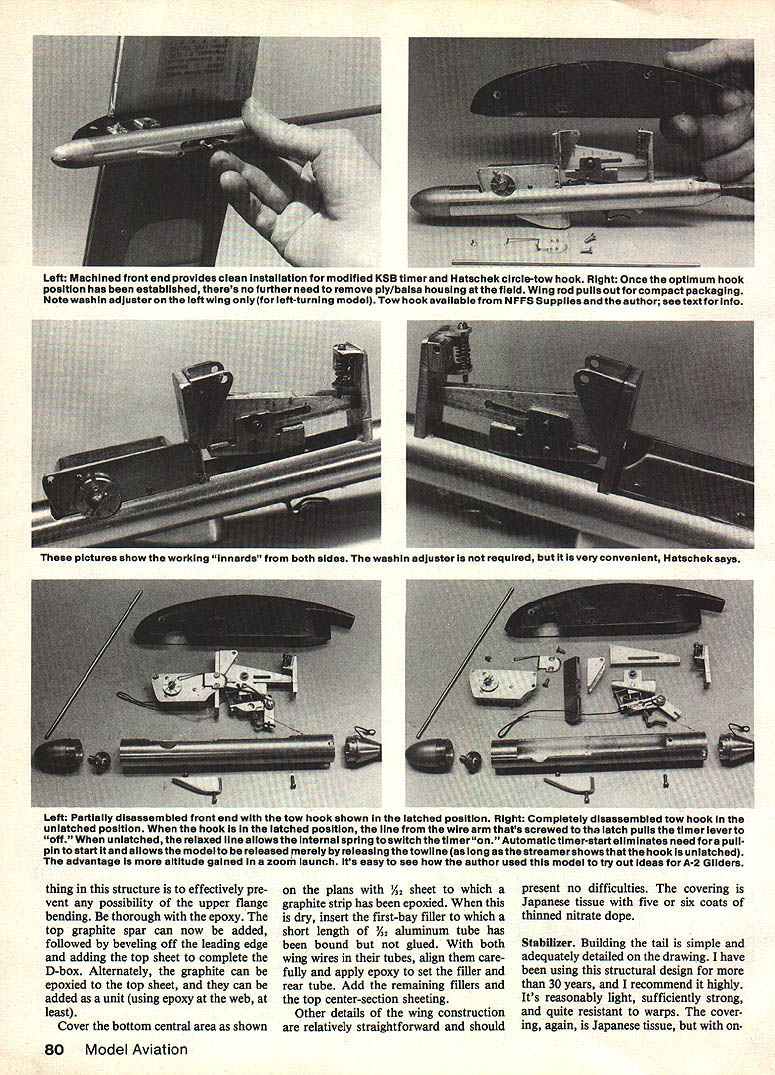
Obviously, you don't have to use a Hatschek hook. However, performance will be best with a full-function hook that includes a latch, separate rudder positions for straight tow, circle tow, zoom, and glide circle (all of which are independently adjustable), and an automatic timer start. I am not aware of any commercially available tow hook that provides all of these functions and is also compact enough to fit inside the Circulator fuselage.
A standard "pin-type" hook mount is used (see hook instructions). The mechanism is simply inserted through the top of the fuselage, and 1/16-in. music-wire pins are inserted through the holes in the body to secure the system. A series of holes allows the hook to be shifted to the optimum tow position. A simple hatch cover can be made from a piece of 1/16-in. sq. balsa profiled on the top to match the airfoil, inserted in the opening, and secured with the wing wires through it.
The tail boom of the original is what was left over from a fiberglass fishing-rod blank after the rest was used for an A-2 boom. Virtually anything similar would do, such as a fiberglass arrow shaft, but the weight should not exceed 12 grams — the lighter the better.
Remaining details are pretty straightforward and are shown either on the drawing or the photos.
Those glider fliers who are also machinists may prefer the alternate front end. Actually, the machined version offers no performance advantages; it just produces a more individualistic model, and I happen to enjoy working in metal. The all-wood version will probably be lighter, but it was still necessary to add seven grams of ballast at the center of gravity to bring the metal version up to the required 220 grams. (For anyone adding weight to a model with a two-piece plug-in wing, consider sheet brass or sheet lead ribs slipped over the wire root.)
The original Circulator body started as a length of 1/4-in. OD aluminum tubing with a wall thickness of .055 in. This was carefully turned down to .170 in. OD (.030-in. wall) to reduce weight. The remaining details should be pretty obvious from the plan and the photos for any machinist. All assembly screws are No. 2-56 (both flat head and fillister head) except for the trim screw in the nose, which is a round head 8-32. The thread holding the brass nose weight to the fuselage tube is 32 threads per inch with an OD of approximately .167 in.
The removable housing that hides all the machined parts consists of 1/2-in. plywood sides and 1/8-in.-wide balsa blocks and formers. This simply slips down over the 1/4-in.-wide aluminum formers and is held in place with the wing wires and the timer mounting screws. Doublers are not used.
Flight trimming
- Start at home by first positioning the tow hook as indicated in the drawings and then by adjusting ballast to put the center of gravity at 50% of the wing chord.
- Double-check both by simply hanging the completely assembled model upside down by its tow hook (any type) on a loop of string. The Circulator should dangle with its fuselage 15° from horizontal (tail down in the inverted position, of course). This is the simplest and most accurate way to check the correct positioning of a tow hook. The angle is much more important than the distance from the CG, but it's difficult to check outdoors in a breeze.
- Wing warps should also be checked at home. Correct by steaming, if necessary. Both tip panels should have equal washout of about 1/2 in. For a left-circling glider, the inboard panel of the right wing should be flat, and the inboard panel of the left wing should have about 1/8 in. of wash-in. For a right-circling glider, warps in the inboard panels should be reversed (and you should also have put the rudder horn on the left side, of course, and the incidence adjuster, if used, on the right).
- While still in the shop, check the tow hook action and clearances by setting the four rudder positions. Mine are as follows (back off 2–3 mm for initial flights):
- Straight-tow: 2 mm right
- Circle-tow: 6 mm left
- Zoom launch: 3 mm left
- Glide circle: 5 mm left
- At the field, initial hand glides (with the hook unlatched, so you have the glide-turn setting) should enable you to get the stab setting fairly quickly. I then start throwing the glider somewhat harder with the nose up and a slight left bank to simulate a zoom launch. You can tell quite a lot from this, but make sure you do it with the dethermalizer (DT) timer running!
- Make your first few trial tows with the hook unlatched until you're getting reasonably straight, safe tows. Then try a few with the hook unlatch tension set at about 2 lb. It will probably unlatch early, so progressively increase the setting by about 1/2 lb. at a time (you'll need a fisherman's spring scale). The original Circulator uses an unlatch setting of 3-1/2 lb. (My personal preference is for lighter settings than many other glider fliers; I "play" the model like a fish on a line to avoid premature unlatch.)
- When my left-circling Circulator comes overhead on a fairly zippy tow, it tends to turn slightly to the right (due, I believe, to the left-wing wash-in). Increasing tow speed at this point or slightly sooner unlatches the hook and gives slight left rudder, causing the turn and the bank to reverse. When the glider is banked slightly to the left — and this is a fairly critical bit of timing that takes practice to learn — I release it either by letting go of the line or by "plucking" it. Releasing the line gives a better zoom; plucking allows you to reel it in faster, since you don't have to chase the line first.
Additional insights into the enjoyment and competitive application of circle towing can be gleaned from the following sources:
- "Glider Flying — Russian Style," by Jim Wilson, Model Aviation, July 1978.
- "The Circle Game," by Gary T. Medley, Model Airplane News, December 1980 and January 1981 (two parts).
- "Ten Years at the Hook Works," by Bob Hatschek, NFFS Sympo Fourteen, August 1981.
Transcribed from original scans by AI. Minor OCR errors may remain.

