
CL Foam-Core Wings
Introduction
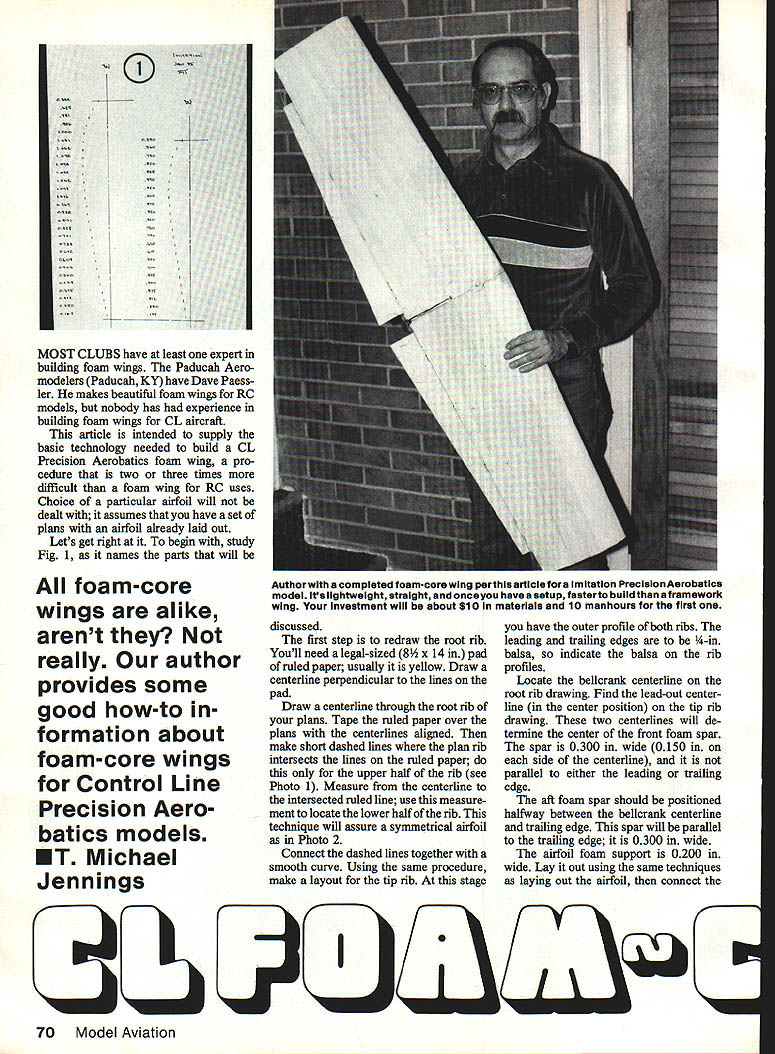
Most clubs have at least one expert in building foam wings. The Paducah Aeromodelers (Paducah, KY) have Dave Paessler. He makes beautiful foam wings for RC models, but few have had experience building foam wings for CL aircraft.
This article supplies the basic technology needed to build a CL Precision Aerobatics foam wing. The procedure is two to three times more difficult than building a foam wing for RC use. Choice of a particular airfoil is not covered; it assumes you have plans with an airfoil already laid out.
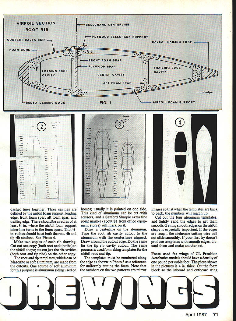
Study Fig. 1 (in the original) for the part names used below.
Redrawing Root and Tip Ribs
- Obtain a legal-sized (8-1/2 x 14 in.) pad of ruled paper (usually yellow). Draw a centerline perpendicular to the pad lines.
- Draw a centerline through the root rib on your plans. Tape the ruled paper over the plans with centerlines aligned.
- Make short dashed marks where the plan rib intersects the ruled lines — do this only for the upper half of the rib (see Photo 1 in the original).
- Measure from the centerline to each intersected ruled line; use these measurements to locate the lower half of the rib. This technique assures a symmetrical airfoil (see Photo 2).
- Connect the dashed lines smoothly. Repeat the procedure for the tip rib. You now have the outer profiles of both root and tip ribs.
- Indicate leading and trailing edges on the rib profiles — they are 1/4-in. balsa.
Layout: Spars, Bellcrank, and Foam Support
- Locate the bellcrank centerline on the root rib drawing.
- Find the lead-out centerline (in the center position) on the tip rib drawing.
- These two centerlines determine the center of the front foam spar.
- Front foam spar: 0.300 in. wide (0.150 in. on each side of the centerline); not parallel to L/E or T/E.
- Aft foam spar: positioned halfway between the bellcrank centerline and the trailing edge; parallel to the trailing edge; 0.300 in. wide.
- Airfoil foam support: 0.200 in. wide. Lay it out using the same dashed-line technique and connect to form smooth curves.
- There should be at least a 1/4-in. radius where the airfoil foam support inner line turns into the foam spars at both root and tip stations (see Photo 4).
Making Templates
- Make two copies of each rib drawing.
- On one copy, cut out the full airfoil shapes (root and tip).
- On the other copy, cut out just the rib cavities (root and tip).
- Use the rib-cavity cutouts to make templates from Masonite or soft aluminum (aluminum siding can work).
- Mark the aluminum with a Sanford Sharpie extra fine point marker.
- Draw a centerline on the aluminum; tape the rib cavity cutout to it with centerlines aligned and trace the outline.
- Number the airfoil root and tip templates along the edge (see Photo 5). Note the numbers on the two patterns are mirror images so templates back-to-back will match.
- Cut out four aluminum templates and lightly sand their edges until smooth. Smooth edges are critical for the nichrome cutting wire to slide cleanly. If edges are rough, remake the templates.
Foam Selection and Preparation
- Use foam with a density of about 2 pounds per cubic foot. The piece shown in the photos is 4 in. thick.
- Cut the foam block so the inboard and outboard wing halves are the correct length.
- Ensure the tip and root faces are perpendicular to the trailing-edge face.
- General procedure: cut the rib cavities first, then cut the airfoil shape.
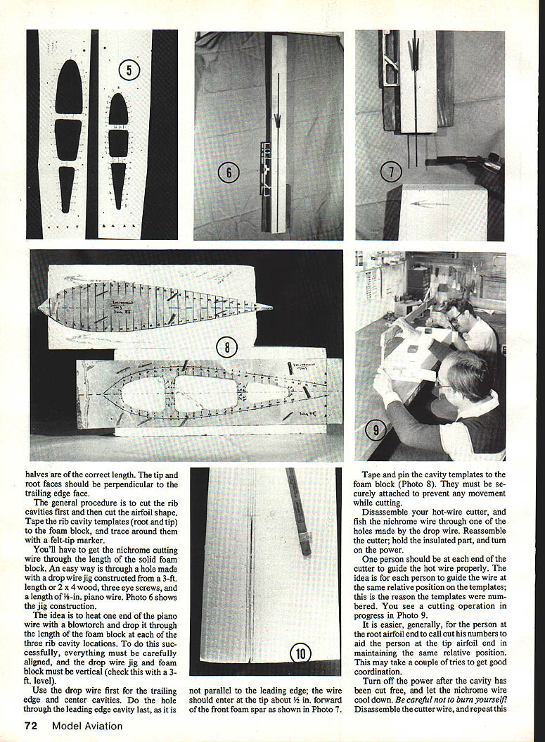
Getting the Hot Wire Through the Foam (Drop-Wire Jig)
- Construct a drop-wire jig from a 3-ft length of 2 x 4 with three eye screws along its length and a length of 1/8-in. piano wire.
- Use a blowtorch to heat one end of the piano wire and drop it through the length of the vertical foam block at each of the three rib-cavity locations (trailing edge center cavity first).
- Everything must be carefully aligned; the drop-wire jig and foam block must be vertical — check with a 3-ft level.
- Do the leading-edge cavity hole last because it is not parallel to the leading edge; the wire should enter at the tip about 1/2 in. forward of the front foam spar (see Photo 7).
Cutting Rib Cavities with Nichrome Hot Wire
- Tape and pin the cavity templates securely to the foam block (Photo 8).
- Disassemble your hot-wire cutter and fish the nichrome wire through one of the drop-wire holes. Reassemble the cutter, hold the insulated part, and turn on power.
- Two people are required — one at each end — to guide the hot wire so it follows corresponding numbered positions on the templates. The root person should call out their numbers to help the tip person maintain the same relative position. This may take practice (see Photo 9).
- Turn off the power after the cavity has been cut free and let the nichrome cool before touching it.
- Disassemble the cutter wire and repeat for the other two cavities.
- When finished, remove the cavity templates but leave the cavity cores in place.
Cutting the Airfoil Shape
- Tape and pin the airfoil templates in place. Align carefully so the airfoil foam support thickness will be 0.200 in.
- Cut the airfoil shape using the same numbered guiding method as for the cavities. When cutting is complete, remove the templates and slip out the cavity cores through the root end.
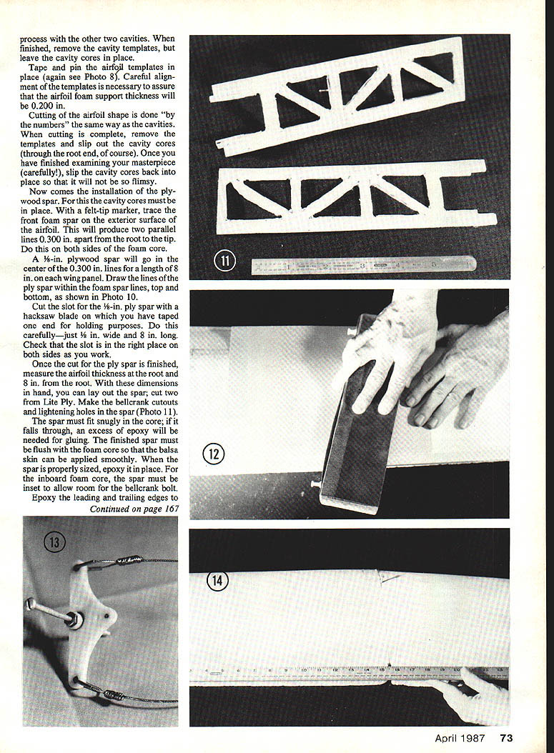
- Inspect the cores; then slip them back into place so the assembly remains supported for further work.
Installing the Plywood Spar
- With the cavity cores in place, trace the front foam spar location on the exterior of the airfoil to produce two parallel lines 0.300 in. apart from root to tip (do this on both sides).
- A 1/8-in. plywood spar will occupy the center of those 0.300-in. lines for a length of 8 in. on each wing panel. Draw the spar lines inside the foam-spar lines on both top and bottom (see Photo 10).
- Cut the 1/8-in.-wide slot with a hacksaw blade (tape one end for holding). The slot must be exactly 1/8 in. wide and 8 in. long; check alignment on both sides as you work.
- Measure airfoil thickness at root and at 8 in. from the root to size the spar. Cut two spars from Lite Ply, make the bellcrank cutouts and lightening holes (Photo 11).
- The spar must fit snugly; if it falls through you'll need excess epoxy. The finished spar should be flush with the foam core so the balsa skin lays smoothly.
- Epoxy the spar in place. For the inboard foam core, inset the spar to allow room for the bellcrank bolt.
Leading and Trailing Edges
- Leading edge: 1/4 x 3/4-in. balsa strip.
- Trailing edge: 1/4 x 1/4 in. balsa strip. Mark the centerline on the 1/4-in. side of the trailing edge to locate the flap hinge line and cut each hinge slot.
- Glue the leading and trailing edge strips with thinly spread epoxy. Hold strips in place with tape while epoxy sets.
Sanding:
- Sand L/E and T/E to the correct shape. There must be a smooth transition from foam core to trailing edge because the balsa skin will overlap it.
- To sand balsa without sanding foam, tape lightweight cardboard (notebook divider) over the foam butted to the balsa, then block-sand (Photo 12). Replace cardboard as needed. Remove cardboard and carefully sand until balsa is smooth with the foam.
- If the skin will overlap the leading edge, sand the L/E similarly or glue and sand the L/E after skinning.
Preparatory sanding:
- Lightly block-sand the foam core to remove ridges only. The foam is thin and fragile. Vacuum the sanded core carefully.
Skinning the Wing
- Use 1/16-sheet contest (lightweight) balsa for the skin. Edge-glue enough sheets to cover one side.
- Mix enough 45-min epoxy to cover two skins.
- Apply epoxy to the skin and use a playing card to spread and remove excess. The skin should be only damp with epoxy — avoid excess, which adds weight but not strength.
- Lightly coat the trailing-edge, leading-edge overlap, and plywood spar edge — again, remove excess epoxy.
- Apply skins with cavity cores in place for added rigidity. Start at the leading edge and roll the skin over the core (same method if using contact cement).
- Repeat for the other side. Place the subassembly back into the outer core saddles. When sandwiched together, add weights to compress everything while epoxy cures.
Bellcrank Assembly and Lead-Outs
- Make the bellcrank assembly with lead-outs. Bush the lead-outs with 1/16-in. brass tubing through the bellcrank.
- Slip the lead-out through a 1-1/2-in. length of tubing, slide the tubing through the bellcrank, and bend the tubing in a smooth radius.
- Make lead-out cable connections according to the AMA rule book (see Photo 13).
- Assemble the bellcrank. Secure the pushrod to the bellcrank so it does not interfere with movement.
- Notch the inboard wing for the bellcrank support and pushrod exit. The pushrod should have no bends between flap horn and bellcrank; this may require a larger exit notch than normal.
- Epoxy the bellcrank assembly into the inboard wing. Ensure smooth operation before proceeding.
Joining Wing Halves
- Both wing halves are ready to epoxy together while in the outer core saddles for alignment and support.
- At both inboard edges, trim away excess balsa skin. The foam cores should be square and not sanded. Remove the cavity covers.
- Lightly coat the foam cores and balsa-skin inboard edges with 45-min epoxy.
- Position the two edges together in the core saddles. Ensure trailing edges are straight and aligned (Photo 14). Allow epoxy to set.
- Cut two 3/8 x 1 x 1-in. plywood bellcrank supports, drill through their centers, and epoxy them to the wing skins. This reinforces the bellcrank area for high pull loads (e.g., 40-lb. pull tests).
Tip Joint Reinforcement
- Reinforce the wing tip butt joint with 1-1/2-in. strips of fiberglass. Lay down the fiberglass and brush epoxy through it. Remove excess epoxy with a playing card to keep weight down.
Weight, Time, and Notes
- Weigh the completed wing. For competitive Precision Aerobatics it should not exceed about 8 oz. If it is too heavy, consider non-competition uses. The most likely cause of excess weight is using 1/16-in. balsa that is heavier than the lightweight contest variety.
- Estimated materials cost: about $10. Estimated time: about 10 man-hours for the first wing (templates take about half the time); subsequent wings of the same design can be completed in about five hours.
- Advantages: foam-core wings are generally easier, faster, and straighter than built-up wings.
- Note: Installing wing tips and flaps is not covered in this article.
Acknowledgments
My thanks to Bob Vogel, good friend and photographic hobbyist, for the pictures used with this article.
Transcribed from original scans by AI. Minor OCR errors may remain.

