
Classic 320
This is a bit of a fairy tale with (I think) a happy ending. Once upon a time, long, long ago, there was only Free Flight, and all the models flew truly free—free of lines and radios and auto surfaces. Then along came radios and control lines, but the Free Flight models still flew free. (Try saying "Free Flight models still flew free" three times quickly!)
That is, until the advent of auto surfaces. Then the models' flight paths (at least under power) were preprogrammed. Combine the high-tech complexities of prop brakes and geared propellers and auto surfaces and electronic timers with the availability of custom-built, "store-bought" models, and you have the modern Fédération Aéronautique Internationale (FAI) Power events, all of which have been major contributing factors to the drop-off of participation in the FAI events. As some of these "advances" became more prevalent in the AMA events, a comparable decrease in participation became evident.
The decreased participation in FAI and AMA events was virtually concurrent with the growth of the Nostalgia and Old-Timer categories. There was a discernible pattern: complex and expensive models equal less participation; simple and inexpensive models equal more participation! The message got through to AMA's Free Flight Contest Board (FFCB). Effective in 2002, it approved and implemented the new (really old) Classic Power events. The ban on auto surfaces in these events, coupled with AMA's long-standing Builder-of-the-Model rule, should encourage a resurgence of interest and participation in the AMA Free Flight Power events. That's the happy ending to this fairy tale. A hearty "thank you" to the board members for unanimously approving the event rules and particularly to FFCB member Jim Bocchinfuso, who lobbied so diligently for their passage. Thanks also to board member Russ Snyder, who devised the original rules, to National Free Flight Society President Bob Stalick, who formally proposed them, and to Charlie Caton, whose modifying cross-proposal gave us our new Classic Power events.
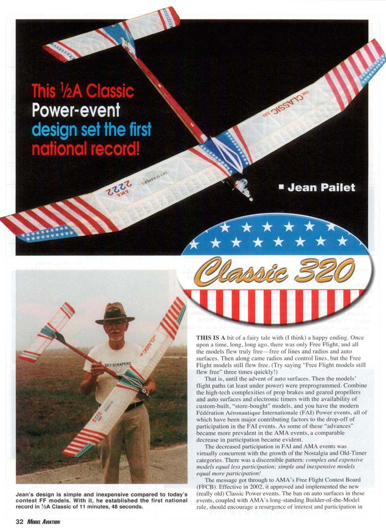
All of this brings us to the 1/2A power model depicted here: the Classic 320. Among the dictionary definitions of classic are "standard," "established," "traditional," "enduring," and "simple." At least two of those were guiding principles in this model's design; its format is traditional, and its construction is simple. The only "exotic" materials or parts used are the readily available carbon-fiber (CF) rods incorporated into the fuselage, wing, and stabilizer structures. There are no Kevlar or carbon D-boxes, no aluminum-carbon-aluminum fuse tubes, and no multifunction timers and tail fittings. Virtually all-balsa construction is used, and Polyspan is the covering material of (my) choice. In large part, the design is based on the predecessor Genie, Genie II, and Soarcerer models. Let's build a Classic 320.
CONSTRUCTION
Wing
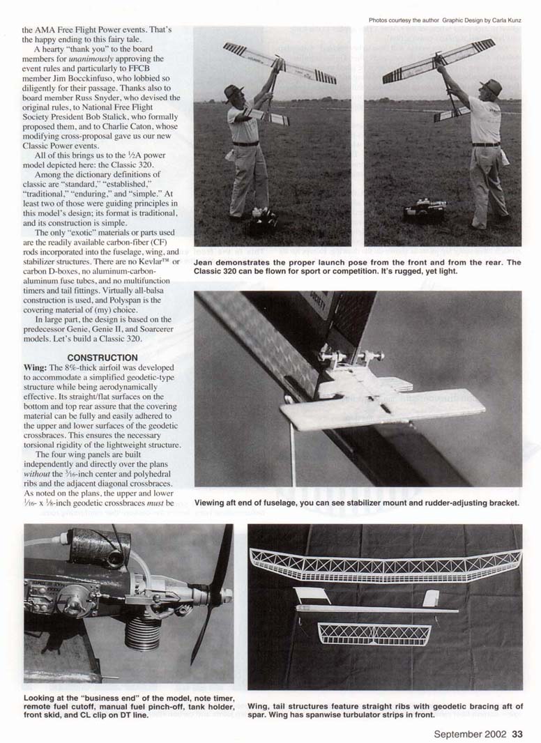
The 8%-thick airfoil was developed to accommodate a simplified geodetic-type structure while being aerodynamically effective. Its straight/flat surfaces on the bottom and top rear assure that the covering material can be fully and easily adhered to the upper and lower surfaces of the geodetic crossbraces. This ensures the necessary torsional rigidity of the lightweight structure.
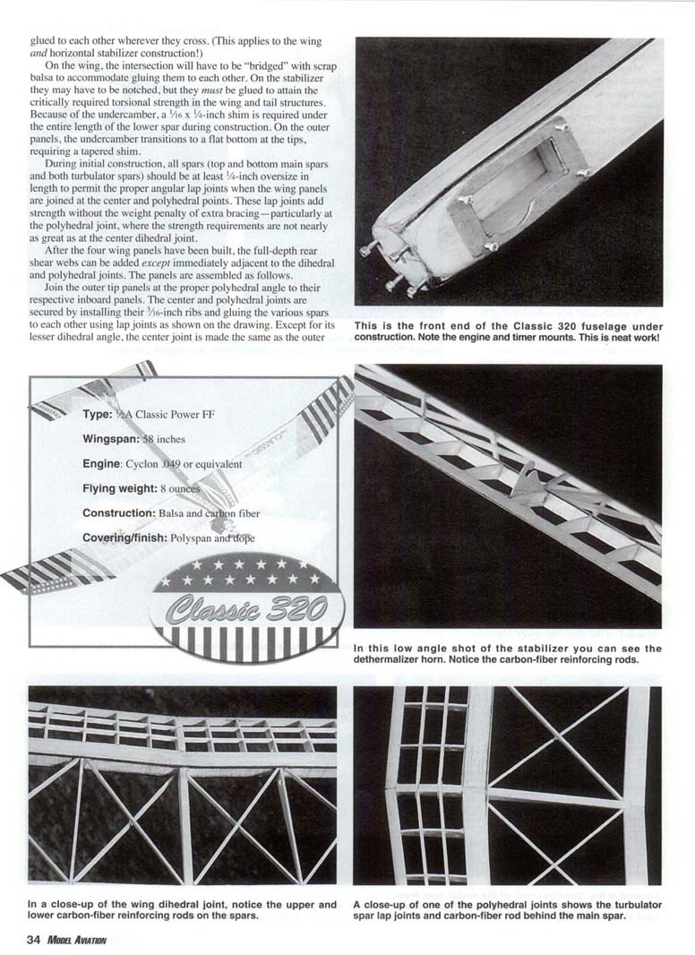
The four wing panels are built independently and directly over the plans without the 1/16-inch center and polyhedral ribs and the adjacent diagonal crossbraces. As noted on the plans, the upper and lower 1/16 x 1/8-inch geodetic crossbraces must be butted to the spar caps and glued to each other wherever they cross. (This applies to the wing and horizontal stabilizer construction.)
On the wing, the intersections will have to be "bridged" with scrap balsa to accommodate gluing the crossbraces to each other. On the stabilizer they may have to be notched, but they must be glued to attain the critically required torsional strength in the wing and tail structures. Because of the undercamber, a 1/16 x 1/4-inch shim is required under the entire length of the lower spar during construction. On the outer panels, the undercamber transitions to a flat bottom at the tips, requiring a tapered shim.
During initial construction, all spars (top and bottom main spars and both turbulator spars) should be at least 1/4 inch oversize in length to permit the proper angular lap joints when the wing panels are joined at the center and polyhedral points. These lap joints add strength without the weight penalty of extra bracing—particularly at the polyhedral joint, where the strength requirements are not nearly as great as at the center dihedral joint.
After the four wing panels have been built, the full-depth rear shear webs can be added except immediately adjacent to the dihedral and polyhedral joints. The panels are assembled as follows. Join the outer tip panels at the proper polyhedral angle to their respective inboard panels. The center and polyhedral joints are secured by installing their 3/16-inch ribs and gluing the various spars to each other using lap joints as shown on the drawing. Except for its lesser dihedral angle, the center joint is made the same as the outer joint.
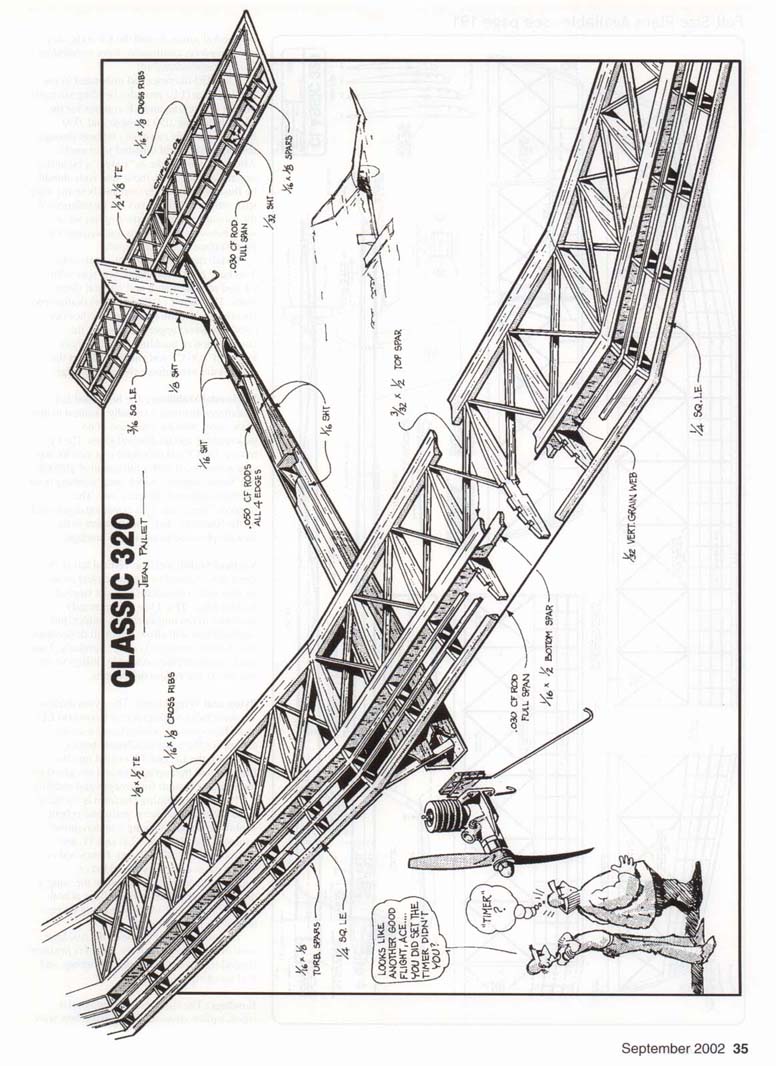
CLASSIC 320 — Jean Paulet
- .020" CF rods, full span, all 4 panels
- 1/8" square leading edge
- 3/32" x 1/8" top spar
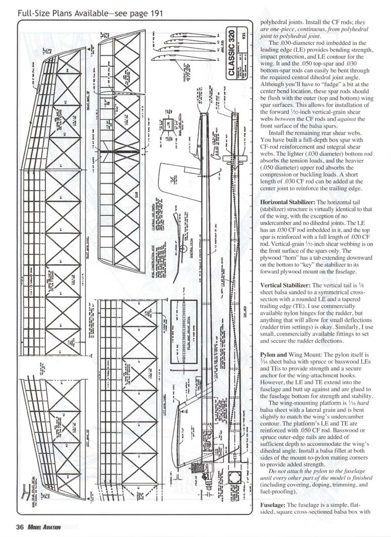
- Polyhedral joints: install the CF rods; they are one-piece, continuous, from polyhedral joint to polyhedral joint.
The .030-diameter rod imbedded in the leading edge (LE) provides bending strength, impact protection, and LE contour for the wing. It and the .050 top-spar and .030 bottom-spar rods can easily be bent through the required central dihedral joint angle. Although you'll have to "fudge" a bit at the center bend location, these spar rods should be flush with the outer (top and bottom) wing spar surfaces. This allows for installation of the forward 1/2-inch vertical-grain shear webs between the CF rods and against the front surface of the balsa spars.
Install the remaining rear shear webs.
You have built a full-depth box spar with CF-rod reinforcement and integral shear webs. The lighter (.030-inch diameter) bottom rod absorbs the tension loads, and the heavier (.050-inch diameter) upper rod absorbs the compression or buckling loads. A short length of .030 CF rod can be added at the center joint to reinforce the trailing edge.
Horizontal Stabilizer
The horizontal tail (stabilizer) structure is virtually identical to that of the wing, with the exception of no undercamber and no dihedral joints. The LE has a .030 CF rod imbedded in it, and the top spar is reinforced with a full length of .020 CF rod. Vertical-grain 1/32-inch shear webbing is on the front surface of the spars only. The plywood "horn" has a tab extending downward on the bottom to "key" the stabilizer to its forward plywood mount on the fuselage.
Vertical Stabilizer
The vertical tail is 1/8-inch sheet balsa sanded to a symmetrical cross section with a rounded LE and a tapered trailing edge (TE). I use commercially available nylon hinges for the rudder, but anything that will allow for small deflections (rudder trim settings) is okay. Similarly, I use small, commercially available fittings to set and secure the rudder deflections.
Pylon and Wing Mount
The pylon itself is 3/16-inch sheet balsa with spruce or basswood LEs and TEs to provide strength and a secure anchor for the wing-attachment hooks. The LE and TE extend into the fuselage and butt up against and are glued to the fuselage bottom for strength and stability.
The wing-mounting platform is 1/8-inch hard balsa sheet with a lateral grain and is bent slightly to match the wing's undercamber contour. The platform's LE and TE are reinforced with .050 CF rod. Basswood or spruce outer-edge rails are added of sufficient depth to accommodate the wing's dihedral angle. Install a balsa fillet at both sides of the mount-to-pylon mating corners to provide added strength.
Do not attach the pylon to the fuselage until every other part of the model is finished (including covering, doping, trimming, and fuel-proofing).
Fuselage
The fuselage is a simple, flat-sided, square cross-section balsa box with plywood doublers at the wing and pylon mounting points.
Transcribed from original scans by AI. Minor OCR errors may remain.

