
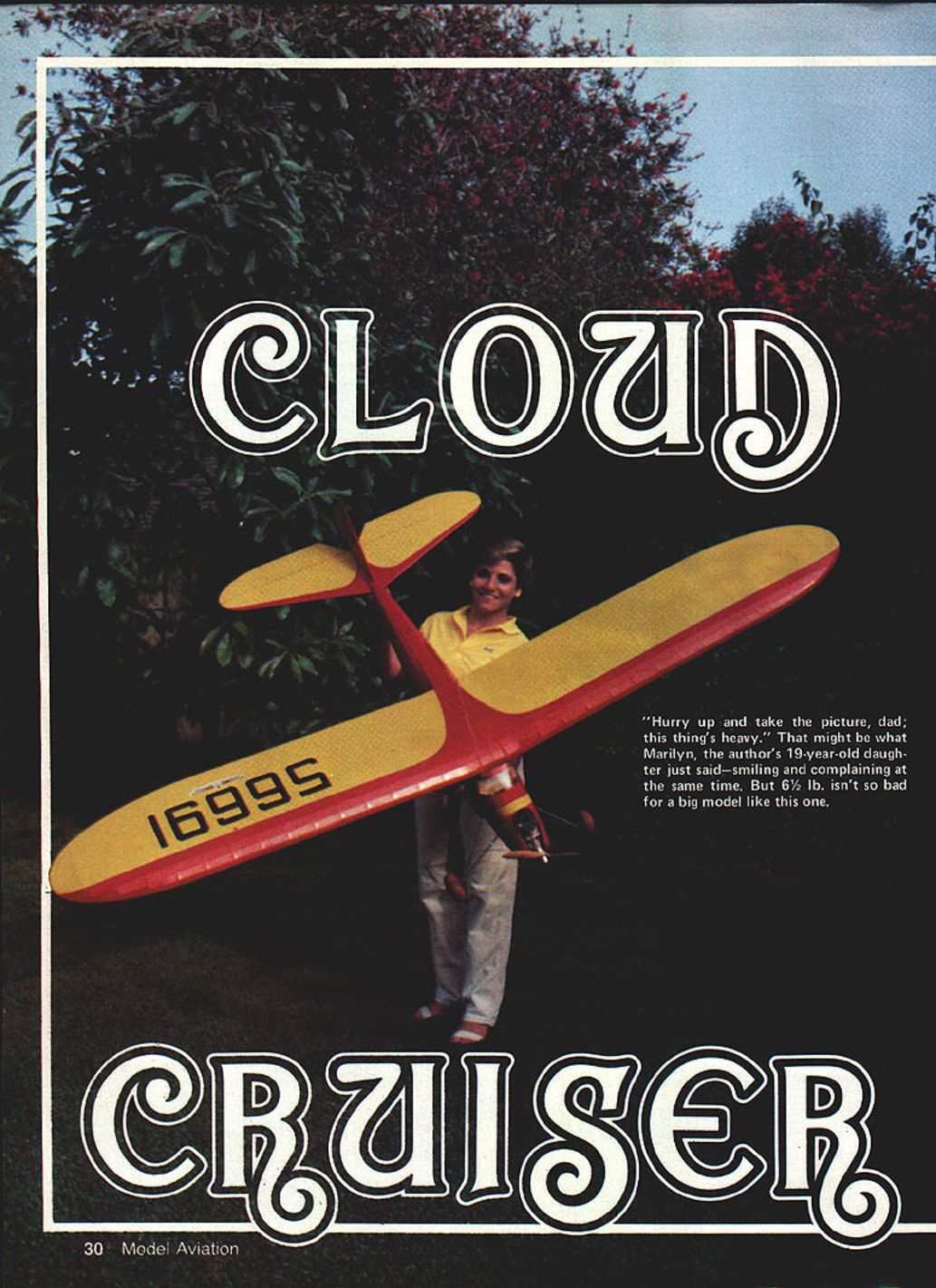
Cloud Cruiser
By Bob Oslan
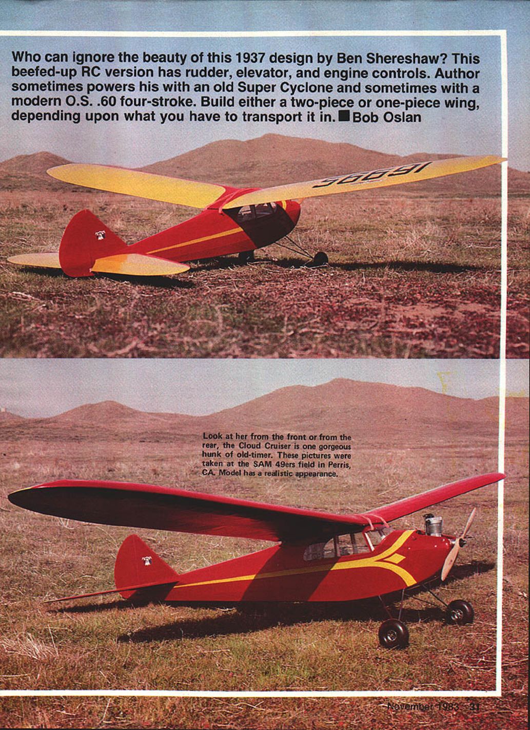
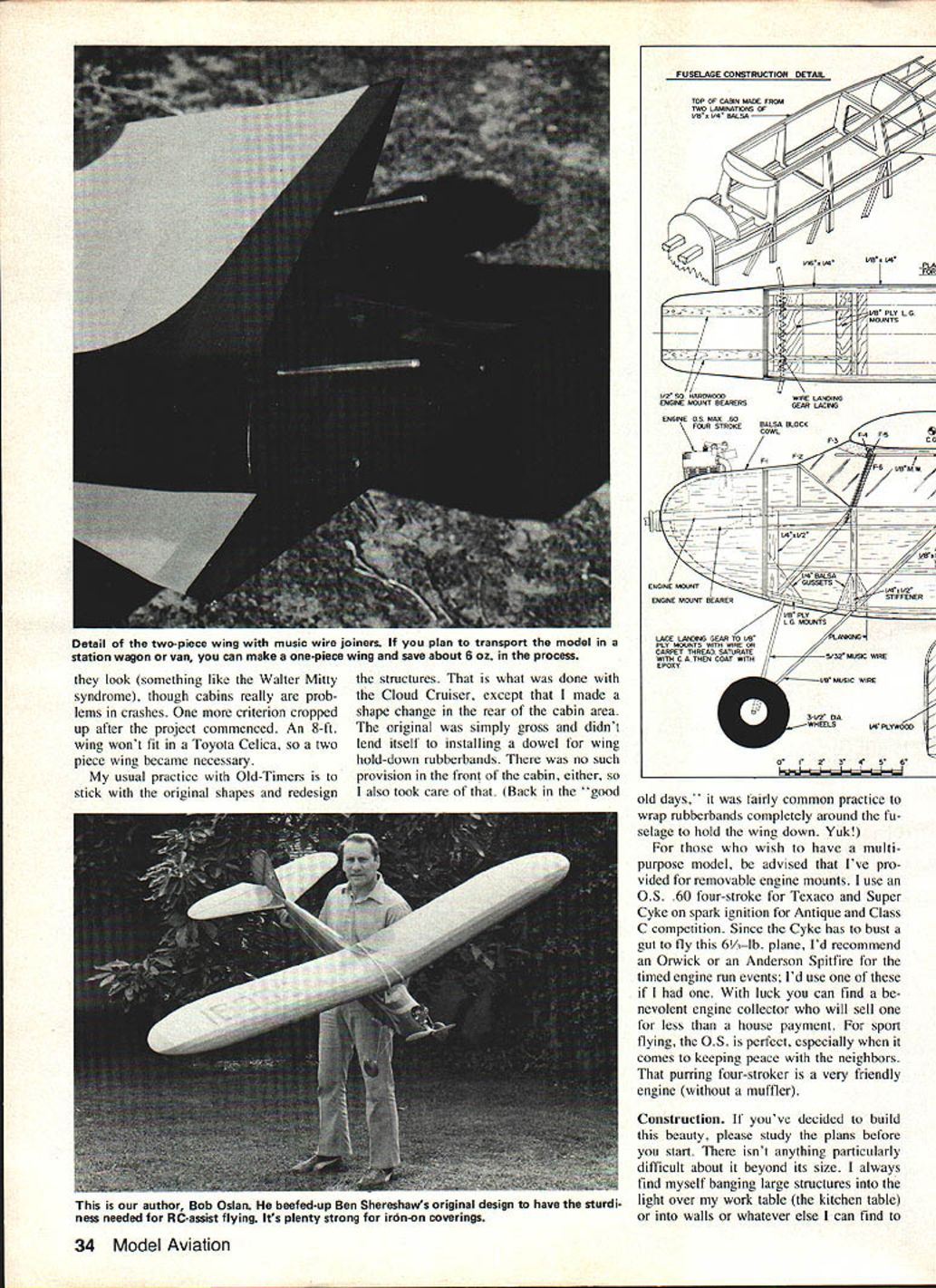
Who can ignore the beauty of this 1937 design by Ben Shereshaw? This beefed-up RC version has rudder, elevator, and engine controls. The author sometimes powers his with an old Super Cyclone and sometimes with a modern O.S. .60 four-stroke. Build either a two-piece or one-piece wing, depending on what you have to transport it in.
FROM SEPTEMBER 1937 to June 1939, Ben Shereshaw had 10 models either published or kitted. Chances are the list is even longer, but that's all I could find; I don't know about you, but I'm impressed. I've been told that he taught a high school shop class and had his students build his designs. That seems reasonable considering the time it took to hold down a teaching job, crank out model designs, and write accompanying articles. Inasmuch as those were Depression years, there was much encouragement to earn extra income; his creativity should have served him well.
If someone out there has knowledge to the contrary regarding Shereshaw's background, they can send a letter to the editor. As for me, I'm sticking with my story. This is the stuff legends are made of (you should see what I can do with a rumor!).
After cranking out a Shereshaw (Scientific) Commodore a few years ago, I began looking for a larger model that would be easier to keep in sight when it hooked one of those Taft boomers. I had already learned to paint the bottom of the wing and stab black for maximum high-altitude visibility. Still, bigger is better, and Shereshaw's Cloud Cruiser was definitely bigger. My criteria also included attractive lines, and the design had to have a cabin. Incidentally, the cabin has nothing to do with any Old-Timer or Texaco rules. I just happen to like the way it looks.
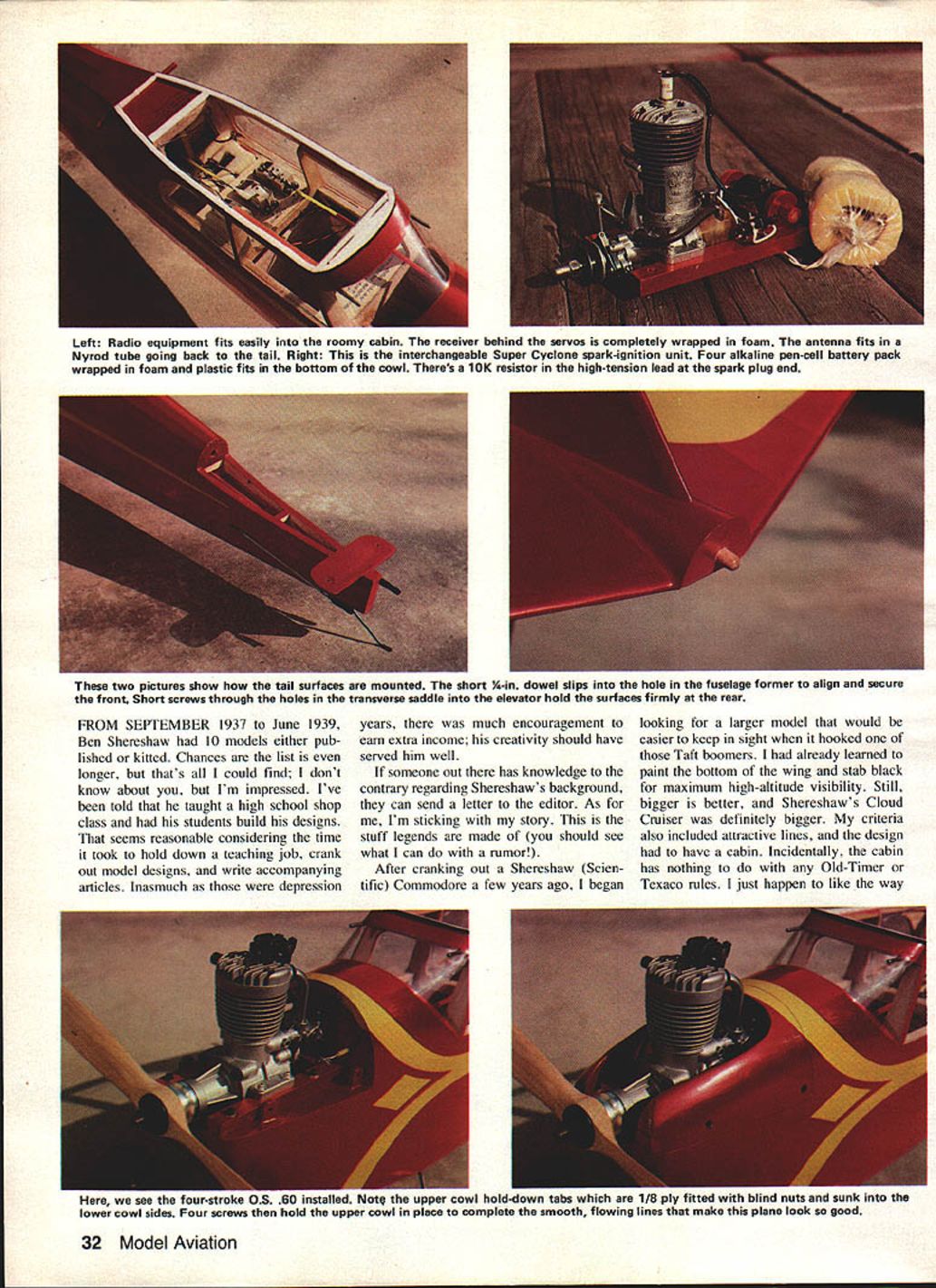
Radio equipment fits easily in the roomy cabin. The receiver (behind servos) is completely wrapped in foam; the antenna fits in a Nylrod tube running back to the tail.
The interchangeable Super Cyclone spark-ignition unit is shown at right in the original article. A four-alkaline pen-cell battery pack, wrapped in foam plastic, fits in the bottom cowl. There's a 10K resistor in the high-tension lead at the spark-plug end. Two pictures show tail surfaces mounted. A short 4-in. dowel slips into a hole in the fuselage former to align and secure the front. Short screws through holes in the transverse saddle hold the elevator surfaces firmly at the rear.
It looks something like Walter Mitty syndrome, though cabins really pose problems. The crash criterion cropped up after the project commenced. An 8-ft. wing won't fit a Toyota Celica; a two-piece wing became necessary. As is usual practice, Old-Timers stick with original shapes and redesign structures — which is what was done on the Cloud Cruiser. I changed the shape of the rear cabin area; the original simply was gross and didn't lend itself to installing a dowel wing hold-down. There was no such provision in the front cabin either, so that was taken care of. (Back in the "good old days," it was fairly common practice to wrap rubber bands completely around the fuselage to hold the wing down. Yuk!)
For those who wish to have a multi-purpose model, be advised that I've provided for removable engine mounts. I use an O.S. .60 four-stroke for Texaco and the Super Cyclone on spark ignition for Antique and Class C competition. Since the Cyclone has to bust a gut to fly this 6½-lb. plane, I'd recommend an Orwick or an Anderson Spitfire for the timed engine run events; I'd use one of these if I had one. With luck you can find a benevolent engine collector who will sell one for less than a house payment. For sport flying, the O.S. is perfect, especially when it comes to keeping peace with the neighbors. That purring four-stroker is a very friendly engine (without a muffler).
Construction
If you've decided to build this beauty, please study the plans before you start. There isn't anything particularly difficult about it beyond its size. I always find myself banging large structures into the light over my work table (the kitchen table) or into walls or whatever else I can find to bang things into. When that happens, and I've finished swearing, I dampen the ding with water, and that usually does the trick. If you accumulate dings after doping, you can forget the water trick; you'll need to get out the talc and dope.
In general, construction is quite conventional. My comments will be limited to specific areas that have some feature that warrants an explanation.
Fuselage
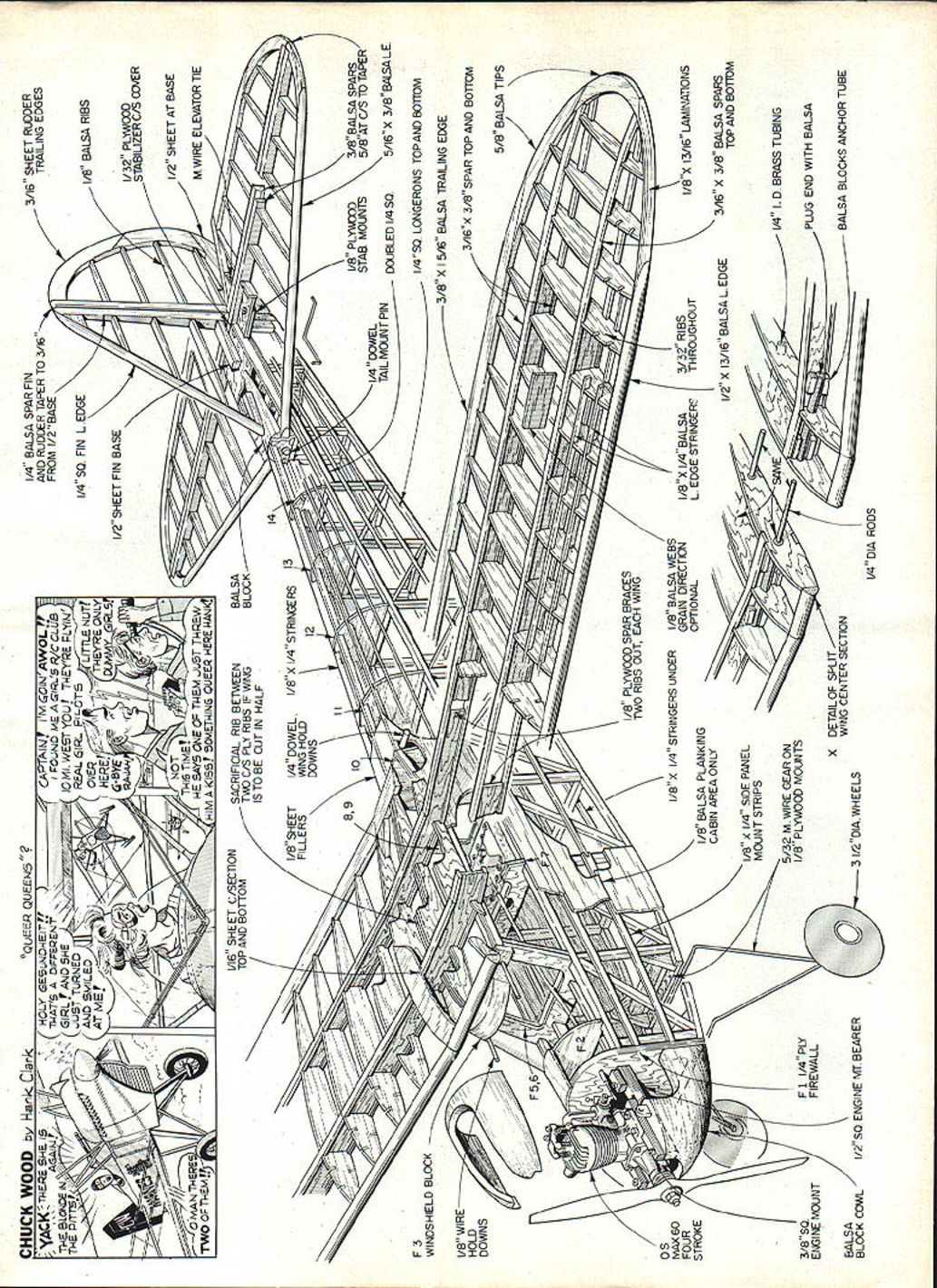
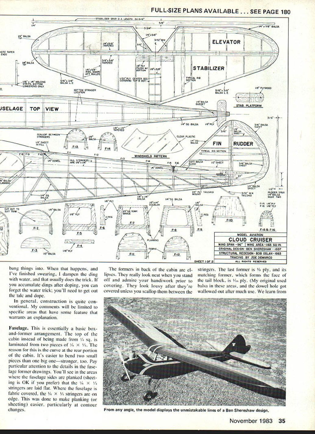
This is essentially a basic box-and-former arrangement. The top of the cabin, instead of being made from 1/4" sq., is laminated from two pieces of 1/8" x 1/4". The reason for this is the curve at the rear portion of the cabin. It's easier to bend two small pieces than one big one — stronger, too. Pay particular attention to the details in the fuselage former drawings. You'll see in the areas where the fuselage sides are planked (sheeting is OK if you prefer) that the 1/8" x 1/4" stringers are laid flat. Where the fuselage is fabric covered, the 1/8" x 1/4" stringers are on edge. This was done to make planking (or sheeting) easier, particularly at contour changes.
The formers in back of the cabin are ellipses. They really look neat when you stand off and admire your handiwork prior to covering. They look lousy after they're covered unless you scallop them between the stringers. The last former is 1/8" ply, and its matching former, which forms the face of the tail block, is also 1/8" ply. (My original used balsa in these areas, and the dowel hole got swallowed out after much use. We learn from our experiences.)
The landing gear and tail skid mount on 1/8" ply in a similar manner. Both are laced to the wood with heavy thread. Tack-glue the wire in place (CyA glue works great), and drill 1/16" holes along both sides of the wire. The holes should be staggered. Lace the wire to the wood with button and carpet thread, starting at one end and then doubling back. Be sure to pull the thread tight. When that's done, soak the thread with CyA, and epoxy the wire/wood area. If you do this properly and the attachment fails in use, then my name isn't Rumplestiltskin.
The cowl serves a structural as well as an aerodynamic purpose. Sure, it cleans up the front of the plane, but it also is part of the engine mount bearer structure. Don't be caught without it. The cowl sides are glued to the bearers. This makes the engine mount extremely rigid and vibration-free. Your airborne radio pack will love you for the smooth ride (don't forget to balance your prop).
Wing
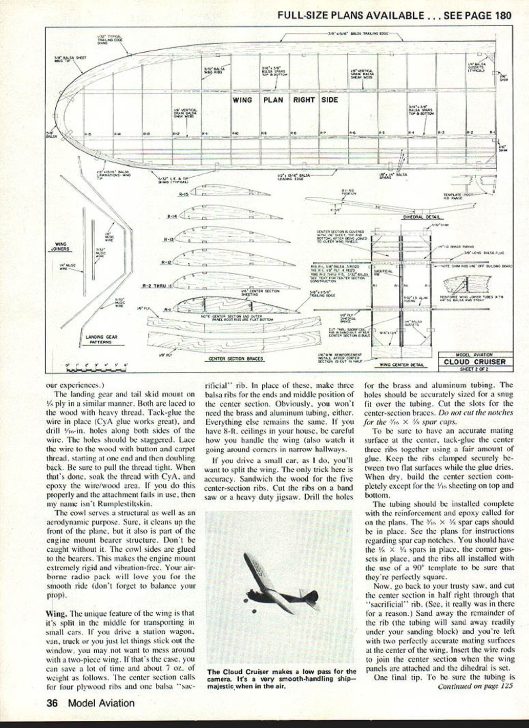
The unique feature of the wing is that it's split in the middle for transporting in small cars. If you drive a station wagon, van, truck or you just let things stick out the window, you may not want to mess around with a two-piece wing. If that's the case, you can save a lot of time and about 7 oz. of weight as follows. The center section calls for four plywood ribs and one balsa sacrificial rib. In place of these, make three balsa ribs for the ends and middle position of the center section. Obviously, you won't need the brass and aluminum tubing, either. Everything else remains the same. If you have 8-ft. ceilings in your house, be careful how you handle the wing (also watch it going around corners in narrow hallways).
If you drive a small car, as I do, you'll want to split the wing. The only trick here is accuracy. Sandwich the wood for the five center-section ribs. Cut the ribs on a band saw or a heavy-duty jigsaw. Drill the holes for the brass and aluminum tubing. The holes should be accurately sized for a snug fit over the tubing. Cut the slots for the center-section braces. Do not cut the notches for the 1/8" x 1/4" spar caps.
To be sure to have an accurate mating surface at the center, tack-glue the center three ribs together using a fair amount of glue. Keep the ribs clamped securely between two flat surfaces while the glue dries. When dry, build the center section completely except for the 1/8" sheeting on top and bottom.
The tubing should be installed complete with the reinforcement and epoxy called for on the plans. The 1/4" x 3/8" spar caps should be in place. See the plans for instructions regarding spar cap notches. You should have the 1/4" x 3/8" spars in place, the center gussets in place, and the ribs all installed with the use of a 90° template to be sure that they're perfectly square.
Now, go back to your trusty saw, and cut the center section in half right through that sacrificial rib. (See, it really was in there for a reason.) Sand away the remainder of the rib (the tubing will sand away readily under your sanding block) and you're left with two perfectly accurate mating surfaces at the center of the wing. Insert the wire rods to join the center section when the wing panels are attached and the dihedral is set.
One final tip. To be sure the tubing is straight when you install it, do it with the wire rods in place. (Don't forget to remove the rods before sawing the center section in half, or a saw blade — and the noise — will weld the fillings in your teeth.)
Tail surfaces
If you've seen one tail section you've seen 'em all. This one isn't any different except that it has a dowel in the front and is held by two screws in the back.
Fuel tank and radio installation
The tank location, size, and style is up to you. I used a 2-oz. metal tank and stuck it behind the firewall above the engine mount bearers. If you want a larger tank, there's plenty of room in the area described. When I fly the ship using the Super Cyclone, I sometimes use the integral Cyclone tank and at other times the internal tank.
The radio gear goes wherever it is needed for proper balance. If you use an O.S. .60 four-stroke, the battery and receiver will have to go as far back as conveniently possible. That engine is quite heavy, but what a jewel it is!
Covering
I suppose most people will opt for one of the quickie heat-shrink covering materials. If so, there's no problem, as the structure is plenty strong. You'll gain more strength by using silk and dope or Silron and dope. I prefer the latter; it's a bit less expensive than silk. More important, it's easier to use and even stronger than silk.
If you use nitrate dope, you'll need a fuel-proof final coat. If you use butyrate dope, you'll need lots of patience. I used butyrate because it's available in colors at the local aircraft supply house, but it can be a bear to use, especially in corners where it refuses to stick. The only thing I can suggest is use thin coats in the corners.
If you can use acetate, nitrate, butyrate or plastic heat-shrink, I suggest you color the bottom of the wing and stab black. That way, even if you're color blind, you can see the airplane at a great distance when it's overhead. Dark opaque colors are also best for distant horizontal visibility.
Flying
That big barn-door rudder really works, so you may find the ship a bit touchy for the first flight or two. Not to worry, lads. Once you get to know her, the old Cloud Cruiser is a real pussycat. The rudder and elevator movements are ±1½ in. and ±1 in., respectively.
As with most Old-Timers, the ship likes to take off dead into the wind. Crosswind take-offs are really thrilling — and are not recommended. If you feel like trying some acrobatics, go to it — but no stick-horsing, please. Big loops and slow rolls are the ticket. If you crank in full-up elevator at the bottom of a 400-ft. dive, don't come crying to me if the wing snaps. This isn't a Pattern ship.
As for thermalling ability, she's as good as the best. And she's big enough to see a long way off — important in Texaco competition. I remember a day at Taft when there was so much lift all around that I couldn't get the ship down without diving. I was sport flying of course; at contests I have located such super downers that it takes power to fly level. Did I ever tell you about that time at the 1975 SAN Champs in Denver? There I was at 5,000 feet trying to climb full bore into a downer....
Transcribed from original scans by AI. Minor OCR errors may remain.

