
Cloudhopper
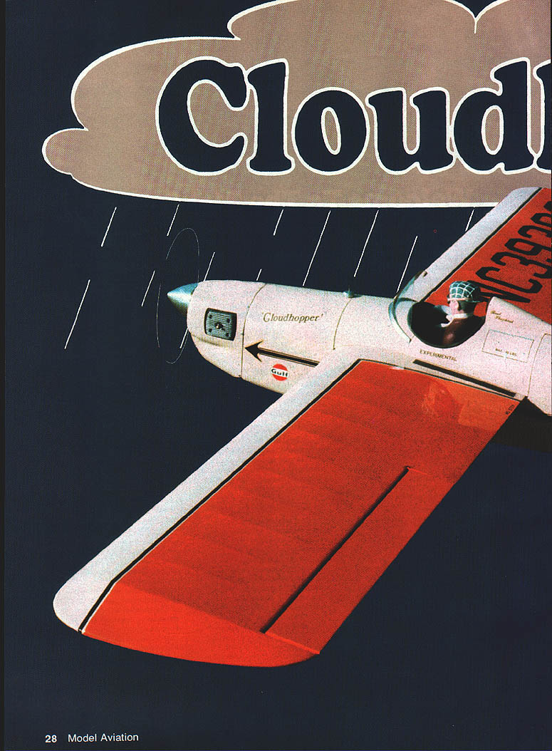
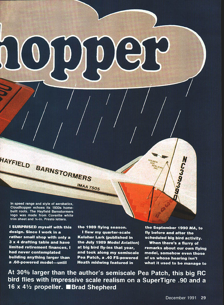
In speed range and style of aerobatics, Cloudhopper echoes its 1930s home-built roots. The Hayfield Barnstormers logo was made from Coverite white trim sheet and 1/4-in. Presto letters.
I surprised myself with this design. Since I work in a rather small shop with only a 3 x 4 drafting table and have limited retirement finances, I had never contemplated building anything larger than a .60-powered model—until the 1989 flying season.
I flew my quarter-scale Keleher Lark (published in the July 1989 Model Aviation) at big-bird fly-ins that year, and took along my semiscale Pea Patch, a .40 FS-powered Heath midwing featured in the September 1990 MA, to fly before and after the scheduled big-bird activity. When there's a flurry of remarks about our own flying model, somehow even those of us whose hearing isn't what it used to be manage to catch every word. Most of the comments about Pea Patch went something like this: "It's a nice airplane and flies great. Now if it were only twice as big ..."
After talking it over with fellow modelers, I decided that a 30% enlargement would meet IMAA requirements and adapt the model for big-bird fly-ins. At 30% larger than the author's semiscale Pea Patch, this big RC bird flies with impressive scale realism on a SuperTigre .90 and a 16 x 4-1/2 propeller.
The larger version, called Cloudhopper, is all I could have hoped for. Equipped with a SuperTigre .90 swinging a Rev-Up 16 x 4-1/2 propeller, this model moves through the air at a scale-like speed reminiscent of the Golden Age home-builts that inspired it.
Once a few weeks of bad weather and turbulence had cleared, I test-flew the airplane on a March afternoon at the Georgetown Modelers' new field in Georgetown, Texas. I bolted on the wing, filled the tank, and fired up the SuperTigre .90. I taxied Cloudhopper down the runway, turned her into the wind, and pushed open the throttle. After about 30 feet the plane rotated off the strip.
I fed in some slight trim changes, then made a few passes and turns. Everything looked good, but I needed more control throw on all surfaces. I gave the model some down trim at full throttle, throttled the engine back for the landing approach, and made a good landing.
Back in Victoria, Texas, in my home workshop, I replaced the elevator and rudder servo arms with longer ones to provide additional throw and moved the aileron link to the upper hole in the ailerons. The modifications proved effective, and on its next flight off the Steen Strip the airplane cut through strong gusts efficiently.
Fitted with the indicated power/prop combination, Cloudhopper does aerobatics appropriate to its heritage and provides good scale realism. Don't expect unlimited aerobatics—you'll get scale-appropriate maneuvers, not the 3-D performance of an Extra 230.
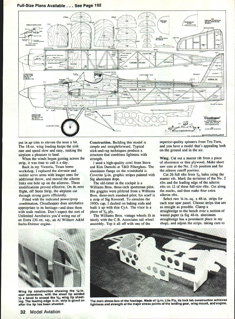
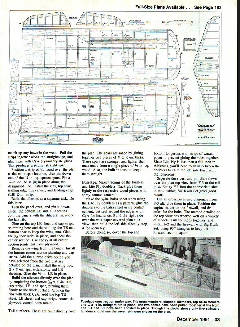
Full-size plans available (page 192).
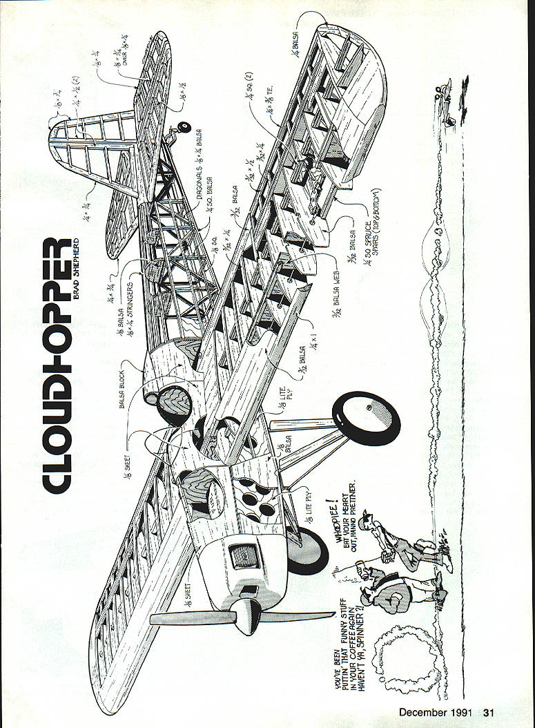
Construction
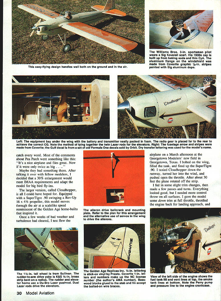
Building the model is simple and straightforward. Typical stick-and-rag techniques produce a structure that combines lightness and strength. I used a high-quality cowl from Steve and Kim Durecki at T&D Fiberglass. The aluminum flange on the windshield was made from thin aluminum. The trim stripes were cut from Coverite graphic sheet and painted with Sig aluminum dope.
The old-timer cockpit features a Williams Bros. three-inch sportsman pilot. The 1930s cap was built up from baking soda and thin CyA, and the visor was formed from 3/32 ply. Vintage-style wheels fit nicely and a Sullivan 1-1/4-in. tailwheel assembly was used. Top it off with a superior-quality Tru-Turn spinner and you have an airplane that's appealing both on the ground and in the air.
Wing
- Cut out a master rib from thin plywood or aluminum and make short saw cuts for the rib profile, noting the No. 2 rib position and the aileron cutoff location.
- Cut 26 full ribs from 3/32 balsa using the master rib as a template. For the ailerons, mark and cut 12 full-size ribs; cut along the marks to make the necessary aileron and wing parts. Make four extra aileron ribs.
- Select two 1/4-in.-sq. x 48-in. strips for each rear spar panel. Choose strips that are as straight as possible. Clamp a straightedge to the bench over a section of waxed paper and adjoin the strips, matching any bows. Pull the strips together along the straightedge and glue them with CyA to produce a strong, straight spar.
- Position a strip of 3/16-in. wood over the plan at the main spar location, then pin down one of the 1/4-in.-sq. spar caps. Pin a 1/4-in.-sq. balsa jig along the designated line. Install the ribs, top spar, trailing edge (TE) sheet, and leading edge (LE) 1/2-in. strip.
- Build the ailerons as a separate task: construct directly over the plan by placing the bottom 3/32 x 1/2-in. TE, cap strips, LE, and spar; pin firmly, glue ribs with thick CyA, add top TE sheet, LE sheet, cap strips, and attach the plywood control-horn mount.
- Turn the panel over and install bottom LE and TE sheeting. Join panels with the dihedral jig under the last rib.
- Glue on top LE sheet and cap strips, shimming along the TE and bottom spar to keep the wing true. Glue the 3/32-in. spar webs in place and sheet the center section, using epoxy at all center-section joints that have plywood.
- Install the bottom center-section sheeting and cap strips. Add the aileron drive option selected from the plan. Install wing tips, 5/8 x 1/4-in. spar extensions, and LE sheeting. Glue the 1/4-in. LE in place.
The 18-oz. wing loading keeps the sink rate and speed slow and easy, making the airplane a pleasure to land.
Tail surfaces
- Build tail surfaces directly over the plan.
- Make the spars by gluing together two pieces of 1/4 x 1/2-in. balsa; this produces spars stronger and lighter than a single 1/2-in.-sq. piece and retains a straight tension.
Fuselage
- Make tracings of the formers and Lite Ply doublers. Tack glue them lightly to the respective wood pieces with spray contact cement.
- Make the 1/8-in. balsa sheet sides using the Lite Ply doublers as a pattern; glue doublers to the balsa with contact cement and seal edges with CyA for insurance.
- Build the right side over the wax-paper-covered plan side view, then build the left side directly atop it for accuracy. Cover top and bottom longerons with strips of waxed paper to prevent gluing the sides together. Since Lite Ply is less than a full inch thick, shim between the doublers to raise the left side flush with the longerons.
- Separate the sides, pin them down over the plan from F-3 to the tail post, and epoxy F-3 into the appropriate slots in the doubler (Sig Kwik Set works well).
- Cut all crosspieces and diagonals from 3/8-in. plywood and glue them in place. Position the engine mount on the firewall, drill holes for the bolts, pull the sides together, and install F-2 and the firewall with Sig Kwik Set, using 90° triangles to keep the forward section square.
- Glue the bottom crosspieces to the frame and attach the 1/4-in. sheeting between F-2 and the rear landing gear-mount block location.
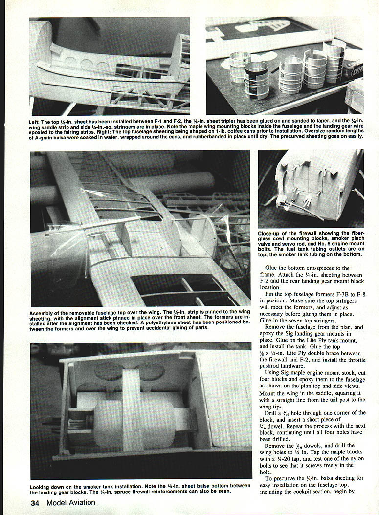
- Pin top fuselage formers F-3B to F-8 in position. Make sure the top stringers will meet the formers and adjust before gluing. Glue in the seven top stringers.
- Remove the fuselage from the plan and epoxy the Sig landing-gear mounts in place. Glue on the Lite Ply tank mount and install the tank. Glue the top 1/8 x 1/2-in. Lite Ply double brace between the firewall and F-2, and install the throttle pushrod hardware.
- Using Sig maple engine-mount stock, cut four blocks and epoxy them to the fuselage as shown on the plan top and side views. Mount the wing in the saddle, squaring it with a straight line from the tail post to the wing tips.
- Drill a 3/16-in. hole through one corner of each block and insert short 3/16-in. dowels. Remove the dowels and drill the wing holes to 1/4 in. Tap the maple blocks with a 4-20 tap and test one of the nylon bolts to ensure it screws freely.
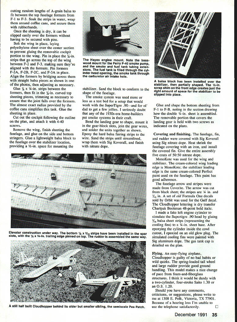
- To precure the 1/8-in. balsa sheeting for the fuselage top, cut random lengths of A-grain balsa to fit between the top formers from F-1 to F-3. Soak the strips in water, wrap them around coffee cans, and secure with rubber bands. Once dry, the sheeting slips easily over the formers without many pins.
- Bolt the wing in place and lay polyethylene sheet over the center section to prevent gluing the removable cockpit portion to the wing. Pin 1/4-in. strips across the top of the wing between F-2 and F-3, making sure they align with the formers. Pin formers F-2A, F-2B, F-2C, and F-3A in place and align by bridging across them with straight balsa pieces, adjusting as necessary.
- Glue 1/8 x 1/4-in. strips between the formers, then fit the 1/8-in. curved top sheeting pieces trimmed so the joint falls over formers. Glue sheeting in place.
- Cut out the cockpit following the plan outline and attach it with 4-40 screws. Remove the wing, finish sheeting the fuselage, and glue on the side and bottom stringers.
- Glue a lightweight balsa block to the fuselage over the stabilizer location, providing a 1/2-in. space for mounting the stabilizer. Sand the block to conform to the fuselage shape.
- Bend the landing gear to shape, mount it in the gear-block slots, join the gear wires and solder the units together as shown. Epoxy the hard balsa fairing strips to the wire, sand them streamlined, wrap with Sig Koverall, and finish with nitrate dope.
- Glue and shape the bottom sheeting from F-1 to F-8, noting how the double 1/4-in. sheet is assembled. The removable portion that covers the landing gear is held with two screws as indicated on the plans.
The smoke system was used more or less as a test bed for a setup that would work with the SuperTigre .90—and for old dad to get a few jollies. I seriously doubt that any of the 1930s-era home-builders put smoke systems in their craft.
Covering and finishing
- The fuselage, fin, and rudder were covered with Sig Koverall using Sig nitrate dope. Heat-shrink the fuselage covering with an iron, install the covered fin, and give the entire assembly two coats of 50:50 nitrate dope.
- MonoKote was used for the wing and stabilizer. The cream-colored wing leading edge is MonoKote; the stabilizer leading edge is the same cream-colored Perfect paint used on the fuselage (this paint has good adhesion).
- The fuselage arrow and stripes were made from Coverite. The arrow was cut from black sheet; the stripes are 1/4 in. and 1/8 in. A set of old Formula One decals sold by Orbit was used for the Gulf decal. The Cloudhopper lettering is dry-transfer Chartpak Bookman 48-point bold italic.
- I made a fake left engine cylinder to simulate the SuperTigre .90 head by gluing 1/16-in. balsa sheet strips (representing the cooling fins) to a 1/4-in. sheet base. After epoxying the cylinder inside the cowl cutout, I epoxied on an old glow plug. The simulated cooling fins were painted with Sig aluminum dope. The gas-tank cap is detailed on the plan.
Flying
Cloudhopper is an easy-flying airplane with no bad habits or wild quirks. The spring-loaded tailwheel and large rudder provide good ground handling. It makes a nice change of pace from foam-and-fiberglass structures. I think it would be dandy with a two-cylinder, four-stroke Saito 1.30 or an O.S. 1.20.
An 18-oz. wing loading keeps sink rate and speed slow, making the airplane a pleasure to land. When winds begin gusting across the strip, Cloudhopper still handles well—after the control-throw modifications mentioned earlier it cut through strong gusts efficiently.
Should you have any comments, criticisms, or suggestions, please write to me at:
1308 E. Polk Victoria, TX 77901
Because of a hearing loss I'm unable to use the telephone satisfactorily.
Transcribed from original scans by AI. Minor OCR errors may remain.

