
CO-2 Cub
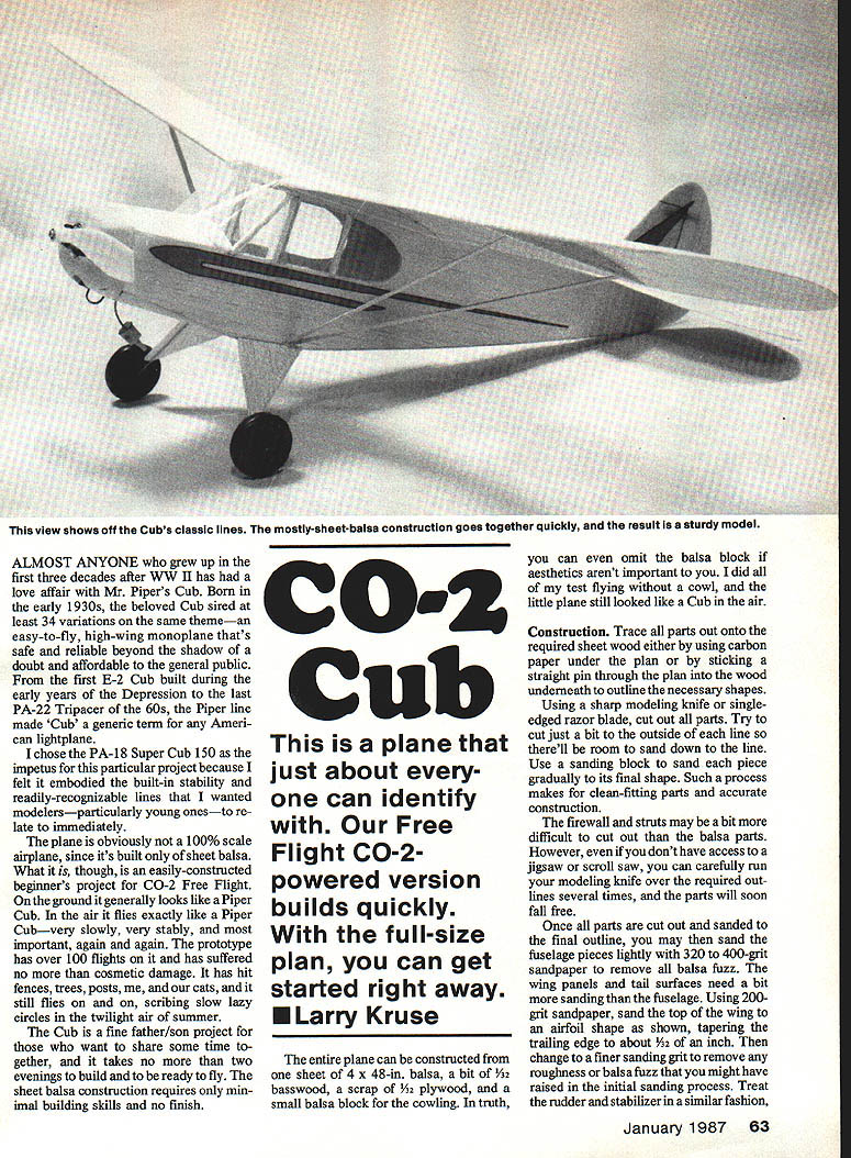
Almost anyone who grew up in the first three decades after WW II has had a love affair with Mr. Piper's Cub. Born in the early 1930s, the beloved Cub sired at least 34 variations on the same theme—an easy-to-fly, high-wing monoplane that's safe and reliable beyond the shadow of a doubt and affordable to the general public.
From the first E-2 Cub built during the early years of the Depression to the last PA-22 Tri-Pacer of the '60s, the Piper line made "Cub" a generic term for any American lightplane.
I chose the PA-18 Super Cub 150 as the impetus for this particular project because I felt it embodied the built-in stability and readily recognizable lines that I wanted modelers—particularly young ones—to relate to immediately.
The plane is not a 100% scale airplane, since it's built only of sheet balsa. What it is, though, is an easily constructed beginner's project for CO-2 free flight. On the ground it generally looks like a Piper Cub. In the air it flies exactly like a Piper Cub—very slowly, very stably, and, most important, again and again. The prototype has over 100 flights on it and has suffered no more than cosmetic damage. It has hit fences, trees, posts, me, and our cats, and it still flies on and on, scribing slow, lazy circles in the twilight air of summer.
The Cub is a fine father/son project for those who want to share some time together, and it takes no more than two evenings to build and be ready to fly. The sheet balsa construction requires only minimal building skills and no finish.
You can even omit the balsa cowl block if aesthetics aren't important. I did all of my test flying without a cowl, and the little plane still looked like a Cub in the air.
This is a plane that just about everyone can identify with. Our free flight CO-2–powered version builds quickly. With the full-size plan, you can get started right away.
—Larry Kruse
Construction
Trace all parts onto the required sheet wood either by using carbon paper under the plan or by sticking a straight pin through the plan into the wood underneath to outline the necessary shapes. Using a sharp modeling knife or single-edged razor blade, cut out all parts. Try to cut just a bit to the outside of each line so there will be room to sand down to the line. Use a sanding block to sand each piece gradually to its final shape. This process makes for clean-fitting parts and accurate construction.
The firewall and struts may be a bit more difficult to cut out than the balsa parts. However, even without a jigsaw or scroll saw you can carefully run your modeling knife over the required outlines several times, and the parts will soon fall free.
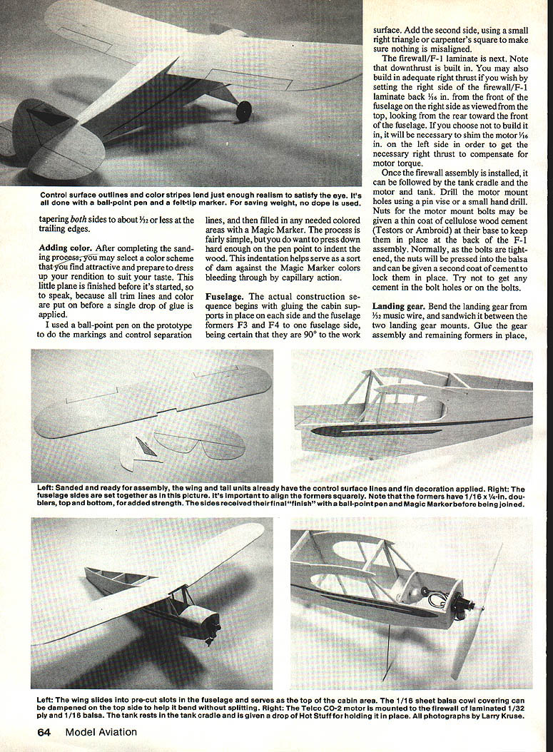
Once all parts are cut out and sanded to the final outline, sand the fuselage pieces lightly with 320- to 400-grit sandpaper to remove all balsa fuzz. The wing panels and tail surfaces need a bit more sanding than the fuselage. Using 200-grit sandpaper, sand the top of the wing to an airfoil shape as shown on the plan, tapering the trailing edge to about 1/32 in. Then change to a finer sanding grit to remove any roughness or balsa fuzz you might have raised in the initial sanding process. Treat the rudder and stabilizer in a similar fashion, tapering both sides to about 3/32 in. or less at the trailing edges.
Adding color
After completing the sanding process, select a color scheme and prepare to dress up your rendition to suit your taste. This little plane is finished before it's started, so to speak, because all trim lines and color are put on before a single drop of glue is applied.
On the prototype I used a ball-point pen for the markings and control separation lines, then filled in colored areas with a Magic Marker. The process is simple, but press down hard enough with the pen to indent the wood. This indentation helps serve as a dam against Magic Marker colors bleeding by capillary action.
Fuselage
The actual construction sequence begins with gluing the cabin supports in place on each side and the fuselage formers F3 and F4 to one fuselage side, making certain they are 90° to the work surface. Add the second side, using a small right triangle or carpenter's square to make sure nothing is misaligned.
Next install the firewall/F-1 laminate. Note that downthrust is built in. You may also build in adequate right thrust by setting the right side of the firewall/F-1 laminate back 1/16 in. from the front of the fuselage on the right side as viewed from the top (looking from the rear toward the front). If you choose not to build right thrust into the firewall, it will be necessary to shim the motor 1/16 in. on the left side to compensate for motor torque.
Once the firewall assembly is installed, add the tank cradle and the motor and tank. Drill motor mount holes using a pin vise or a small hand drill. Nuts for the motor mount bolts may be given a thin coat of cellulose wood cement (Testors or Ambroid) at their base to keep them in place at the back of the F-1 assembly. Normally, as the bolts are tightened the nuts will be pressed into the balsa and can be given a second coat of cement to lock them in place. Try not to get any cement in the bolt holes or on the bolts.
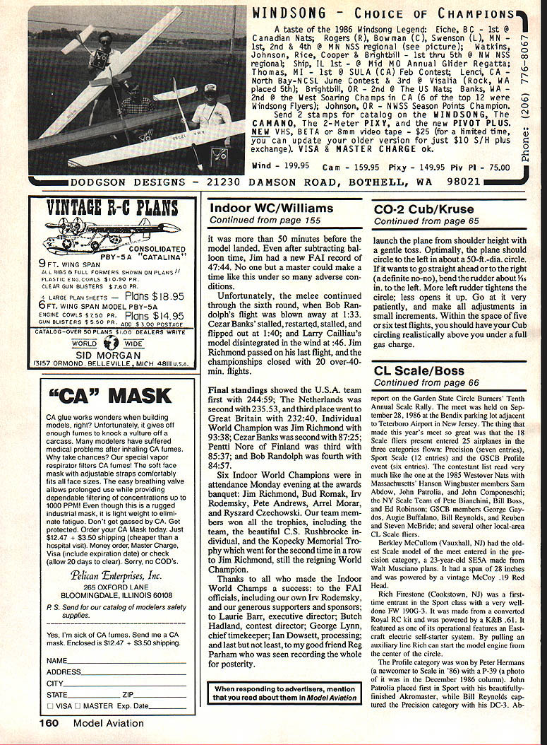
Cut out a half-circle area just in back of the firewall to allow the CO-2 filler tube and nozzle to protrude far enough to make filling easy. After the bottom sheeting is in place, set the fuselage aside until final assembly.
Landing gear
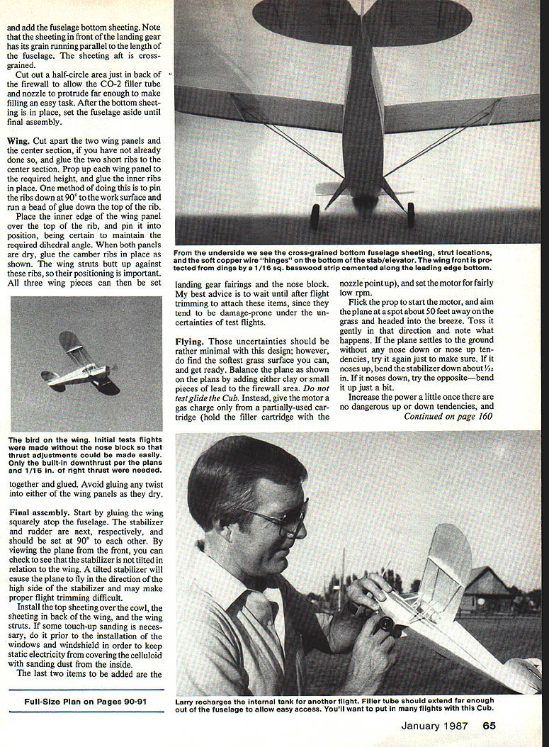
Bend the landing gear from 3/32 in. music wire, and sandwich it between the two landing gear mounts. Glue the gear assembly and remaining formers in place, and add the fuselage bottom sheeting. Note that the sheeting in front of the landing gear has its grain running parallel to the length of the fuselage; the sheeting aft is cross-grained.
Wing
Cut apart the two wing panels and the center section, if you have not already done so, and glue the two short ribs to the center section. Prop up each wing panel to the required height, and glue the inner ribs in place. One method is to pin the ribs down at 90° to the work surface and run a bead of glue down the top of each rib.
Place the inner edge of the wing panel over the top of the rib, and pin it into position, being certain to maintain the required dihedral angle. When both panels are dry, glue the camber ribs in place as shown on the plan. On the bottom, strip-balsa up against these ribs, so their positioning is important. All three wing pieces can then be set together and glued. Avoid gluing any twist into either wing panel as they dry.
Final assembly
Start by gluing the wing squarely atop the fuselage. The stabilizer and rudder are next, respectively, and should be set at 90° to each other. By viewing the plane from the front, check that the stabilizer is not tilted in relation to the wing. A tilted stabilizer will cause the plane to fly to the high side and may make proper flight trimming difficult.
Install the top sheeting over the cowl, the sheeting in back of the wing, and the wing struts. If some touch-up sanding is necessary, do it prior to installing the windows and windshield in order to keep static electricity from covering the celluloid with sanding dust from the inside.
The last two items to be added are the landing gear fairings and the nose block. Wait until after flight trimming to attach these items, since they tend to be damage-prone during test flights.
Flying
Find the softest grass surface you can and get ready. Balance the plane as shown on the plans by adding clay or small pieces of lead to the firewall area. Do not test-glide the Cub. Instead, give the motor a gas charge only from a partially used cartridge (hold the filler cartridge with the nozzle point up), and set the motor for fairly low rpm.
Flick the prop to start the motor, and aim the plane at a spot about 50 ft away on the grass and headed into the breeze. Toss it gently in that direction and note what happens. If the plane settles to the ground without nose-down or nose-up tendencies, try it again to be sure. If it noses up, bend the stabilizer down about 1/32 in. If it noses down, bend the stabilizer up just a bit.
Increase the power a little once there are no dangerous up or down tendencies, and enjoy flying your CO-2 Cub. Launch the plane from shoulder height with a gentle toss. Optimally, the plane should circle to the left in about a 50 ft. diameter circle. If it wants to go straight ahead or to the right (a definite no-no), bend the rudder about 1/16 in. to the left. More left rudder tightens the circle; less opens it up.
Make all adjustments in small increments and be patient. Within five or six test flights, you should have your Cub circling realistically above you under a full gas charge.
Transcribed from original scans by AI. Minor OCR errors may remain.

