
CO2 Replica: deBolt's 1946 Airfoiler
A.A. Lidberg
Resurrected from 1946, this down-sized version shows off the engineering talents of a young designer who has become a fixture on the modeling scene.
If you've been following the CO2 replicas I've done for Model Aviation in the past, then you know we've taken a look at some really interesting models, both from the Old Timer and later Nostalgia periods. My selection this time falls just at the start of the Nostalgia period, as it was originally kitted in 1946. In the back of my mind I remembered the Airfoiler from magazine ads of the mid-1940s, and I was fortunate to locate an original set of plans.
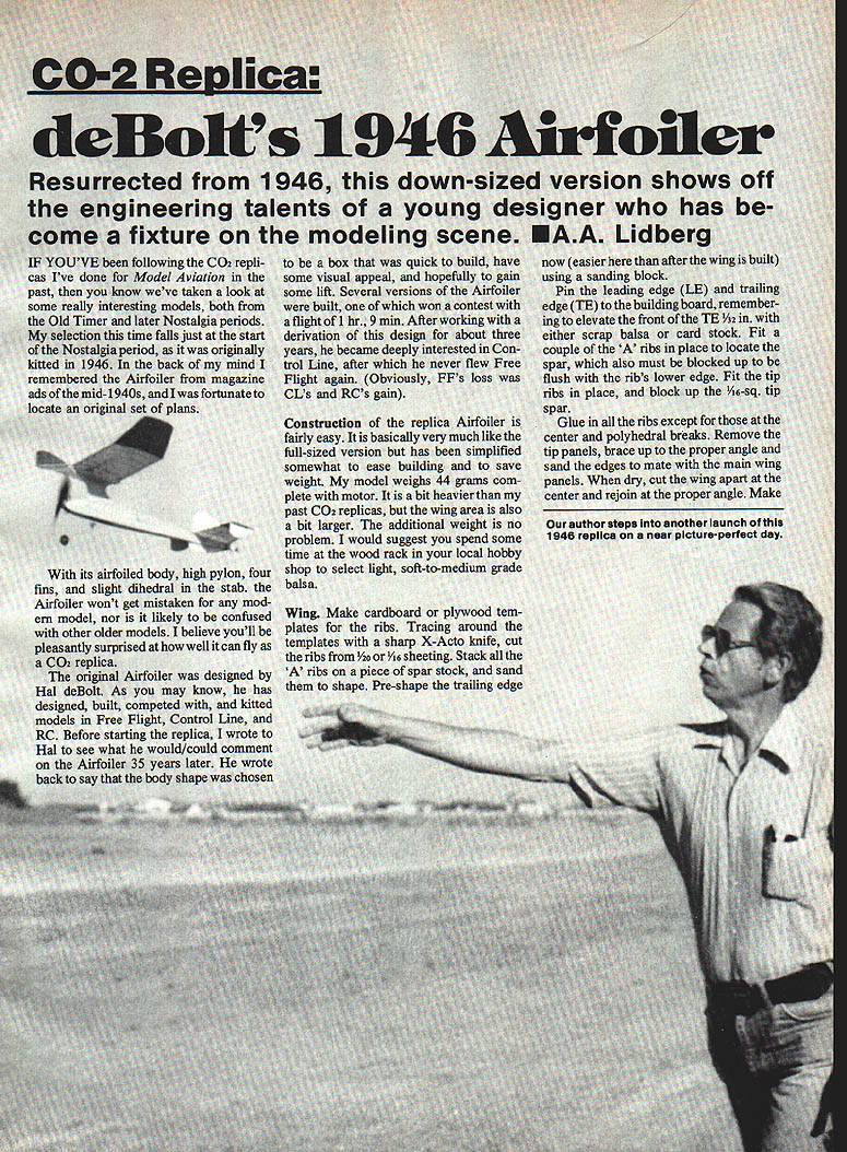
With its airfoiled body, high pylon, four fins, and slight dihedral in the stab, the Airfoiler won't be mistaken for any modern model, nor is it likely to be confused with other older models. I believe you'll be pleasantly surprised at how well it can fly as a CO2 replica.
Designer notes
The original Airfoiler was designed by Hal deBolt. He has designed, built, competed with, and kitted models in Free Flight (FF), Control Line (CL), and RC. Before starting the replica, I wrote to Hal to see what he would/could comment on the Airfoiler 35 years later. He wrote back to say that the body shape was chosen to be a box that was quick to build, have some visual appeal, and hopefully to gain some lift. Several versions of the Airfoiler were built, one of which won a contest with a flight of 1 hr., 9 min. After working with a derivation of this design for about three years, he became deeply interested in Control Line, after which he never flew Free Flight again.
Construction of the replica Airfoiler is fairly easy. It is basically very much like the full-sized version but has been simplified somewhat to ease building and to save weight. My model weighs 44 grams complete with motor. It is a bit heavier than my past CO2 replicas, but the wing area is also a bit larger. The additional weight is no problem. I suggest you spend some time at the wood rack in your local hobby shop to select light, soft-to-medium grade balsa.
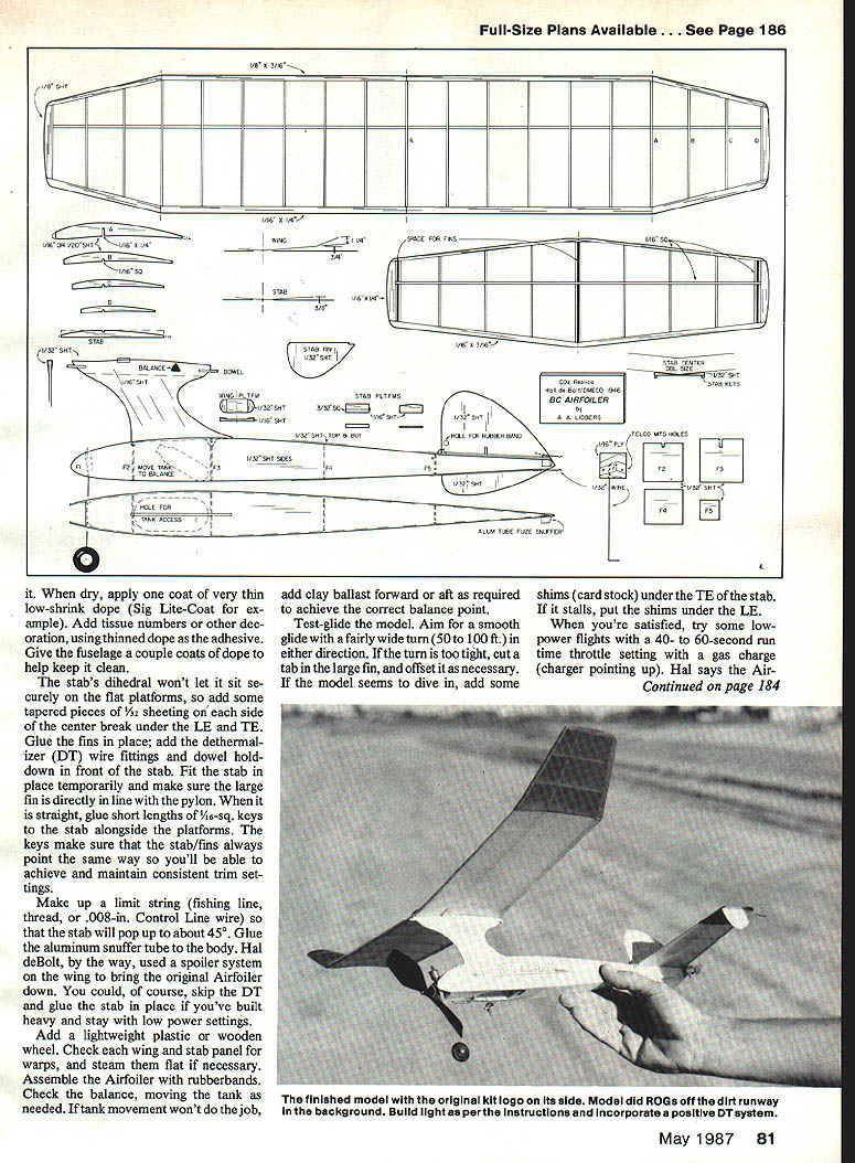
Full-size plans available. See page 186.
Construction
#### Wing
- Make cardboard or plywood templates for the ribs.
- Trace around the templates with a sharp X-Acto knife and cut the ribs from 1/16" or 3/32" sheeting.
- Stack all the ribs on a piece of spar stock and sand them to shape.
- Pre-shape the trailing edge (TE) now — it's easier here than after the wing is built — using a sanding block.
- Pin the leading edge (LE) and TE to the building board, elevating the front of the TE 1/32" with scrap balsa or card stock.
- Fit a couple of the 'A' ribs in place to locate the spar; block up the spar so it is flush with the ribs' lower edge.
- Fit the tip ribs and block up the 1/16"-sq. tip spar.
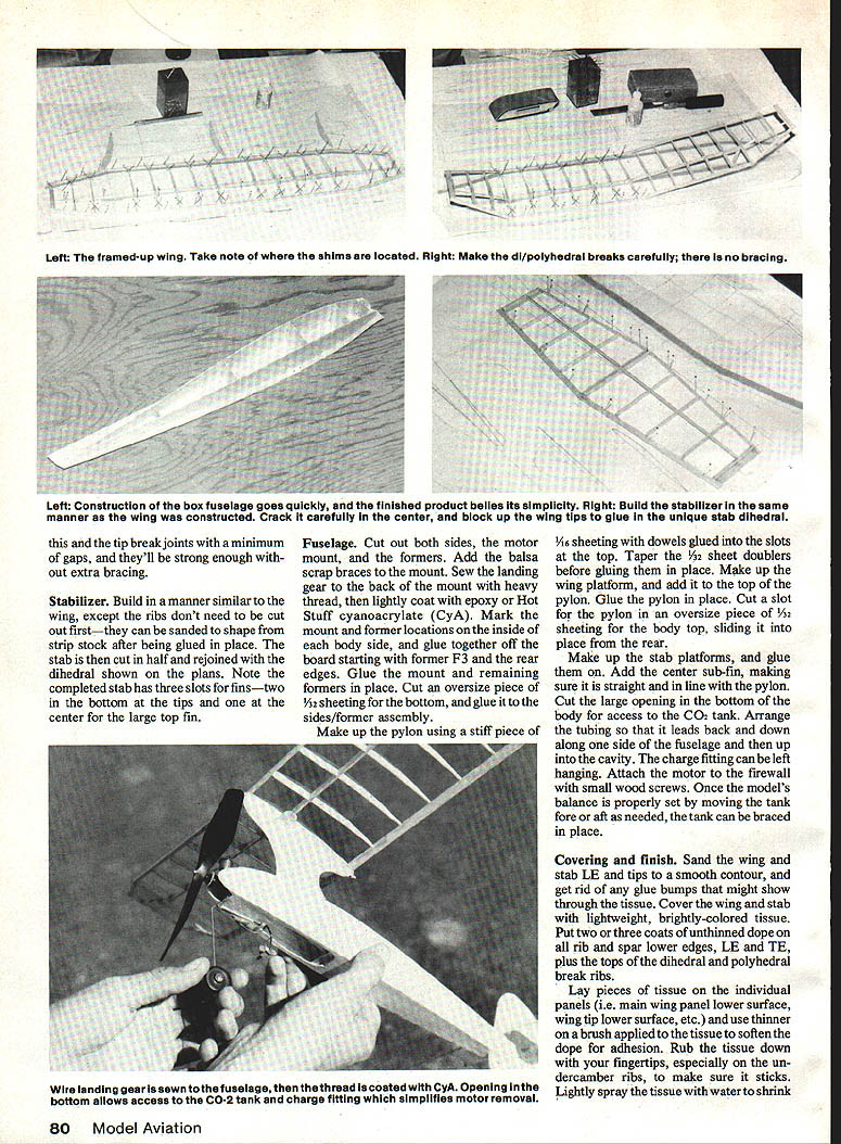
- Glue in all the ribs except those at the center and polyhedral breaks.
- Remove the inner tip panels, brace up to the proper angle and sand the edges to mate with the main wing panels.
- When dry, cut the wing apart at the center and rejoin at the proper angle.
#### Stabilizer
- Build the stabilizer in much the same manner as the wing, except the ribs do not need to be cut out first — they can be sanded to shape from strip stock after being glued in place.
- Cut the stab in half at the center block, prop up the tips, and glue the unique dihedral tip-break joints with a minimum of gaps; they will be strong enough without extra bracing.
- Rejoin the stab halves with the dihedral shown on the plans.
- Note the completed stab has three slots for fins — two lower tip fins and a large center top fin.
#### Fuselage
- Cut out both sides and the motor-mount formers. Add balsa scrap braces and mount the landing gear.
- Sew the landing gear to the back-mount with heavy thread, then lightly coat the thread with epoxy or Hot Stuff cyanoacrylate (CyA).
- Mark mount-former locations inside one body side.
- Glue the two sides together off the board starting at former F3 (rear edges).
- Glue and mount the remaining formers in place.
- Cut an oversize piece of 1/32" sheeting for the bottom and glue it to the sides/former assembly.
- Make up the pylon using a stiff piece of 1/16" sheeting with dowels glued into slots at the top. Taper 1/32" sheet doublers before gluing them in place.
- Make up the wing platform and add it to the top of the pylon. Glue the pylon in place.
- Cut a slot for the pylon in an oversize piece of 1/32" sheeting for the body top and slide it into place from the rear.
- Make up the stab platforms and glue them on. Add a center sub-fin, making sure it is straight and in line with the pylon.
- Cut a large opening in the bottom of the body for access to the CO2 tank. Arrange the tubing so it leads back and down along one side of the fuselage and then up into the cavity so the charge fitting can be left hanging.
- Attach the motor firewall with small wood screws. Once the model is balanced properly, set the tank fore or aft as needed and brace it in place.
Covering and finish
- Sand the wing and stab leading edges and tips to a smooth contour and remove any glue bumps that might show through the tissue.
- Cover the wing and stab with lightweight, brightly colored tissue.
- Put two or three coats of unthinned dope on rib and spar lower edges, LE, TE, and the tops of the dihedral/polyhedral break ribs.
- Lay pieces of tissue as individual panels (for example, main wing panel lower surface, wing tip lower surface, etc.).
- Use a thinner on a brush to soften the dope for adhesion, then rub the tissue down with your fingertips, especially on undercamber ribs.
- Lightly spray the tissue with water to shrink.
- When dry, apply a coat of very thin, low-shrink dope (Sig Lite-Coat, for example).
- Add tissue numbers and other decoration using thinned dope as adhesive.
- Give the fuselage a couple coats of dope to help keep it clean.
Additional finishing notes:
- The stabs' dihedral won't let them sit securely flat on the platforms; add tapered pieces of 1/32" sheeting to the side of the center break under the LE and TE.
- Glue the fins in place.
- Add dethermalizer (DT) wire fittings and a dowel hold-down at the front of the stab.
- Fit the stab temporarily and make sure the large fin is directly in line with the pylon. When straight, glue short lengths of 1/4"-sq keys alongside the platforms to key the stab. Make sure the stab and fins always point the same way to maintain consistent trim settings.
- Make up a limit string (fishing line) threaded through 0.008" control-line wire. The stab will pop up about 45°.
- Glue an aluminum snuffer tube to the body if desired. Hal deBolt's installation used a spoiler system on the wing to bring the original Airfoiler down; you can omit the DT if you prefer.
- If the DT is heavy, stay at low power settings. Add a lightweight plastic or wooden wheel.
Assembly, trim and checks
- Check each wing and stab panel for warps; steam them flat if necessary.
- Assemble the Airfoiler with rubber bands.
- Check the balance, moving the tank as needed. If tank movement won't achieve the correct balance point, add clay ballast forward or aft as required.
- Test-glide the model aiming for a smooth glide with a fairly wide turn (50 to 100 ft.) in either direction.
- If the turn is too tight, cut a tab in the large fin and offset it as necessary.
- If the model seems to dive, add shims (cardstock) under the TE of the stab.
- If it stalls, add shims under the LE.
Flying tips and power settings
- Start with low-power flights using a 40- to 60-second run-time throttle setting with a gas charge (charger pointing up).
- Hal says the Airfoiler should climb to the left (usually considered the kiss of death for a pylon model), and my replica Airfoiler climbs nicely in a wide left turn.
- If your model exhibits tight turning tendencies under power, put shims between the motor and the mount to deflect the thrust line for the opposite turn.
- As you firm up trim settings, switch to a light charge (charger pointing down) and experiment with the throttle settings.
- Most of my CO2 replicas fly longer when the motor is operated at somewhat less than full power.
Test flights and experience
I was very pleased with the way the replica Airfoiler flew the first day out. I am cautious and use a DT fuse even for low-power test flights. With this model it was a wise precaution: the first three flights detonated at about 200 ft. and then rose after about a 90-second flight. There was a substantial thermal column at the field that day which seemed to stay in one place for an hour or more. After a few more flights like that, we tried ROGs from the dirt. The Airfoiler lifted off nicely, although with CO2-powered models, ROGs always seem to cost a lot of altitude.
Hope you've enjoyed this little trip into modeling's history. These replicas enable us to make examples of many neat models with little fitting up of the workshop or going broke in the process. Enjoy — fly CO2.
Transcribed from original scans by AI. Minor OCR errors may remain.

