
CO-2 Swatt
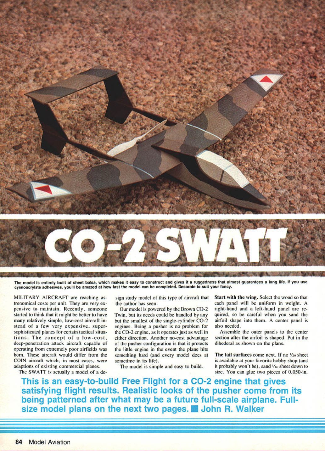
The CO-2 Swatt is an easy-to-build, rugged free-flight model constructed entirely of sheet balsa. It was developed as a small-scale design study of a low-cost, deep-penetration attack aircraft concept — an alternative to very expensive, highly sophisticated military types. The model is well suited to CO-2 power (the author used a Brown Twin CO-2), but most single-cylinder CO-2 engines (except the very smallest) will suffice.
Concept / Background
- Rising costs and maintenance of full-scale military aircraft have led to interest in relatively simple, low-cost aircraft for certain tactical roles.
- The Swatt represents a study of such an aircraft: simple, inexpensive, capable of operating from poor fields, and hardy in operation.
- The pusher configuration protects the engine in impacts and gives the model a distinctive appearance. CO-2 engines operate well in either rotation direction.
Materials and Tools
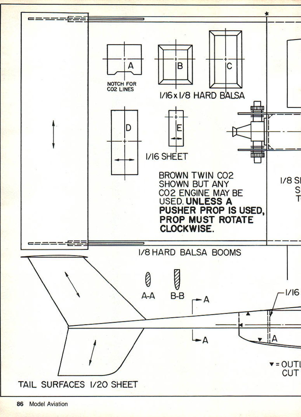
- Sheet balsa (various thicknesses): center wing panel, outer panels, 1/16" and 1/20" for tail surfaces (or sand 1/16" down to 1/20"), 0.050" sheet (two pieces glued together is an alternative).
- 1/8" hard balsa for tail booms.
- Piano wire (.030–.040") for optional skid "whiskers."
- CO-2 engine (Brown Twin shown, any suitable CO-2 may be used).
- Cyanoacrylate adhesives (CyA) — examples: Hot Stuff, Jet, Zap.
- Sanding block, abrasive paper, flat piece of wood for sanding.
- Glue/cement for balsa assembly.
- Tank and fittings for CO-2 engine.
- Dope with plasticizer or MonoKote for finishing.
- Clay for trim testing.
Construction
Wing
- Select wood so each wing panel is uniform in weight.
- Prepare a right-hand and a left-hand outer panel and a center panel.
- Sand the airfoil into the outer panels carefully; be consistent between left and right.
- Assemble the outer panels to the center section after shaping the airfoil.
- Set the dihedral as shown on the plans.
Tail Surfaces
- If 1/20" sheet is unavailable, sand 1/16" sheet down or glue two pieces of 0.050" sheet to achieve the required thickness.
- Sand stabilizer and vertical fins to an approximate airfoil shape; avoid making the leading and trailing edges feather-thin.
Tip: Use a simple sanding jig if available (piano-wire supports or similar) and abrasive paper on a flat block to achieve even thickness and contour.
Tail Booms and Assembly
- Cut tail booms to shape and sand to the proper cross section.
- Assemble the wing, tail surfaces, and booms into a single unit once shaped.
Fuselage
- Cut and/or fabricate fuselage formers.
- Draw the fuselage outline and recommended former locations on the fuselage sides before cutting; prepare distinct right-hand and left-hand sides.
- Assemble the sides and formers; ensure all joints are well cemented or glued.
Engine and Tank Installation
- Install the tank and CO-2 engine in the fuselage.
- With the engine mounted, perform a bench test run to confirm functionality and to make any necessary adjustments — it’s easier now than after final assembly.
- Protect the engine from dust during remaining construction.
Final Assembly
- Slide the wing-tail unit into place and glue securely.
- Add top fuselage sheeting.
- Give the whole model a final sanding; remove glue bumps and rough areas with fine-grit sandpaper.
Finishing and Decoration
- Paint camouflage if desired: irregular strips of dark brown and light brown dope on upper surfaces, light gray below.
- Use dope with a plasticizer added to prevent destructive warping.
- Canopy area may be doped white or covered with white or silver MonoKote trim.
- Be sure to place your name, address, and phone number in a conspicuous place on the model.
Flying
- Before powered flight, test-glide the model over grass.
- Add clay fore or aft until you obtain a nice, smooth glide.
- For the first powered flight use a partial CO-2 charge.
- If using a regular prop, it must be reversed on the shaft so the shaft operates in a clockwise direction.
- Launch with a smooth shove and observe the flight pattern.
- If flight is erratic, check for warps and remove them by steaming.
- Adjust engine thrust line with shims of cardboard or wood if needed.
- After trimming and satisfactory partial-charge flights, proceed to flights on a full CO-2 charge.
- Flight behavior: model typically climbs out, may maintain altitude and circle for a time depending on temperature and cartridge charge, then begin a slow power descent.
Tips and Notes
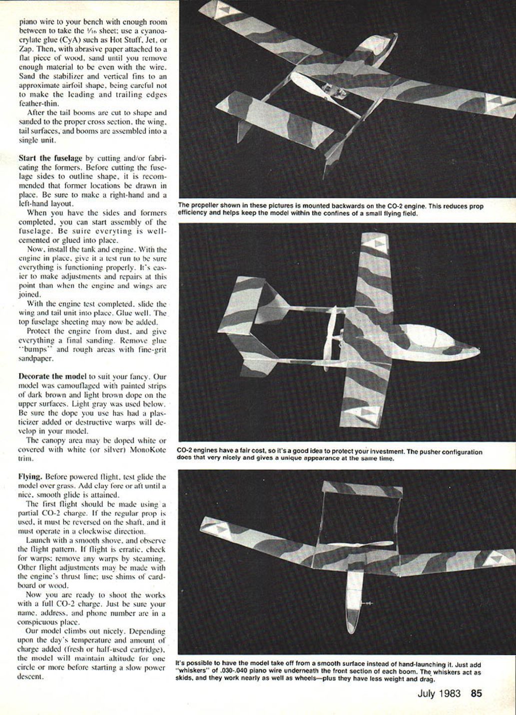
- The propeller shown in photos was mounted "backwards" (reduced efficiency) to help keep the model within a small flying field — useful where confinement is needed.
- CO-2 engines can be relatively costly; the pusher layout helps protect the engine in nose-first impacts.
- To enable ground takeoffs from smooth surfaces, add whiskers of .030–.040" piano wire under the front boom section; they act as lightweight skids, nearly as effective as wheels with less weight and drag.
- This is a straightforward sheet-balsa free-flight model that yields satisfying results and a realistic pusher appearance derived from a plausible full-scale concept.
Transcribed from original scans by AI. Minor OCR errors may remain.

