
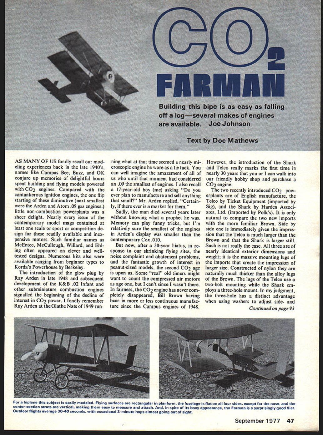
CO2 FARMAN
Building this bipe is as easy as falling off a log—several makes of engines are available. Joe Johnson
Text by Doc Mathews
AS MANY OF US fondly recall our modeling experiences back in the late 1940's, names like Campus Bee, Buzz, and OK conjure up memories of delightful hours spent building and flying models powered with CO2 engines. Compared with the cantankerous ignition engines, the one flip starting of these diminutive (next smallest were the Arden and Atom .09 gas engines) little non-combustion powerplants was a sheer delight. Nearly every issue of the contemporary model mags contained at least one scale or sport or competition design for these readily available and inexpensive motors. Such familiar names as McEntee, McCullough, Willard, and Ehling often appeared on clever and well-tested designs. Numerous kits also were available ranging from beginner types to Korda's Powerhouse by Berkeley.
The introduction of the glow plug by Ray Arden in late 1948 and subsequent development of the K&B .02 Infant and other subminiature combustion engines signaled the beginning of the decline of interest in CO2 power. I fondly remember Ray Arden at the Olathe Nats of 1949 running what at that time seemed a nearly microscopic engine he wore as a tie tack. You can well imagine the amazement of all of us who until that moment had considered an .09 the smallest of engines. I also recall a 17-year-old boy (me) asking "Do you ever plan to manufacture and sell anything that small?" Mr. Arden replied, "Certainly, if there ever is a market for them."
Sadly, the man died several years later without knowing what a prophet he was. Memory can play funny tricks, but I'm relatively sure the smallest of the engines in Arden's display was smaller than the contemporary Cox .010.
But now, after a 30-year hiatus, in response to our shrinking flying sites, the noise complaint and abatement problems, and the fantastic growth of interest in peanut-sized models, the second CO2 age is upon us. Some "real" old timers might want to count the compressed air motors as age one, but I can't since I wasn't there. In fairness, the CO2 engine has never completely disappeared, Bill Brown having been in more or less continuous manufacture since the Campus engines of 1948.
However, the introduction of the Shark and Telco really marks the first time in nearly 30 years that you or I can walk into our friendly hobby shop and purchase a CO2 engine.
The two recently introduced CO2 powerplants are of English manufacture, the Telco by Ticket Equipment (imported by Sig), and the Shark by Harden Associates, Ltd. (imported by Polk's). It is only natural to compare the two new imports with the more familiar Brown. Side by side one is immediately given the impression that the Telco is much larger than the Brown and that the Shark is larger still. Such is not really the case. All three are of nearly identical exterior dimensions and weight; it is the massive mounting lugs of the imports that create the impression of larger size. Constructed of nylon they are naturally much thicker than the alloy lugs of the Brown. The lugs of the Telco use a two-bolt mounting while the Shark employs a three-hole mount. In my judgment, the three-hole has a distinct advantage when using washers to adjust side- down-thrust.
The Shark also differs in the use of a metal cylinder of considerably larger diameter than the nylon one of the Telco, a prop nut rather than a bolt as on the Telco, and a plated tank. Both powerplants utilize a charging gun which fits snugly onto a nipple-type fitting. Early on the Telco nipple was all nylon but more recent examples have a metal fitting for the charging gun, as does the Shark.
The principal mechanical difference between the three engines is the method of speed control. All three use poppet valves to admit the gas, opening as the piston strikes them at top dead center. Speed is proportional to how far the poppet is displaced. The more gas admitted the faster the rpm and the shorter the duration. The Brown and Shark engines adjust the CO2 volume by screwing the cylinder up and down, whereas the Telco crankshaft is mounted in an eccentric bearing. The crankshaft bearing is rotated with a knurled aluminum flange located immediately behind the prop. Raising or lowering the shaft corresponds remarkably to advancing or retarding the spark lever on old ignition engines.
The Model
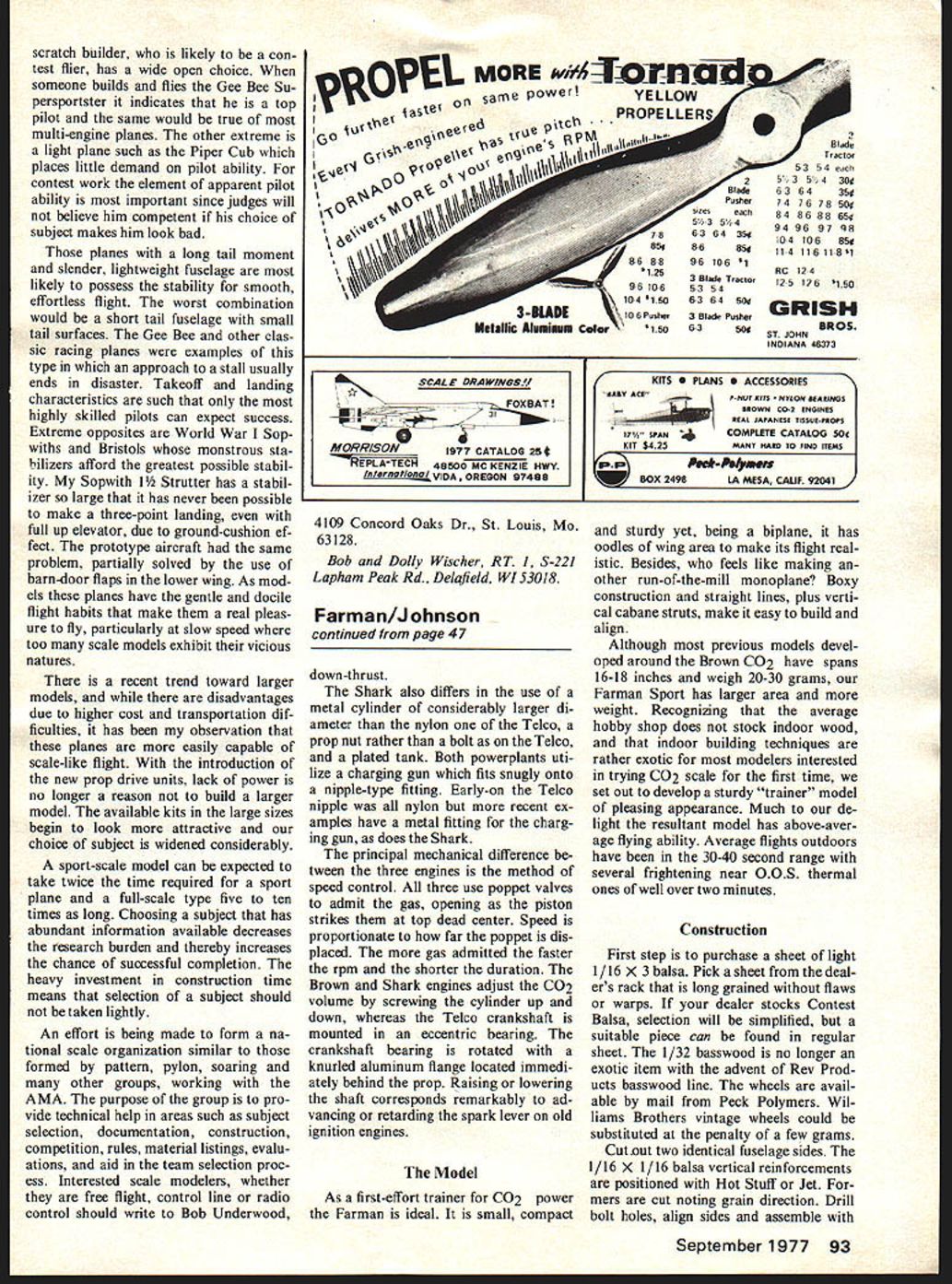
As a first-effort trainer for CO2 power the Farman is ideal. It is small, compact and sturdy yet, being a biplane, it has oodles of wing area to make its flight realistic. Besides, who feels like making another run-of-the-mill monoplane? Boxy construction and straight lines, plus vertical cabane struts, make it easy to build and align.
Although most previous models developed around the Brown CO2 have spans 16-18 inches and weigh 20-30 grams, our Farman Sport has larger area and more weight. Recognizing that the average hobby shop does not stock indoor wood, and that indoor building techniques are rather exotic for most modelers interested in trying CO2 scale for the first time, we set out to develop a sturdy "trainer" model of pleasing appearance. Much to our delight the resultant model has above-average flying ability. Average flights outdoors have been in the 30-40 second range with several frightening near O.O.S. thermal ones of well over two minutes.
Construction
First step is to purchase a sheet of light 1/16 x 3 balsa. Pick a sheet from the dealer's rack that is long grained without flaws or warps. If your dealer stocks Contest Balsa, selection will be simplified, but a suitable piece can be found in regular sheet. The 1/32 basswood is no longer an exotic item with the advent of Rev Products basswood line. The wheels are available by mail from Peck Polymers. Williams Brothers vintage wheels could be substituted at the penalty of a few grams.
Cut out two identical fuselage sides. The 1/16 x 1/16 balsa vertical reinforcements are positioned with Hot Stuff or Jet. Formers are cut noting grain direction. Drill bolt holes, align sides and assemble with Sig Bond. Use a triangle and carpenter's square to check, holding everything in position with masking tape. Allow several hours for resin to set then pull tail post together, using fast glue. The 1/32 balsa fairing is positioned, formed, and instant-glued in place. (A Sig cowl is shown.) The gear is bent to shape over the plan, then attached to a 1/16 ply former with carpet thread, wrapped, and glued.
Tail surfaces are cut from 1/16 sheet, sanded, and positioned with fast glue. Scallops can be easily done with sandpaper on a 1/4" dowel.
The wing is straight-forward, involving two identical assemblies with the center section cut out and discarded for the lower wing. Dihedral angle is sanded in, using a 1/8-in. block under tip and the classic table edge. Joints are fast glued. Cover and finish wings before attaching them to fuselage. Japanese tissue and clear dope works fine.
The engine and its hardware should be installed before covering the fuselage. A handy removable motor set-up can be made by epoxying the nuts onto a small piece of plywood, which is fast glued to the back of the firewall. The filler nipple is mounted on 1/32 ply and stuck in position after rolling the tubing in loops as needed to place the tank in the proper position. Use a scrap of balsa to hold tank tight.
The finish on the prototype was done with Floquil Caboose Red mixed in clear nitrate dope. Although an airbrush would be ideal, the color was brushed on. One coat covered well and added almost no weight. Do not attempt to use colored dope; it is much too heavy.
Now cut the cabanes from 1/32 ply. Mark the exit point from fuselage side (in pencil, not ball-point) and entry at rib bottom. Cut thin slots through the 1/32 balsa cowl, stick cabane through, and fasten with fast glue. The tissue is cut in the wing center section and the top wing positioned with fast glue, checking alignment carefully. The lower wing is installed in the same way, then the 1/32 bass interplane struts are installed with fast glue.
The model is completed by constructing the 1/32 bass landing gear frame in place on the fuselage bottom. The wire is not attached to the basswood. It is allowed to swing free, preventing breakage but still looking realistic. The tailskid is cut from basswood and fast glued to the tail post. Interplane "wires" are monofilament fishing line threaded through the small holes previously drilled in the struts. Tie a knot in one end, thread through both holes, tighten and fast glue. The wires should be tightened only enough to remove sag. They are not functional.
Transcribed from original scans by AI. Minor OCR errors may remain.

