
Comedian
Henry Farrell
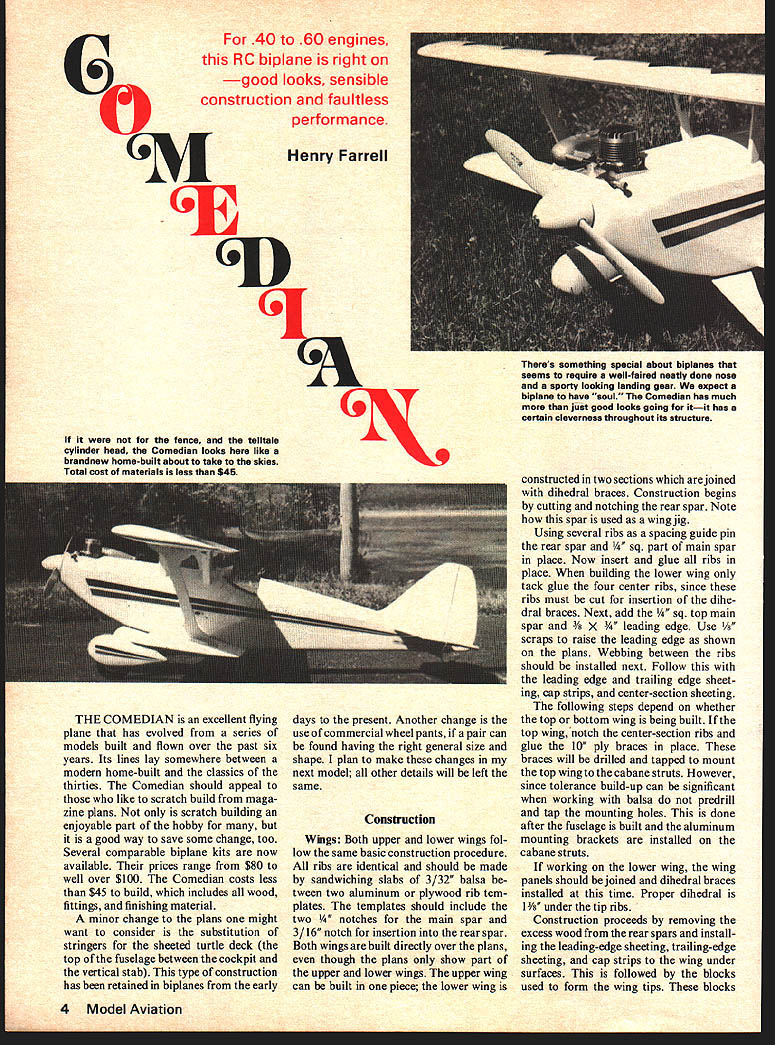
THE COMEDIAN is an excellent flying plane that has evolved from a series of models built and flown over the past six years. Its lines lay somewhere between a modern home-built and the classics of the thirties. The Comedian should appeal to those who like to scratch build from magazine plans. Not only is scratch building an enjoyable part of the hobby for many, but it is a good way to save some change, too. Several comparable biplane kits are now available. Their prices range from $80 to well over $100. The Comedian costs less than $45 to build, which includes all wood, fittings, and finishing material.
A minor change to the plans one might want to consider is the substitution of stringers for the sheeted turtle deck (the top of the fuselage between the cockpit and the vertical stab). This type of construction has been retained in biplanes from the early days to the present. Another change is the use of commercial wheel pants, if a pair can be found having the right general size and shape. I plan to make these changes in my next model; all other details will be left the same.
Construction
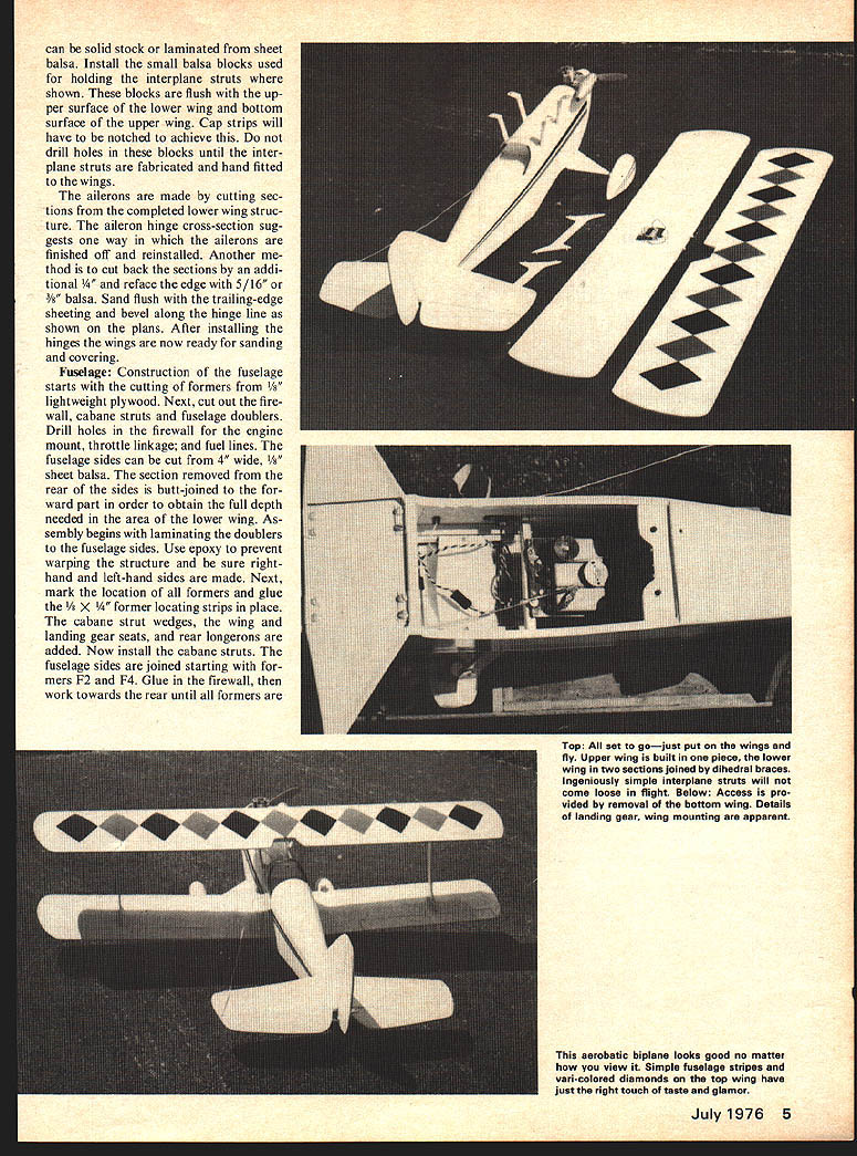
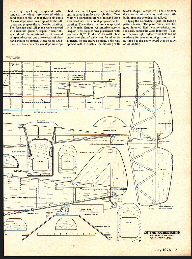
Wings: Both upper and lower wings follow the same basic construction procedure. All ribs are identical and should be made by sandwiching slabs of 3/32" balsa between two aluminum or plywood rib templates. The templates should include the two 1/4" notches for the main spar and 3/16" notch for insertion into the rear spar. Both wings are built directly over the plans, even though the plans only show part of the upper and lower wings. The upper wing can be built in one piece; the lower wing is constructed in two sections which are joined with dihedral braces. Construction begins by cutting and notching the rear spar. Note how this spar is used as a wing jig.
Using several ribs as a spacing guide, pin the rear spar and 1/4" sq. part of main spar in place. Now insert and glue all ribs in place. When building the lower wing only, tack glue the four center ribs, since these ribs must be cut for insertion of the dihedral braces. Next, add the 1/4" sq. top main spar and 3/8" x 1/4" leading edge. Use 1/8" scraps to raise the leading edge as shown on the plans. Webbing between the ribs should be installed next. Follow this with the leading edge and trailing edge sheeting, cap strips, and center-section sheeting.
The following steps depend on whether the top or bottom wing is being built. If the top wing, notch the center-section ribs and glue the 1/8" ply braces in place. These braces will be drilled and tapped to mount the top wing to the cabane struts. However, since tolerance build-up can be significant when working with balsa, do not predrill and tap mounting holes until after the fuselage is built and the aluminum mounting brackets are installed on the cabane struts.
If working on the lower wing, the wing panels should be joined and dihedral braces installed at this time. Proper dihedral is 1 1/8" under the tip ribs.
Construction proceeds by removing the excess wood from the rear spars and installing the leading-edge sheeting, trailing-edge sheeting, and cap strips to the wing under surfaces. Blocks are then used to form the wing tips. These blocks are sanded and faired to shape before installing the wing tip sheeting. can be solid stock or laminated from sheet balsa. Install the small balsa blocks used for holding the interplane struts where shown. These blocks are flush with the upper surface of the lower wing and bottom surface of the upper wing. Cap strips will have to be notched to achieve this. Do not drill holes in these blocks until the interplane struts are fabricated and hand fitted to the wings.
The ailerons are made by cutting sections from the completed lower wing structure. The aileron hinge cross-section suggests one way in which the ailerons are finished off and reinstalled. Another method is to cut back the sections by an additional 1/4" and reface the edge with 5/16" or 3/8" balsa. Seal flush with the trailing-edge sheeting and bevel along the hinge line as shown on the plans. After installing the hinges the wings are now ready for sanding and covering.
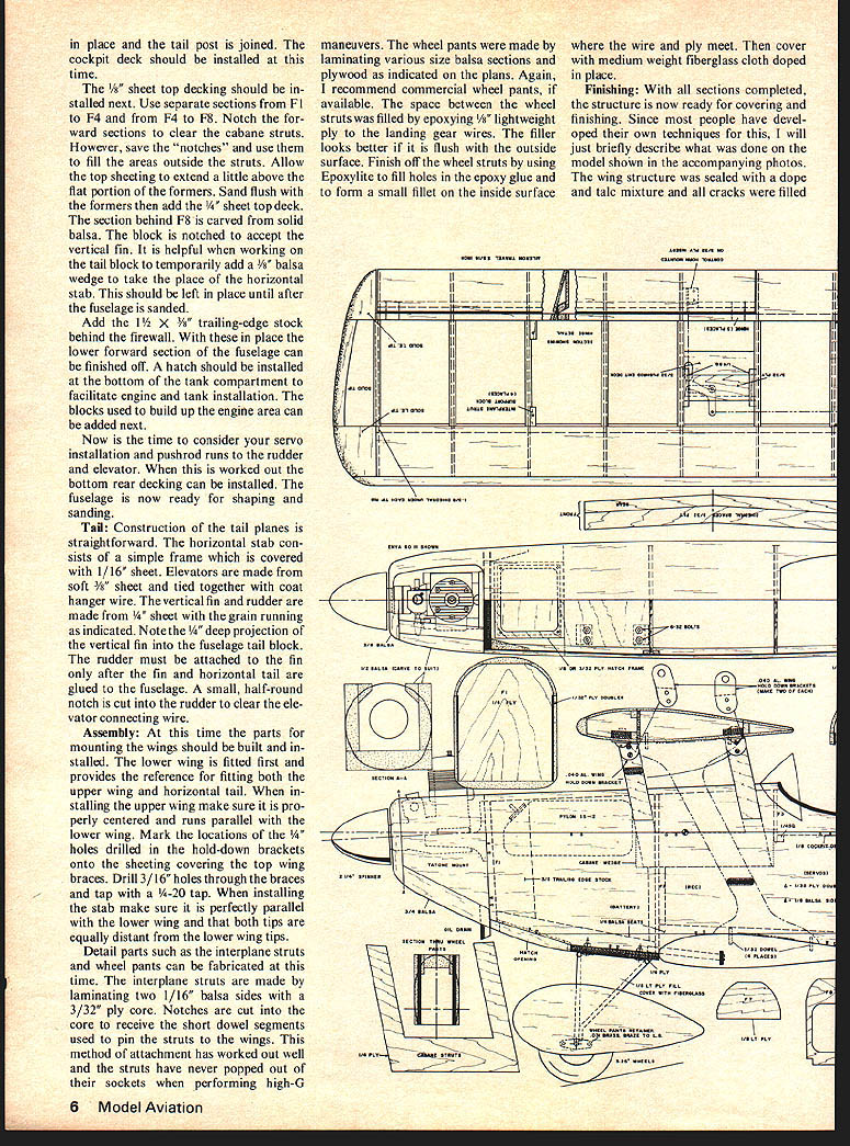
Fuselage: Construction of the fuselage starts with the cutting of formers from 1/8" lightweight plywood. Next, cut out the firewall, cabane struts and fuselage doublers. Drill holes in the firewall for the engine mount, throttle linkage, and fuel lines. The fuselage sides can be cut from 4" wide, 1/8" sheet balsa. The section removed from the rear of the sides is butt-joined to the forward part in order to obtain the full depth needed in the area of the lower wing. Assembly begins with laminating the doublers to the fuselage sides. Use epoxy to prevent warping the structure and be sure right-hand and left-hand sides are made. Next, mark the location of all formers and glue the 1/8" x 1/4" former locating strips in place. The cabane strut wedges, the wing and landing gear seats, and rear longerons are added. Now install the cabane struts. The fuselage sides are joined starting with formers F2 and F4. Glue in the firewall, then work towards the rear until all formers are glued in. in place and the tail post is joined. The cockpit deck should be installed at this time.
The 1/8" sheet top decking should be installed next. Use separate sections from F1 to F4 and from F4 to F8. Notch the forward sections to clear the cabane struts. However, save the "notches" and use them to fill the areas outside the struts. Allow the top sheeting to extend a little above the flat portion of the formers. Sand flush with the formers then add the 1/4" sheet top deck.
The section behind F8 is carved from solid balsa. The block is notched to accept the vertical fin. It is helpful when working on the tail block to temporarily add a 1/8" balsa wedge to take the place of the horizontal stab. This should be left in place until after the fuselage is sanded.
Add the 1/2" x 5/8" trailing-edge stock behind the firewall. With these in place the lower forward section of the fuselage can be finished off. A hatch should be installed at the bottom of the tank compartment to facilitate engine and tank installation. The blocks used to build up the engine area can be added next.
Now is the time to consider your servo installation and pushrod runs to the rudder and elevator. When this is worked out the bottom rear decking can be installed. The fuselage is now ready for shaping and sanding.
Tail
Construction of the tail planes is straightforward. The horizontal stab consists of a simple frame which is covered with 1/16" sheet. Elevators are made from soft 3/32" sheet and tied together with coat hanger wire. The vertical fin and rudder are made from 1/4" sheet with the grain running as indicated. Note the 1/4" deep projection of the vertical fin into the fuselage tail block. The rudder must be attached to the fin only after the fin and horizontal tail are glued to the fuselage. A small, half-round notch is cut into the rudder to clear the elevator connecting wire.
Assembly
At this time the parts for mounting the wings should be built and installed. The lower wing is fitted first and provides the reference for fitting both the upper wing and horizontal tail. When installing the upper wing make sure it is properly centered and runs parallel with the lower wing. Mark the locations of the 1/4" holes drilled in the hold-down brackets onto the sheeting covering the top wing braces. Drill 3/16" holes through the braces and tap with a 4-20 tap. When installing the stab make sure it is perfectly parallel with the lower wing and that both tips are equally distant from the lower wing tips.
Detail parts such as the interplane struts and wheel pants can be fabricated at this time. The interplane struts are made by laminating two 1/16" balsa sides with a 3/32" ply core. Notches are cut into the core to receive the short dowel segments used to pin the struts to the wings. This method of attachment has worked out well and the struts have never popped out of their sockets when performing high-G maneuvers. The wheel pants were made by laminating various size balsa sections and plywood as indicated on the plans. Again, I recommend commercial wheel pants, if available. The space between the wheel struts was filled by epoxying 1/8" lightweight ply to the landing gear wires. The filler looks better if it is flush with the outside surface. Finish off the wheel struts by using Epoxylite to fill holes in the epoxy glue and to form a small fillet on the inside surface where the wire and ply meet. Then cover with medium weight fiberglass cloth doped in place.
Finishing
With all sections completed, the structure is now ready for covering and finishing. Since most people have developed their own techniques for this, I will just briefly describe what was done on the model shown in the accompanying photos. The wing structure was sealed with a dope and tack mixture and all cracks were filled. sides with vinyl spackling compound. After sanding, the wings were covered with a good grade of silk. About five to six coats of clear dope were then applied to the silk to seal and prepare the surface for painting.
The fuselage and tail plane were covered with medium grade Silkspan. Since Silkspan should be moistened to fit around compound curves, one or two coats of clear dope should be applied to the wood structure first. Six coats of clear dope were applied over the Silkspan, then wet sanded until a smooth surface was obtained. Two coats of a thinned mixture of talc and dope were used next as a final preparation for painting. The entire structure was sprayed with Martin Senour Automotive acrylic lacquer. The lacquer was plasticized with Southern R/C Products' Flex-All. Just under one pint of paint was found to be sufficient for the entire airplane. Trim was applied with a brush after masking with Scotch Magic Transparent Tape. This tape does not require sealing and very little build-up along the edges is realized.
Flying the Comedian is just like flying a pattern trainer. The plane tracks well, has good inverted flight characteristics, and can easily handle the Class B pattern. Takeoff requires right rudder to be held but no tendency for ground looping is present. At no time has the plane nosed over on takeoff or landing.
Transcribed from original scans by AI. Minor OCR errors may remain.

