
Comet Jr. Clipper + 35%
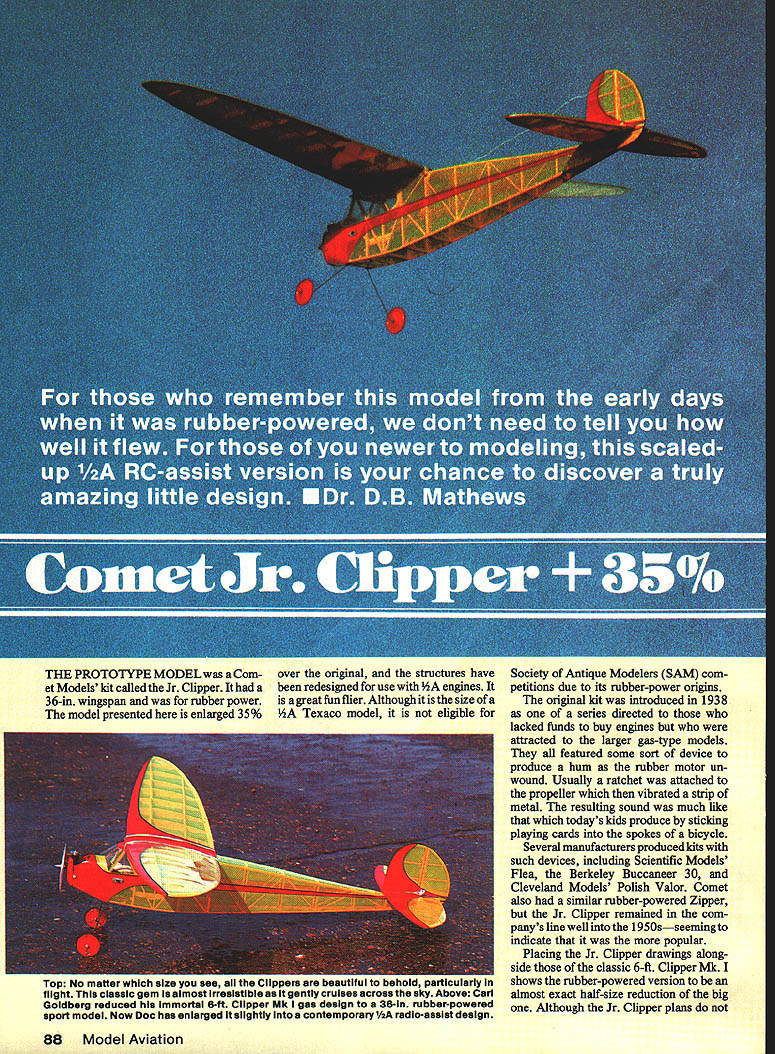
The prototype model was a Comet Models kit called the Jr. Clipper. It had a 36-in. wingspan and was originally rubber‑powered. The model presented here is enlarged 35% over the original, and the structures have been redesigned for use with 1/2A engines. It is a great fun flier. Although it is the size of a 1/2A Texaco model, it is not eligible for Society of Antique Modelers (SAM) competitions because of its rubber‑power origins.
The original kit was introduced in 1938 as one of a series directed to those who lacked funds to buy engines but who were attracted to the larger gas‑type models. The rubber models often featured a device to produce a hum as the rubber motor unwound — usually a ratchet attached to the propeller that vibrated a strip of metal. The resulting sound was much like kids sticking playing cards into the spokes of a bicycle.
Several manufacturers produced kits with such devices, including:
- Scientific Models' Flea
- Berkeley Buccaneer 30
- Cleveland Models' Polish Valor
Comet also had a similar rubber‑powered Zipper, but the Jr. Clipper remained in the company's line well into the 1950s, indicating it was the more popular design.
Placing the Jr. Clipper drawings alongside those of the classic 6‑ft. Clipper Mk I shows the rubber‑powered version to be an almost exact half‑size reduction of the big one. The enlarged version is a contemporary 1/2A radio‑assist design. The designer genius of Carl Goldberg is obvious: the enlarged Jr. Clipper retains the aesthetic beauty of the big Clipper with lovely elliptical planform lines while simplifying many structures. The wing uses a flat‑bottom airfoil with simple spars and a flat stabilizer — no need to cut a lot of ribs — yet the model possesses better‑than‑average wind penetration and performs well in thermals and light lift.
Construction
Wood sizes chosen are close to the minimum adequate for structural integrity. The fuselage could be built of 1/8-in. sq. balsa instead of the specified 3/16-in., but 3/16-in. weighs very little more and, especially with corners sanded round, provides rigidity and aids boxing steps.
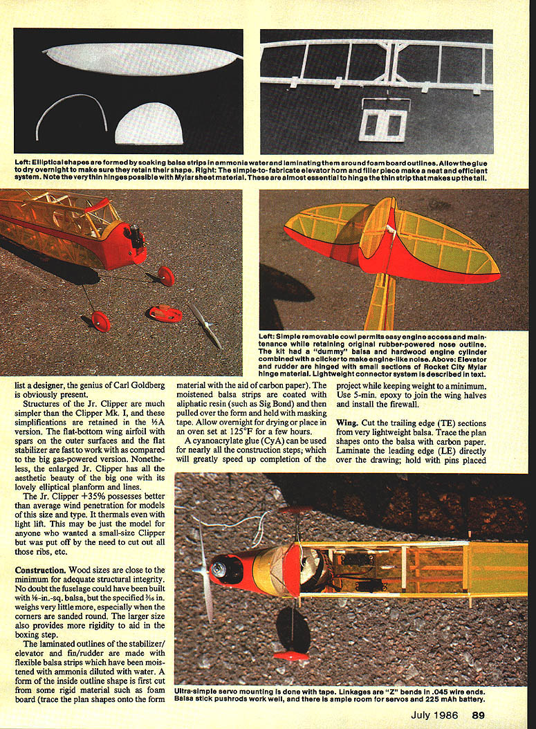
Laminated outlines for stabilizer/elevator and fin/rudder are made from flexible balsa strips moistened with ammonia‑diluted water and formed inside an outline form. First cut some rigid material such as foam board and trace the plan shapes onto the form material (use carbon paper to aid tracing). Moistened balsa strips coated with an aliphatic resin such as Sig Bond are pulled over the form and held with masking tape. Allow overnight drying; you may also place the form in an oven set to 125°F for a few hours.
Cyanoacrylate glue (CyA) can be used for many construction steps; it speeds completion and keeps weight to a minimum. Use 5‑minute epoxy to join the wing halves and install the firewall.
Wing
- Cut trailing‑edge (TE) sections from very lightweight balsa. Trace plan shapes onto the balsa with carbon paper.
- Laminate the leading edge (LE) directly over the drawing and hold with pins to form the shape. Elliptical shapes are formed by soaking balsa strips in ammonia water and laminating around foam‑board outlines. Allow the glue to dry overnight to ensure the shape is retained.
- Build the wing completely flat on the building board with the top spars pulled down at the tips. No tapering spars are required.
- Add shear webs in front of the spars while the wing is on the building board to prevent warping.
- After both wing halves are built, use the pre‑tilted center section ribs, block up each tip to dihedral height, and block‑sand the proper bevel using a square edge on the building board.
- Join the two halves with 5‑minute epoxy; clamp the center ribs together with clothespins.
- Add the center section strips and a 1/32‑ply dihedral gusset if desired (the prototype did not have a gusset and survived spins without damage).
- Sand the LE and TE to the contour shown on the plans either before or after setting the dihedral. When covering the wing, shrink both sides of a panel equally to help prevent warps.
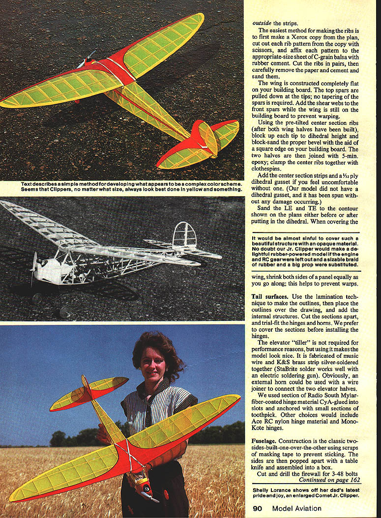
It would be almost sinful to cover such a beautiful structure with an opaque material — the Jr. Clipper would also make a delightful rubber‑powered model if engine and R/C gear were left out in favor of a braid of rubber and a big prop.
Tail surfaces
- Use the lamination technique to make the outlines, then place the outlines over the drawings and add the internal structures.
- Cut sections apart and trial‑fit hinges and horns. Prefer to cover the sections before installing the hinges.
- The elevator "tiller" is not required for performance but improves appearance. Fabricate it from music wire and K&S brass strip silver‑soldered together (StaBrite solder works well with an electric soldering gun). An external horn with a wire joiner can be used to connect the two elevator halves.
- The prototype used Radio South Mylar‑fiber‑coated hinge material, CyA‑glued into slots and anchored with small sections of toothpick. Other choices include Ace RC nylon hinge material or MonoKote hinges.
Fuselage
- Construct the fuselage by building two sides on the board, one over the other, using scraps of masking tape to prevent sticking. Pop the sides apart with a table knife and assemble into a box.
- Cut and drill the firewall for 3‑48 bolts and blind nuts. Do not mount the engine with screws. Fabricate jigs 1 and 2 directly over the drawing. Part FB is 1/16‑in. ply and should be drilled to accept the already‑bent landing gear unit.
- Place the left frame over the plan and weight it down. Install the two jigs in their appropriate slots, checking for absolute squareness in both planes (use a carpenter's square or 90° triangle).
- CyA‑glue the jigs to the left side, then place the right side over them; check alignment and CyA‑glue the right side to the jigs.
- Pull the tail posts together and hold with clothespins while checking for squareness, then CyA‑glue them together.
- Cut the cross braces in pairs using the top view as a guide and install them from front to back to produce a well‑aligned fuselage box.
- Remove the box from the building board and install the firewall using the top view as a guide. Install the landing gear, followed by Bulkheads C and D. Finish the fuselage by adding front sheeting and nose blocks; sand to a nice contour.
Jr. Clipper/Mathews
Apply the first coat of polyurethane varnish and let it dry thoroughly. Finish‑sand the polyurethane with 320‑grit paper and apply a second coat. When the box is dry, install all hardware and covers. To ensure small hinge screws will hold, squirt some Zap‑A‑Gap into the screw holes before assembly.
Cut and slit pipe‑insulation material for airplane support slots in the cover. Cut and Zap‑glue foam rubber into the transmitter and fuel can cavities. Mount the handle, axle, and wheels to ensure they fit properly; you may need to trim excessive polyurethane from mounting holes.
(An aside: the first time you use your Flight Assistant or flight box at the field, expect ribbing from fellow modelers — but soon they'll be asking for plans or requesting you build one for them.)
Radio installation
- The prototype came out slightly under 18 oz. with a 100 mAh battery; this indicates micro servos are not strictly required. Our servos were mounted to Lite Ply rails with servo tape. If the wood is first hardened with a coat of CyA, the tape will stick without pulling loose from the grain.
- The plan details a simple, lightweight pushrod system. Available flex‑rods are usually too heavy for this type of model.
- With the elevator horn buried, carefully set the servo end Z‑bend for neutral before final placement; some adjustment is available by repositioning the servo.
- In our setup we placed a 225 mAh battery against the firewall, the Royal Vanguard receiver wrapped in foam immediately behind it, and the servos almost directly under the center of gravity (CG). No ballast was required.
Control throws
Control throws on a model with a wide speed differential from power on to power off are largely a matter of pilot skill. If you have dual‑rate for elevator and rudder, use minimum throws for power, then switch to higher throws for the glide.
Suggested throws:
- Rudder: 1 in. total (measured at the widest point)
- Elevator: 3/4 in. total (measured at the widest point)
These are gentle settings for powered flight; use a gentle thumb during the powered portion and increase for glide as needed.
Another variable is engine tuning approach for Old‑Timer‑like R/C‑assist flying:
- Some use two head gaskets with 5% nitro fuel and an 8x3 prop for a long, low‑powered run.
- Others prefer 30% nitro and a 6x3 prop to get up quickly.
Which you choose will affect desirable control throw amounts.
Covering and decorating
- The prototype was covered with MonoKote. Tissue and clear dope would be lighter and are a viable choice if you use larger radio equipment.
- Trace the decoration outlines of the original kit by placing covered sections over the plans and tracing through the transparent covering with a pencil designed for Mylar (e.g., Dixon Vis‑a‑Vis 38).
- An adjustable French curve helps develop steady, smooth curves. Use the upper outlines as guides when tracing bottom surfaces.
- Sig Stripe Rite tape in 3/32‑in. or 1/8‑in. widths flexes well around curves and can be widened later with electrician's tape. Seal edges with a clear product such as Sig Skybrite applied along seams to prevent seepage.
- Use paper and masking tape to mask areas not to be painted. Lightly score MonoKote with #400 steel wool to remove some gloss, clean with acetone, and avoid touching surfaces afterward.
- Poly‑Oil spray was used on the prototype: after shaking the can, apply a light mist from 12 in. or more away for a semi‑transparent color. Remove masking and reapply fresh Stripe Rite trim lines as needed.
- Prime and spray the engine compartment and removable cowl front separately with Skybrite primer.
Flying
A problem with many models of this type is inadequate wind penetration: some won't turn downwind, others climb straight up without moving forward, and some glide poorly in calm air. Wing loading and CG placement should be selected according to typical wind velocity. The CG point shown on the plans is for windy conditions; move it rearward 1/8 in. to 3/16 in. for light winds.
For some reason the Jr. Clipper +35% behaves better in the wind than other Jr. types. Perhaps the wide fuselage profile, tapered flat‑bottom airfoil, or longer‑than‑average tail moment helps. The model penetrates well, will turn upwind or downwind with ease, and will float in light lift.
Hand launches are well controlled, with only a slight tendency to veer or drop. The Jr. Clipper +35% tends to climb on its wing rather than on the prop, producing a straight out‑and‑up climb instead of a corkscrew. Slow‑speed characteristics are excellent; gentle, well‑placed landings are easy even in wind. All in all, this is a very nice little airplane.
Transcribed from original scans by AI. Minor OCR errors may remain.

