
Competitor II
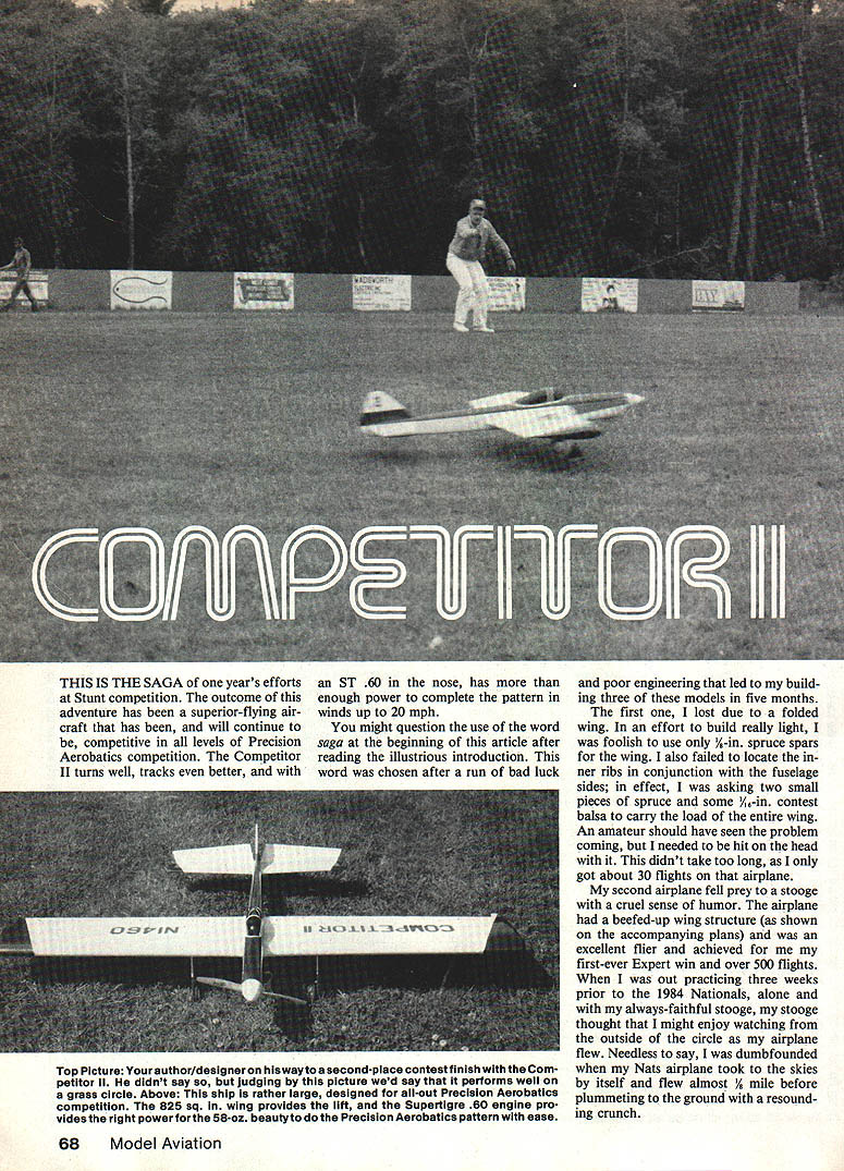
This is the saga of one year's efforts at Stunt competition. The outcome of this adventure has been a superior-flying aircraft that has been, and will continue to be, competitive in all levels of Precision Aerobatics competition. The Competitor II turns well, tracks even better, and with an ST .60 in the nose, has more than enough power to complete the pattern in winds up to 20 mph.
You might question the use of the word "saga" after reading the illustrious introduction. That word was chosen after a run of bad luck and poor engineering that led me to build three of these models in five months. The first one I lost due to a folded wing. In an effort to build really light, I was foolish to use only 1/16-in. spruce spars for the wing. I also failed to locate the inner ribs in conjunction with the fuselage sides; in effect, I was asking two small pieces of spruce and some 1/16-in. contest balsa to carry the load of the entire wing. An amateur should have seen the problem coming, but I needed to be hit on the head with it. This didn't take too long, as I only got about 30 flights on that airplane.
My second airplane fell prey to a stooge with a cruel sense of humor. That airplane had a beefed-up wing structure (as shown on the accompanying plans), was an excellent flier, and achieved for me my first-ever Expert win and over 500 flights. When I was out practicing three weeks prior to the 1984 Nationals, alone and with my always-faithful stooge, my stooge thought I might enjoy watching from the outside of the circle as my airplane flew. Needless to say, I was dumbfounded when my Nats airplane took to the skies by itself and flew almost 1/2 mile before plummeting to the ground with a resounding crunch.
Design theory
Some definite goals: I sat down last fall to design a new airplane for the following year. I wanted an airplane that would turn in blinding corners, track well, penetrate the wind, and give the line tension that might be needed.
- To solve the blinding-turn problem I went with what I thought would be a significant contribution — an extremely light wing loading. The first airplane weighed 49 oz., giving a wing loading of about 8.5 oz./sq ft. Lighter than the average competition sailplane, the airplane would surely turn but it sacrificed structural integrity; during the building phase the wing didn't hold up.
- The next airplane weighed 57 oz., due to a partially beefed-up wing. I rushed the building job and unnecessary weight was added; lacking suitable contest balsa resulted in a wing loading of about 10.1 oz./sq ft. That loading provided a very acceptable turn while giving the ship sufficient structural integrity. The stooge let go and that airplane put approximately 175 flights on in six weeks.
To make the airplane track well, the nose is fairly long to take advantage of the stabilizing effect of the propeller. Combined with a good-sized tail moment, this provides a damping effect. The center of gravity (CG) is located well rearward, as shown on the plans. I prefer to fly airplanes with the CG well rearward — almost to the point of being tail-heavy — to get maneuverability out of a nice, stable ship. A forward-located CG is great for a sport flier, racer, or anything expected to maintain level flight throughout the entire circle. But if you ask the airplane to perform a violent set of maneuvers, such as the Precision Aerobatics pattern, a rearward CG will optimize aerodynamic properties and make performance — overpower the model! I could always add wing area and raise the wing loading, but that would decrease the responsiveness I wanted. Instead, I chose power.
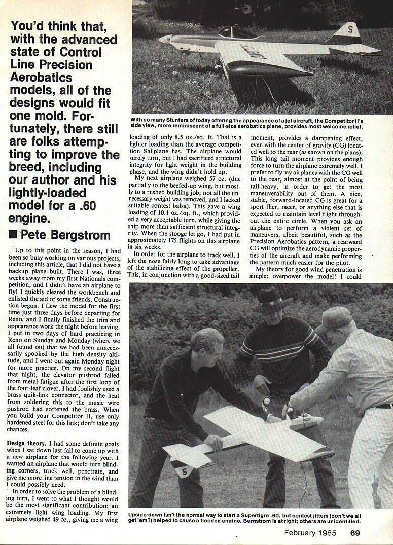
Although the judging picture doesn't say much, the Competitor II performs well in the grass circle. The ship is rather large — designed all-out for Precision Aerobatics competition. The 825 sq. in. wing provides lift, and the Super Tigre .60 engine provides the right power for the 58-oz. beauty to fly the Precision Aerobatics pattern with ease.
I could have sharpened the leading edge, but that would have degraded the turning ability and created an early stall point. Therefore, I opted to go with a thick wing section and blunt nose to allow the airplane to perform to my expectations and simply put in enough horsepower to bully my way through the overhead figures of the pattern in wind. The ST .60 was not chosen because of brute horsepower (an O.S. Max .45 has more peak horsepower than the ST .60), but rather because it has more usable power (torque) at the speed that stunt fliers like to run their engines. The size of the Competitor II allows me to run 13-in. props without the associated yaw problems common with large propellers — and in calm conditions, 14-in. props as well. This does wonders for line tension as well as turning that usable power into wind penetration.
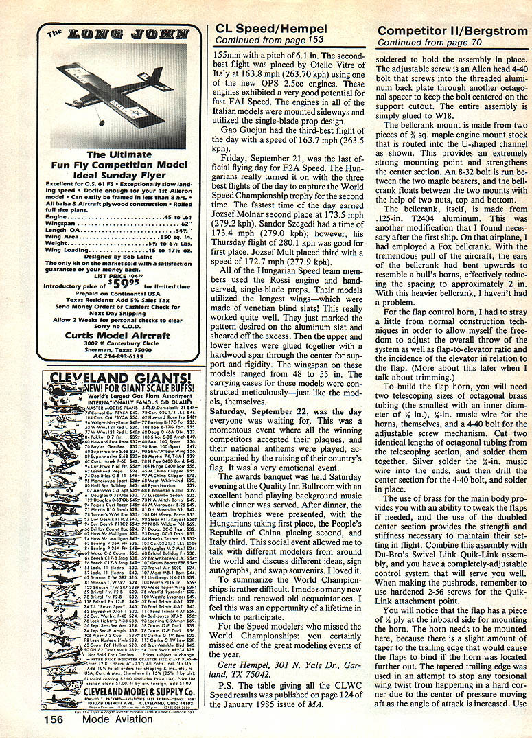
While on the subject of line tension: I have not included a movable rudder on this plane, nor is there any rudder offset. The only time you need either of these features is when you build a crooked fuselage. On a straight fuselage, rudder trim adds an unwanted yawing motion that makes trimming the model for all phases of flight more difficult.
Line tension comes from engine power. True, by adjusting the lead-outs you can provide some tension in certain parts of the pattern (but you cannot manufacture line tension by this method). Likewise, adding tip weight can improve the tension on top, but you will not be able to avoid dropping a wing in a good, hard corner if you lack basic line tension from the airframe/powerplant combination. It's simple: if you don't have the line tension in the basic airframe/powerplant combination, you will never manufacture it and will always have to settle for a compromised situation at best.
Construction
Although this airplane is not all that difficult to build, it is not designed for a beginner. It is intended for the expert flier who wants an edge on competitors, or the advanced flier looking to move into the expert ranks. I will not include a blow-by-blow construction description; instead, I'll highlight the important points.
Wing
The wing is basic D-tube construction. The landing gear blocks are secured with 1/8-in. ply doublers to ribs W4 and W6.
The lead-out guide is constructed from aluminum and brass. The support piece is 1/8-in. aluminum with a center cutout for slider movement. The individual guides use 1/16-in. aluminum for a back plate, a brass eyelet for the wire to pass through, a piece of octagonal brass tubing as a spacer to run in the cutout of the support piece, and a washer that is slid over the eyelet and crimped to hold the assembly in place. The adjustable screw is an Allen-head 4-40 bolt that screws into the threaded aluminum back plate through another octagonal spacer to keep the bolt centered on the support cutout. The entire assembly is glued to rib W18.
The bellcrank mount is made from two pieces of 3/32-in. square maple engine-mount stock routed into the U-shaped channel as shown on the plans. This provides an extremely strong mounting point and strengthens the center section. An 8-32 bolt runs between the two maple bearers, and the bellcrank floats between the two mounts with the help of two nuts, top and bottom. The bellcrank itself is made from .125-in. T2404 aluminum. This was a modification I found necessary after the first ship. On that airplane I had employed a Fox bellcrank; with the tremendous pull of the aircraft the ears of the bellcrank had bent upwards, effectively reducing the spacing to approximately 2 in. between the horns. With this heavier bellcrank, I haven't had that problem.
For the flap control horn I had to stray a little from normal construction techniques to allow freedom to adjust the overall throw of the surfaces, the flap-to-elevator ratio, and the incidence of the elevator relative to the flap.
To build the flap horn you will need two telescoping sizes of octagonal brass tubing (the smaller with an internal 1/16-in. music wire for the horn) and a 4-40 bolt for the adjustable screw mechanism. Cut two identical lengths of octagonal tubing from the telescoping section and silver-solder them together. Silver-solder the 1/16-in. music wire into the ends, then drill the center section for the 4-40 bolt and solder it in place.
Using brass for the main body allows you to tweak the flaps if needed, and the double center section provides the strength and stiffness necessary to maintain their setting in flight. Combine this assembly with Du-Bro's Swivel Link Quik-Link assembly, and you have a completely adjustable control system. When making the pushrods, remember to use hardened 2-56 screws for the Quik-Link attachment point.
The flap has a piece of 1/4-in. ply at the inboard side for mounting the horn. The horn must be mounted here because the trailing edge at the inboard edge would cause the flaps to bind if the horn was located further out. The tapered trailing edge was used in an attempt to stop torsional wing twist in a hard corner due to the center of pressure moving aft as the angle of attack increases. Use of a taper allows me to run the spar perpendicular to the fuselage. Consequently, because the center of pressure runs parallel to the spar, the tendency to twist with an increase in angle of attack is reduced.
Don't forget to add an adjustable tip weight box in the outboard tip prior to covering. You can use your favorite method for this; I make mine from balsa and Lite Ply.
Stab and elevator
The construction of the stab and elevator is a bit unusual but provides a strong, straight, and fairly lightweight structure. First, cut the outline of the two units out of lightweight 1/2-in. balsa. Glue the half ribs and 1/4-in. balsa main spar to these pieces. Sheet with 1/16-in. balsa, then add the leading edge. Sand all components to shape, add the hinges and the 1/16-in. Lite Ply for the elevator horns. It's rather simple.
Fuselage
There is nothing unusual about the fuselage construction, but there are a few things to be aware of to build it strong and light.
- Use 1/8-in. medium balsa for the sides, preferably from 48-in. stock. The strength difference between light and medium balsa is tremendous, but the weight difference is negligible.
- Add 1/8-in. square balsa longerons on the top and bottom of the sides. These add tremendous strength to the shear structure.
- To stop most fuselage twist, insert cross-grained sheeting between the fuselage sides that will fit on top of the fuselage formers.
- When hollowing the bottom block, first mark the location of the formers on the block, then hollow between these marks. This ties in the bottom block to make a very strong box fuselage; you will be surprised at the rigidity along the entire length.
With this type of construction, the top block becomes merely cosmetic — except for the area between F1 and F2. In this area, only relieve the balsa enough to give adequate clearance to the bottom of the engine. This is necessary to retain the rigidity required in the front end to handle the torque put out by the ST .60.
Fuel tank
I use a square tank. This efficient shape allows me to get the most fuel into the available area. I have tried a tapered tank previously; to get the necessary fuel capacity (about 7-1/2 oz.) I had to go between the bearers with the tank. That tapered tank required approximately an extra 1/2 oz. of fuel to prevent engine quit in the four-leaf clover, forcing me to perform a cutoff loop at the end of the flight to prevent an overrun. The square shape is faster to build and I will never go back to a tapered tank. There is absolutely no problem with how the fuel feeds.
Another difference: I run the fuel feed out the inboard side of the tank so I can put the needle valve on the side opposite the muffler. I have burned cut fingers reaching between a rotating prop and a hot muffler, so this arrangement keeps fingers safe. I have experienced no problem with the fuel feed due to centrifugal force, as the fuel travel distance is short.
Because of the limited tank compartment space, I didn't have room for the typical J-bolt/rubberband hold-down arrangement for adjusting the tank. Therefore, I simply run a bolt through the center of the tank into a blind nut mounted on the fuel compartment floor to retain the tank.
Landing gear
The landing gear is made from 1/8-in. music wire. I chose 2-1/2-in. Williams Bros. Golden Age Wheels for their lightness. When using these wheels, make sure you bush the axle with brass tubing; otherwise, the wheels will not last long.
The landing gear position shown on the plans is primarily for hard-surfaced flying sites. If you intend to fly from a grass circle, move the gear forward about 3/8 in.
Finishing
Until I can finish an aircraft that pleases me as much as some of the gorgeous jobs I've seen, I will not pretend to be an expert. However, whatever finishing method you choose for your Competitor II, keep it light.
Flying and trimming
I found the best combination for a nice, stable flight speed (for me) to be 70-ft. lines, a True-Up Zinger 13-6 propeller, and the engine running at a rich four-cycle, about 5,500 rpm. This gives 3.4-sec laps and a very comfortable pattern.
In "final" trim (there really is no such thing as final trim for me), I had about 1/4 oz. of tip weight, and my CG was actually rearward of that shown on the plans (this makes the airplane extremely sensitive). I recommend you start trimming with the CG at the forward location shown on the plans. As you get used to the airplane, slowly move the CG aft until you get the turn you want. The aircraft will tolerate such a rearward CG because the airfoil section actually lifts the rear; therefore the aerodynamic forces from the wing and stab combine for a total force that is well to the rear. With a rearward CG the turn radius shortens considerably, and because of the lifting stab, the tracking or landing characteristics do not suffer.
When trimming for more line tension, work with the power end of the equation (and some tip weight) to achieve the right results — not the lead-out location. Moving the lead-out in a vain attempt to manufacture line tension will only cause more problems that seem to have other causes. Instead, use the largest prop that will not cause an adverse yawing effect and add tip weight just until the outboard wing begins to drop in a hard corner. This will be close to your optimum setup for the best line tension. If the aircraft still seems to want to come in at you, something is wrong with the airframe — take it home and look for warps and twists.
The only time you should touch the lead-out location is when trimming for line tension in a certain part of a maneuver, such as the tops of round loops. You will also need to adjust the lead-outs slightly with every shift of CG.
I mentioned the adjustable control system earlier. Some tips on using it:
- The total throw of the system can be adjusted for flier comfort throughout the maneuvers — i.e., how much actual wrist movement you use.
- I have very little total movement up and down; therefore, I need a fairly short moment arm on the flap control horn. A four-inch bellcrank still gives me the leverage needed in the wind to operate the control system.
- Being able to change the relationship of the elevator to the flap can help solve a tracking problem. In final trim I ended up with a very small amount of down-elevator adjusted into the system. This made the outside loops and corners tighter than the inside, so I adjusted for this inconsistency through my handle until the turn radius was identical.
Cardinal rules of trimming:
- Never change more than one thing at a time.
- Always know where you started so you can go back if a trim change does not produce the desired result.
One could write an entire article on trimming, but I will leave that to the recognized and accomplished experts in the field — many of whom have helped me a lot. Many of the trimming theories I presented originated with Paul Walker, who is never fully satisfied with the trim of his airplane. I am always trying minuscule changes just to see what, if any, improvement I can make in the flying characteristics of the aircraft. Besides, I get a lot of practice flights this way.
Remember: if you want to win in Precision Aerobatics, you must totally dedicate yourself to that end, have a good-flying aircraft that will perform the way you want, and practice, practice, practice!
I hope you have the same success with this aircraft as I have had.
For any questions or comments, you can contact me at home: Pete Bergstrom 110 192nd Ct. E. Spanaway, WA 98387 Phone: (206) 847-3088
Transcribed from original scans by AI. Minor OCR errors may remain.

