
Computer Program: For Analysis and Comparison of Aircraft Designs
By Dick Sarpolus and Bernie Raad
This program—using the parameters of an RC airplane to analyze its characteristics relative to others—may have you dusting off your keyboard and firing up your printer again. If you don't have a computer, read on anyway; the information may give you insight into the important factors of RC aircraft design.
Response to our computer program (for canard aircraft design assistance) presented in the June 1984 issue of Model Aviation has been positive and enthusiastic. Apparently our assumption that many modelers have home computers and want to use them for modeling purposes is correct. Our program was put to good use assisting in the design of a new canard Pattern aircraft, which was published in Flying Models magazine.
Since then we have developed another computer program which we feel can be even more helpful to modelers. Why does one airplane perform better than another? What changes in the design make it better? Which airplane should you build next? Whether scratch-build from magazine plans, design your own aircraft, or only build from kits, these questions are probably familiar ones. In one form or another, they're the basis for many discussions at the flying field, club meetings, hobby shops, and modelers' workshops.
The answers are found in the dimensions of the aircraft and by analysis of those dimensions. Looking at aircraft designs known to be good performers, we can determine their surface areas, relationships of the areas to each other, wing loading, power loading, surface aspect ratios, thicknesses, moment arm lengths, etc. The answers we gain from these observations can then be used to compare different aircraft designs and to determine the design characteristics of whichever type of aircraft you prefer.
You can then look for other aircraft designs having similar characteristics and expect them to perform similarly. This can also be the basis for your own design work, providing a known set of characteristics that are safe to work with. Having design points to start with, you can vary particular design parameters to pursue the type of performance you want. Rather than designing "by eyeball," with a little more effort it can be done using some known design points, and you'll have a better chance of success. By deviating from "standard" designs, you may come up with a better aircraft—or you may find, from experience, that proven parameters still are best.
Design analysis—determining areas, ratios, percentages, etc.—isn't difficult. It can be done by hand or with the help of a simple calculator. But with the rapid proliferation of home computers, we thought it worth the effort to develop a simple computer program to do all the design analysis work for us. This would save time and make it possible to analyze many designs quickly while establishing a larger data base.
This program is written in a simple form of BASIC which can be handled by any home computer capable of accepting the BASIC language. It was developed using a Hewlett-Packard computer, so some of the commands may have to be changed depending on what type of system you have. Our efforts were aimed at RC aircraft design, but the program could be tailored to other modeling categories by including any particular design characteristics important to the performance of a certain model type.
If our own club is typical, computers are getting into the homes of many modelers. Our club newsletter's mailing labels are done on a computer, and our club budget is worked out with the help of a computer. We have seen RC aircraft designs made on a graphics computer and newsletters printed via a computer. In the future a computer may be an accepted tool in a modeler's workshop.
This program requires the basic dimensional parameters of an aircraft design for input. It calls for the wingspan, wing root chord, wing tip chord, wing root thickness, wing tip thickness, wing tip leading edge offset from root leading edge (this to get the wing sweep; tip ahead of root would be a negative number, and tip behind the root a positive number). Then the horizontal stabilizer span, root chord, tip chord, and stabilizer tip leading edge offset from the root leading edge; likewise, the vertical fin height, root chord, tip chord, and leading edge tip offset from the root leading edge.
For additional information, other inputs asked for are the aircraft's weight, engine displacement and horsepower, fuselage length, distance between the wing and stab, and distance from the wing to the nose.
From all these inputs we get the following calculated output data:
- Areas of the wing, horizontal stabilizer, and vertical fin in square inches.
- Stab and fin area percentage of the wing area.
- Aerodynamic center locations of the wing, stab, and fin in inches from the leading edge at the root.
- Wing loading in ounces per square foot and also the combined wing and stab loading.
- Engine loading in pounds per cubic inch displacement and pounds per horsepower.
- Wing, stab, and fin aspect ratios.
- Wing airfoil thickness percentage at the root and tip.
- Wing leading edge sweep in degrees.
- Fuselage length percentage of the wingspan.
- Nose length percentage of the fuselage length (distance from the wing leading edge to the nose).
- Tail moment percentage of the fuselage length (distance between the wing trailing edge and the stab leading edge).
If any of the requested input data is not known or not available, the outputs needing that data will not be produced. You must, therefore, estimate those input dimensions.
The output design data can be used to compare different designs, estimating how a particular design will perform by comparing it with a known performer, and it can be used to select the parameters you want in a new design.
For the computer buff, here is a description of the program. It was developed using a Hewlett-Packard Model 9830 mini computer. Consequently, it is written in HP BASIC, which is a version of the language very similar to many variations used on scores of home computers currently available.
To aid in understanding the program sequence, remark (REM) flags have been inserted at appropriate levels that tell of the next operation to be performed. Should it prove necessary to delete them, the program will perform without the REM statements. In order to render program execution as universal as possible and to minimize the inevitable tailoring necessary when dealing with a computer different than the one we used, most features peculiar to the HP have been intentionally left out. Therefore, if you happen to be a programming expert, and should the whim overcome your sense of computer aesthetics, it is possible to make this program more concise by condensing computation lines and/or utilizing a different type of input routine (i.e., READ & DATA).
As presented, this program occupies a little less than four kilobytes (affectionately termed K by computer enthusiasts) of memory, which means that even the smallest home computer, including some handheld versions, will be able to handle its size.
We call this program MAP, for Model Analysis Program. As written, MAP consists of three hierarchical steps: Input, Compute, and Output.
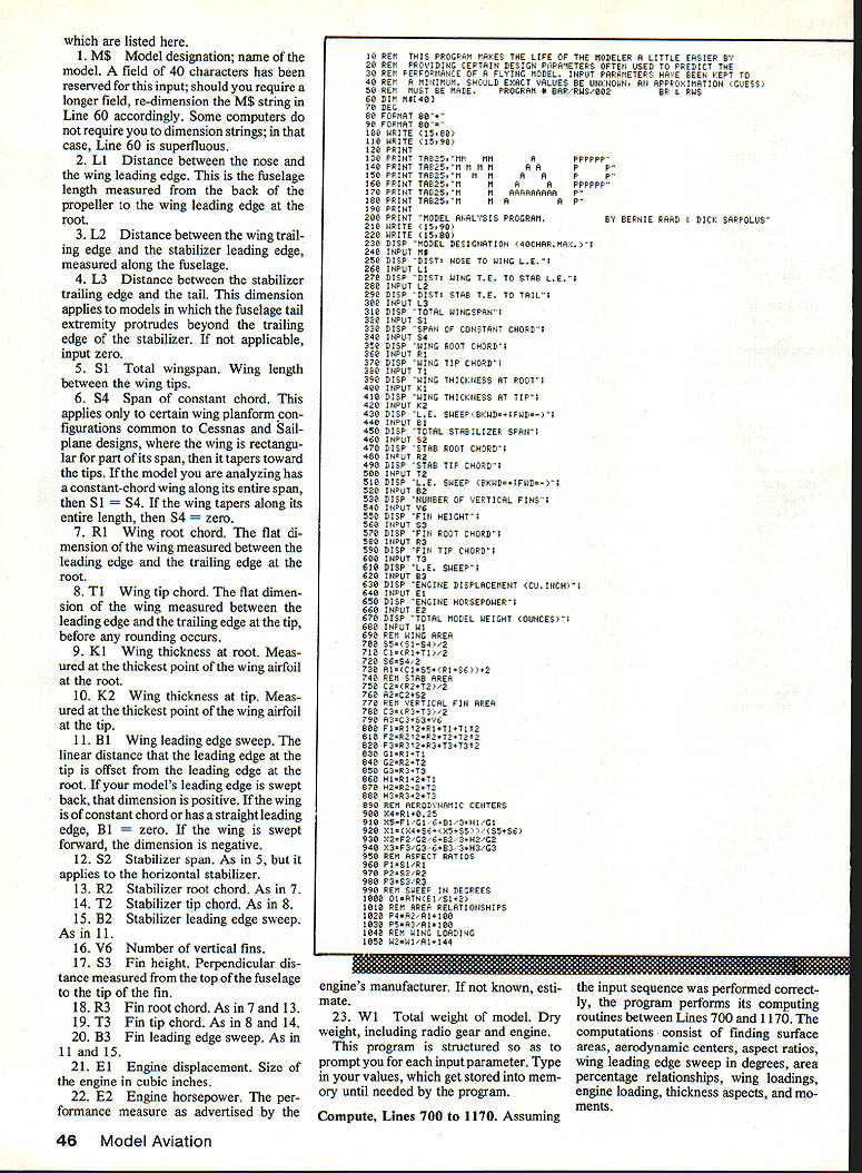
Input, Lines 230 to 690
Assuming that the listing included with this article is properly transcribed into your machine, the next step is to test it, i.e., run the program. In order to perform this task, you must furnish the 23 pieces of input information which are listed here.
- MS — Model designation; name of the model. A field of 40 characters has been reserved for this input; should you require a longer field, re-dimension the MS string in Line 60 accordingly. Some computers do not require you to dimension strings; in that case, Line 60 is superfluous.
- L1 — Distance between the nose and the wing leading edge. This is the fuselage length measured from the back of the propeller to the wing leading edge at the root.
- L2 — Distance between the wing trailing edge and the stabilizer leading edge, measured along the fuselage.
- L3 — Distance between the stabilizer trailing edge and the tail. This dimension applies to models in which the fuselage tail extremity protrudes beyond the trailing edge of the stabilizer. If not applicable, input zero.
- S1 — Total wingspan. Wing length between the wing tips.
- S4 — Span of constant chord. This applies only to certain wing planform configurations common to Cessnas and sailplane designs, where the wing is rectangular for part of its span, then it tapers toward the tips. If the model you are analyzing has a constant-chord wing along its entire span, then S1 = S4. If the wing tapers along its entire length, then S4 = zero.
- R1 — Wing root chord. The flat dimension of the wing measured between the leading edge and the trailing edge at the root.
- T1 — Wing tip chord. The flat dimension of the wing measured between the leading edge and the trailing edge at the tip, before any rounding occurs.
- K1 — Wing thickness at root. Measured at the thickest point of the wing airfoil at the root.
- K2 — Wing thickness at tip. Measured at the thickest point of the wing airfoil at the tip.
- B1 — Wing leading edge sweep. The linear distance that the leading edge at the tip is offset from the leading edge at the root. If your model's leading edge is swept back, that dimension is positive. If the wing is of constant chord or has a straight leading edge, B1 = zero. If the wing is swept forward, the dimension is negative.
- S2 — Stabilizer span. As in 5, but it applies to the horizontal stabilizer.
- R2 — Stabilizer root chord. As in 7.
- T2 — Stabilizer tip chord. As in 8.
- B2 — Stabilizer leading edge sweep. As in 11.
- V6 — Number of vertical fins.
- S3 — Fin height. Perpendicular distance measured from the top of the fuselage to the tip of the fin.
- R3 — Fin root chord. As in 7 and 13.
- T3 — Fin tip chord. As in 8 and 14.
- B3 — Fin leading edge sweep. As in 11 and 15.
- E1 — Engine displacement. Size of the engine in cubic inches.
- E2 — Engine horsepower. The performance measure as advertised by the engine's manufacturer. If not known, estimate.
- W1 — Total weight of model. Dry weight, including radio gear and engine.
This program is structured so as to prompt you for each input parameter. Type in your values, which get stored into memory until needed by the program.
Compute, Lines 700 to 1170
Assuming the input sequence was performed correctly, the program performs its computing routines between Lines 700 and 1170. The computations consist of finding surface areas, aerodynamic centers, aspect ratios, wing leading edge sweep in degrees, area percentage relationships, wing loadings, engine loading, thickness aspects, and moments.
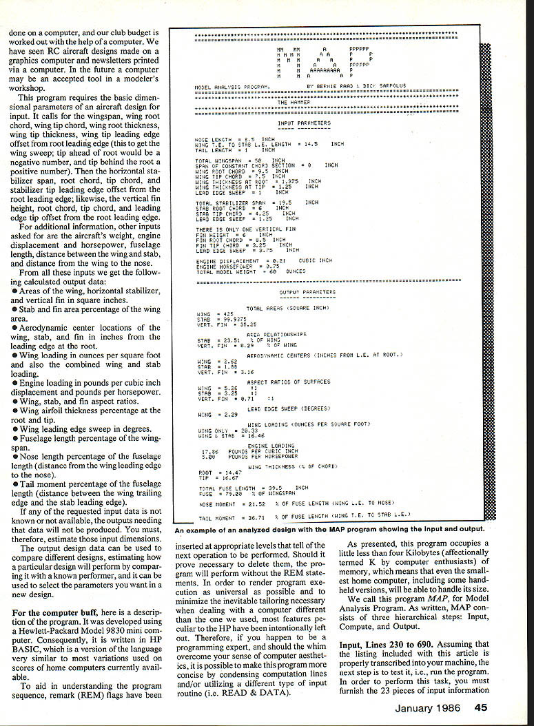
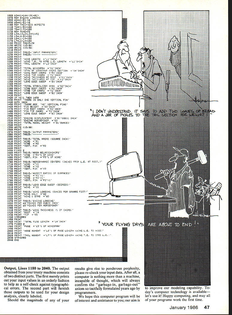
Output, Lines 1180 to 2040
The output obtained from your trusty machine consists of two distinct parts. The first merely prints out your input values in an orderly fashion to help as a self-check against typographical errors. The second part will furnish those outputs to be used for your design analysis, clearly labeled.
Should the magnitude of any of your results give rise to ponderous perplexity, please re-check your input data. After all, a computer is nothing more than a machine, incapable of thought, which will always confirm the "garbage-in, garbage-out" axiom so tactfully formulated years ago by programmers.
We hope this computer program will be of interest and assistance to you; our aim is to improve our modeling capability. Today's computer technology is available—let's use it! Happy computing, and may all of your programs work the first time.
Transcribed from original scans by AI. Minor OCR errors may remain.

