

To Assist in RC Canard Aircraft Design
Dick Sarpolus and Bernie Raad
Presented here is a computer program in BASIC language—easy to use on most home computers—to help in the design of canard aircraft. The program is a simple one and will provide a useful tool for design work; it will also be a fun exercise if you're learning how to use a computer at the same time. The hobby use of computers is growing rapidly, and the cost of home computers seems to be coming down just as rapidly. Judging by our local RC club, modelers are getting computers and they are readily available now to the extent that programs like this one can be practical and useful.
We have seen in club newsletters and heard in discussions that many modelers are already using computers in our hobby, probably predominately in RC soaring—for airfoil analysis, performance prediction, wind-tunnel data interpretation, etc. We expect to see more computer programs presented in the model magazines in the future; we're at an early stage and starting off in an exciting direction. The use of computers and various programs can only help in the advancement of RC aeromodeling.
We became involved in this effort during the design of the Firebolt canard RC model featured in this issue. The "mystery" in designing a canard is determining the location of the balance point and the size of the vertical fin area. Many modelers design by the trial-and-error procedure, basing a new design on a known successful past aircraft and changing some dimensions to see what happens. This can be done successfully, but with a canard there are few existing aircraft to use for reference.
Aerodynamic formulas are available to assist us, and you don't have to be an aerodynamic engineer to use them. Ron Van Putte, who writes MA's Sport and Aerobatics column, included several basic formulas necessary for canard design in his June 1980 column. Those formulas provide the center of mass (or balance point) location for any canard design and also indicate if the vertical fin area of a design is sufficient. Of course, a computer program is not necessary for the use of those formulas, but our program makes it easier and faster to get the answers and provides a few additional outputs for your use.
The big advantage of having a computer do the calculations is the ease of performing them on a number of design variations as you work to finalize a new airplane. For example, as the wing is swept back further, the balance point must move back. As the horizontal stabilizer is moved forward away from the wing, the balance point must move forward. If the stabilizer area is decreased, the balance point will move to the rear. Many other variations can be considered. In working up a new design, many variations can be run through the calculations until you settle on the final airframe configuration that is desired.
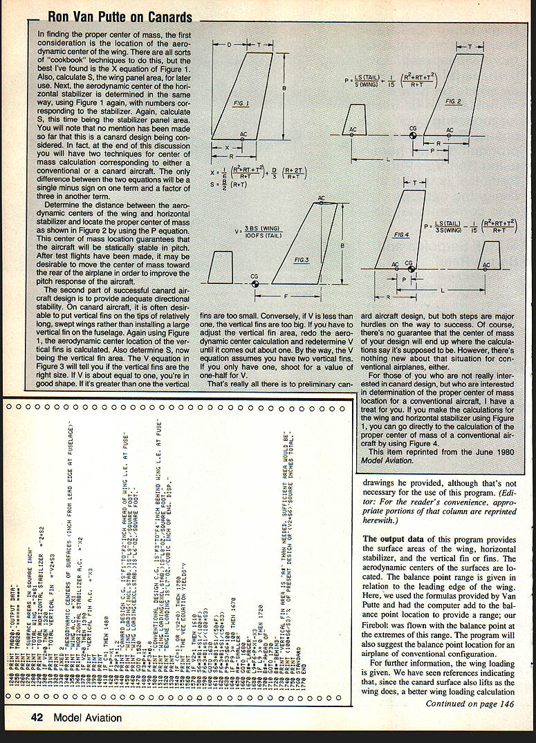
We recommend that you look at Van Putte's June 1980 column for a complete explanation of the formulas along with the drawings he provided, although that is not necessary for the use of this program. (Editor: For the readers' convenience, appropriate portions of that column are reprinted herewith.)
The output data of this program provides the surface areas of the wing, horizontal stabilizer, and the vertical fin or fins. The aerodynamic centers of the surfaces are located. The balance point range is given in relation to the leading edge of the wing. Here, we used the formulas provided by Van Putte and had the computer add to the balance point location to provide a range; our Firebolt was flown with the balance point at the extremes of this range. The program will also suggest the balance point location for an airplane of conventional configuration.
For further information, the wing loading is given. We have seen references indicating that, since the canard surface also lifts as the wing does, a better wing loading calculation should include the canard area as well. This program gives both answers. The engine loading, in pounds per cubic inch of engine displacement, was added to the program for interest; it shows the sort of calculations a computer can do so easily. The vertical fin area is analyzed according to the formula, and the program advises if more area is needed or if the design contains excess area. The Firebolt design has excessive fin area and flies well.
In summation, this is the story behind a computer program usable to assist in the design of canard RC aircraft, and we hope it is of interest and help to you. Happy computing!
Explanation and description of the program
This program was developed using a Hewlett-Packard Model 9830 mini-computer and consequently is written in HP BASIC. This version of BASIC is very similar to most variations of the language now used for innumerable home computers.
The program consists of Display, Input, Computation, and Print commands. For the display routines the screen is cleared and then a brief title and copyright notice appears. All input data for the particular plane being analyzed is typed in and checked for invalid entries. A few constants such as conversion factors (inches to feet, etc.) are built into the program.
The computed data is printed in a neat, easy-to-read format. For convenience the program has a subroutine to convert inches to feet and inches for printing. We have found this helpful when laying out plans and when checking shop measurements.
Because many different BASIC dialects are in use by hobbyists, we tried to keep the program structure and commands simple. You may have to alter some input/output statements when adapting the program to your own computer. For those of you who own or use machines which cannot handle lines of 80 characters, special care was taken to keep computation lines shorter than 32 characters. Input and output statements can be shortened by splitting them into two or more lines and should present no problem even to a budding programmer.
As presented, this program occupies a little less than five kilobytes of memory, which means that it can be handled by computers with as little as 8K of RAM. Most special features peculiar to the HP were left out in order to make the program more universal.
With the introduction over, we'll get down to business.
Input (lines 90 to 530)
In order to run this program and get the results, you will need 19 pieces of information, explained as follows:
- (C5) Model designation. A 30-character field has been provided to identify the design being analyzed. This field includes letters and numerals, symbols, or a combination of all three. Should you need a larger field, be sure to add sufficient C$ in line 10.
- (B4) Total wingspan, in inches.
- (R1) Wing root chord, in inches. Distance between leading edge and trailing edge, measured at the wing center.
- (T1) Wing tip chord, in inches.
- (D1) Leading edge sweep, in inches. Distance of tip relative to root and resulting from leading edge sweep. If the leading edge is perpendicular to the fuselage, that value is zero (no sweep). If the leading edge is swept back, the value is positive. If the leading edge is swept forward, the value is negative.
- (B5) Total span of the horizontal stabilizer, in inches.
- (R2) Stabilizer root chord, similar to item 3.
- (T2) Stabilizer tip chord, similar to item 4.
- (D2) Stabilizer leading edge sweep, similar to item 5.
- (V2) Number of vertical fins. The vertical fins and their positioning have no effect on the balance point location. This input is useful only for canard designs for which stability is affected by fin characteristics. Therefore, if dealing with a conventional design (wing ahead of stab) assign zero to this value, and the program will skip inputs 11 to 15.
- (B3) Vertical fin height, in inches.
- (R3) Fin root chord, similar to items 3 and 7.
- (T3) Fin tip chord, similar to items 4 and 8.
- (D3) Fin leading edge sweep, similar to items 5 and 9.
- (L3) Fin offset from wing leading edge, in inches. This dimension locates the leading edge of the vertical fin with respect to the wing leading edge at the root.
- (C) Enter 2 for canard, 1 for conventional.
- (L1) Distance between stabilizer and wing root, in inches. This is the length of fuselage between the wing and stabilizer.
- (W1) Total weight, in ounces.
- (E9) Engine size, in cubic inches.
The structure of the program is such as to prompt you for the value of each of the parameters listed above. All you then have to do is enter the particular value, which gets stored in memory until it is used subsequently.
Compute (lines 540 to 850)
Assuming that the input sequence was performed correctly, the program then performs most of the computations needed between lines 540 and 850. These computations involve finding aerodynamic centers of the surfaces, surface areas, arm moments, balance point or center of gravity location, wing loading, and engine loading.
Output (lines 860 to 1760)
Lines 860 to 1760 mostly comprise a PRINT routine. The output is subdivided into three parts.
- Part I — Identifies the program and its function.
- Part II — Prints out most input parameters. This allows you to double-check your input data.
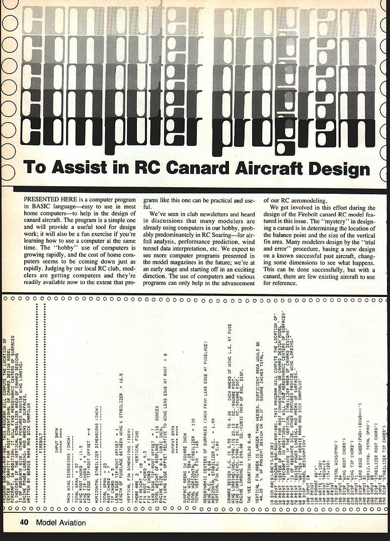
- Part III — Prints out the findings of the program in a neat format. This part is labeled Output Data and can be seen in the sample printout included with this article.
Transcribed from original scans by AI. Minor OCR errors may remain.

