
Conscientious Objector
Bill Baker
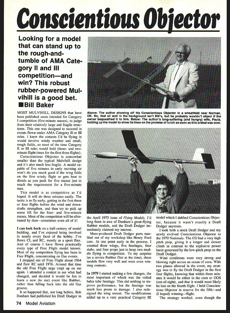
Looking for a model that can stand up to the rough-and-tumble of AMA Category II and III competition—and win? This robust rubber-powered Mulvihill is a good bet.
Most Mulvihill designs that have been published seem intended for Category I competition (five-minute maxes), judging from their relatively large and fragile structures. This one was designed to succeed in events flown under AMA Category II or III rules. I knew the contests I'd be flying in would involve windy weather and small, rough fields, so most of the time Category II or III rules would hold (three- and two-minute flight times for the first three flights).
Conscientious Objector is somewhat smaller than the typical Mulvihill design and it's also much less fragile. A model capable of five minutes in early-morning air won't do you much good if the wing folds on the first windy flight or gets beat to shreds as you push for five maxes just to reach the requirement for a five-minute max.
This model is as competitive as I'd hoped. It will do three minutes easily. The tactic is to fly early, getting in the first three or four flights before the wind and downdrafts strengthen, and then try to pick up some lift for the four- and five-minute maxes. Most of the competition will be eliminated by then—sometimes even all of it!
I can look back on a half-century of model building and have enjoyed being involved in nearly every facet of the hobby. I've flown CL and RC, mostly as a sport flier, and of course I have flown practically every type of Free Flight model known. Most of my competition flying has been in Free Flight, concentrating on gas events. I dropped out of Free Flight about 1964 and flew RC until 1976. Around that time the old Free Flight urge crept up on me again. I attended a contest to see what had changed, and decided it would be fun to learn a new (to me) event like Rubber, rather than falling back into the old Gas groove.
It so happened that, not long before, Bob Dunham had published his Draft Dodger in the April 1975 issue of Flying Models. I'd long been in awe of Dunham's great-flying Rubber models, and the Draft Dodger immediately claimed my interest. Mass-produced Draft Dodger parts tumbled out of my workshop like Henry Ford cars. At one point early in the process, I counted three wings, five fuselages, four stabs, and four props just to keep two models flying in competition. To my surprise (as a novice Rubber flier at the time), these models flew very well and were winning contests.
In 1979 I started making a few changes, the most important of which was the rolled-balsa-tube fuselage. This did nothing to improve performance, but the fuselage was much less prone to damage. I also redesigned the wing mount. The modifications added up to a very practical Category III model which I dubbed Conscientious Objector, because it wasn't exactly a Draft Dodger anymore.
I took both a stock Draft Dodger and my newly evolved Conscientious Objector to the 1979 Nationals. The CO had a very high-pitch prop, giving it a longer and slower climb in contrast to the explosive power burst generated by the low-pitch prop on the Draft Dodger. Wind conditions were very strong and blowing right across an ocean of corn. With two planes allowed in the event, my strategy was to fly the Draft Dodger in the first four flights, knowing that within three minutes it would be either in the corn or OOS (out-of-sight), and that it would most likely be lost on the fourth flight. I held Conscientious Objector in reserve for the fifth—and (I hoped) winning—flight.
The strategy worked, even though the Draft Dodger was damaged after each flight (mostly wing mount damage and diagonals broken out). With its explosive climb rate the model flew through ground turbulence that the slower-climbing Conscientious Objector wouldn't have been able to cope with.
Still using the tubular fuselage, I continued to adapt the Conscientious Objector until virtually no remaining parts were identical to those of the Draft Dodger. I adapted a prop published years ago by Frank Parmenter, borrowed the stabilizer structure from Bob White's Twin Fin, used his simple Z-bar-type propeller hub, copied the wing mount and a few other ideas from Jim O'Reilly, invented a better winding hook, and worked out a simple and reliable dethermalizer setup that probably owes something to many different people. I tried longer motor tubes, a variety of wings (some with more area or different dihedral schemes, others with different airfoils), and I experimented with several propellers.
The model presented here represents what, in my judgment, is the best compromise for achieving my key objective: a Mulvihill that's competitive in Category III. You might want to increase the wing area to 300 sq. in. and the motor tube to 42 in. so that the model will serve for your flyoff (five-minute) rounds, or for Category I. You may also want to increase the propeller diameter a half-inch or so. For 95% of the Mulvihill flying done in the U.S., the model as presented is very competitive.
After my 1979 AMA Nationals win with the Draft Dodger, I flew in two more Nationals under Category III rules and placed in both (third and fifth). The only time the Conscientious Objector failed to place at the Nats was when the event (to my surprise) was flown under Category I rules. As time went on my interests shifted to Old-Timer events, and I began attending the SAM Champs instead of the AMA Nats. Nevertheless I continued to do well with my Conscientious Objector at local and regional contests until I found myself unable to meet the physical demands of Free Flight competition. At present I'm enjoying RC sailplanes. But the Conscientious Objector has a permanent niche in my affections, and I'd like to think that somewhere, someone will be flying this Category III Mulvihill—and winning.
Construction
Motor tube (fuselage)
The motor tube houses the motor and holds the other parts of the airplane in proper relationship to one another. Though several fuselages were built square in cross section, the tube configuration has the best strength-to-weight ratio.
- Use 1/4 x 4-in.-wide, 6- to 8-lb. A-grain balsa. Make sure the wood is uniform in density and grain through the entire length of the piece. If it's much harder on one edge, or if it transitions to C-grain, don't use it.
- Using a metal straightedge, trim the sides true. Seal the wood on one side only with two coats of Deft (semigloss) or clear dope. Sand gently between coats.
- When dry, wet the entire piece with water. This will cause it to curl as the unpainted side expands. Form the wet balsa around a 1-1/4-in.-dia. dowel, after first scoring a line down the center of the dowel to align the balsa.
- Wrap the wood gently with strips of cloth, gauze, or an Ace bandage, and let it dry. Remove the wood from the dowel, apply a thin coat of glue to the edges, and draw them together. Secure with bits of masking tape, and allow to dry.
Make a one-inch-wide nose doubler and a tail doubler about 1-1/2 in. wide from similarly prepared balsa. These doublers will reinforce and protect the soft balsa ends where the nose plug, tail cone, and mounting fittings attach.
I tapered the end of my forming dowel with a plane and rasp to more easily form the tail cone. The amount of taper isn't critical: from 1-1/4 in. narrowing to 3/4 in. is about right.
Make a circular former from hard 1/8-in. balsa (or two cross-grained 1/8-in. pieces). Fit this former inside the aft doubler at the end of the motor tube to prevent damage to the tapered cone should the motor break. Place another 1/8-in. former in the area of the SHOC (Sky Hoppers of Orange County) stabilizer mount.
Don't worry if your rolled tube isn't perfectly circular. Lay it on a table and allow it to roll until it stops. Let that flat spot be on one side, with the top and bottom 90° to it. If there is a discernible curvature from side to side, let the concave side be the bottom. When joining the tail cone, eyeball it as closely as you can. If it isn't a perfect cone, mount it so that the top forms the straightest line to the motor tube.
The motor pin must be strong, since tremendous force is exerted upon it. The pin must, of course, be removable in order to change motors. Use at least a 1/4-in. pin, and reinforce the tube where the holes are made for it.
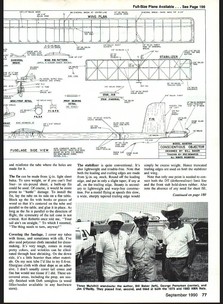
Fin and tail
The fin can be made from 1/16-in. light sheet balsa. To save weight, or if you can't find four- to six-pound sheet, a built-up fin could be used, though it would be more prone to battle damage.
To install the fin:
- Lay the tube on its side on a flat table.
- Block up the fin with books or pieces of wood so that it is centered on the tube and parallel to the table, then glue it in place.
As long as the fin is parallel to the direction of flight, the symmetry of the tail cone is not critical.
Covering
I cover my tubes with tissue, and sometimes with silk. I've also used polyester cloth intended for dressmaking—it’s very tough, comes in many colors, and wrinkles can be eliminated through heat shrinking, though it's a bit heavier. On future tubes I would like to try 0.6-oz. fiberglass cloth with clear dope as an adhesive.
I don't usually cover tail cones and fins, but would use tissue if I did. These uncovered areas, including the prop, are usually finished with Teflon sealer/gloss (a wood filler/sealer available in any hardware store).
Stabilizer
The stabilizer is conventional, lightweight, and trouble-free.
- Both leading and trailing edges are made from 1/8-in.-sq. stock. Round off the leading edge and put in only a slight taper, if any, on the trailing edge. Beauty is secondary to lightweight and warp-free construction.
- For slow-flying models, a wide, sharply tapered trailing edge is excess weight—hence truncated trailing edges are used on both the stabilizer and wing.
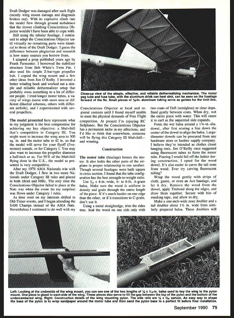
- Note that only one point is needed to connect both the DT (dethermalizer) limit line and the front strobe hold-down rubber. The stab is so lightweight that it aligns itself with the small notch for the DT line in the trailing edge. The action of the shock-type stab from the notch centers the leading edge well enough, negating any need for keying. An added advantage of this system is that it's free to move when meeting an obstruction and will not be damaged.
The notched peg that holds the rubber and DT line can be made from 1/16-in. ply, a popsicle stick or tongue blade, or even from a wood dowel or aluminum tubing. The peg mounting platform in the stabilizer should be 1/16-in. ply, as the peg must be able to withstand a certain amount of strain.
Wing
With the heavy-duty spar shown on the plans, I've never broken a wing. Maybe the spar is too heavy, but I like it.
- The upper main spar can be made either from very hard balsa or from spruce. Other spars can be medium (8–10-lb.) balsa.
- The shear webbing between the spars is very important. Installing the pieces along the centers of the spars is ideal, but making them full depth and locating them along one side is easier and more than adequate.
- The 1/8-in. hard balsa angled center dihedral brace can also be made full depth.
Shim up the ribs 1/32 in. above the leading edge so that a small taper can be made. This will shape the leading edge to conform to the undercambered ribs. Shim up the rear end of the ribs and the trailing edge 1/32 in. for the same reason.
The wing can be built without a jig, but if you're going to build several wings, a jig is highly recommended. The jig I used allowed the wing to be built in one piece, except for the lower spar which was added later. My use of jigs dates from the discovery that many of the warps that plagued me were induced during the process of adding the dihedral.
I don't usually shim in any washout, since about 1/2 in. of washout seems to occur automatically when the tissue is doped.
The wing mount on the motor tube is designed as a lightweight, rigid platform for the wing to rest on. A quick way to achieve a perfect fit is to wrap a piece of sandpaper around the tube and lightly sand the mount base to shape. Don't glue the wing mount to the fuselage until the model is ready to fly, as it must be adjusted to achieve the correct CG. After the mount is glued in place, make sure there's enough stabilizer tilt to produce a left turn.
Propeller
I may try to write a detailed article on propeller carving soon, but the subject has been covered thoroughly elsewhere. Wood selection is of primary importance—the block should be hard (about 14 lb.) and of uniform density to produce blades that are both thin and strong.
Steps and tips:
- Lay out the top and bottom profiles, making sure the centerline of the top profile is parallel to the edge of the block. Do the same for the bottom line of the side profile.
- Set the block in a drill press and drill the hole for the hinge. Cut out the profiles on a bandsaw.
- Carve the bottom of the blades first, completely finishing them before starting on the top. Keep track of right and left blades.
- Try for about 1/16 in. of undercamber at the midblade, progressing to no undercamber at the tip.
- Begin carving the top of the blade by getting it down to about 1/4 in. thickness. Make the high point of the airfoil about one-third of the chord. Carve thin slices, not chunks. The thickest part of the blade should be about 1/16 in. at the tip and 1/8 in. at midblade.
- Add 1/64- or 1/32-in. ply doublers and the 3/32-in. O.D. tubing for the hinge.
- Place the blade on a Z-bar hub and drill the holes for the hinge pins with a 1/16-in. drill mounted in a pin vise. Take extreme care so the blades track properly in alignment.
- Finish the propeller with dope (available through model catalogs if not at your local hardware).
Nose plug, bearings, and hub
The nose plug is made from 1/4-in. sheet balsa laminated cross-grained. The first laminate fits inside the motor tube, and the second forms the face and should conform to the outside shape of the tube.
- A brass or aluminum tube can be inserted in the plug, with smaller pieces of tubing (~1/8-in. long) at each end to form bearings for the wire prop shaft. Use Loc-Tite or similar to adhere the inner tubes to the outer tube. Use CYA (cyanoacrylate) glue to install the completed bearing in the nose block.
- Add a plywood face at least as large as the external ball bearing so that it won't crush the balsa.
- Use a good spring (such as those available through FAI Model Supply). Don't use a ball-point pen spring or other cheap alternatives that might take a set.
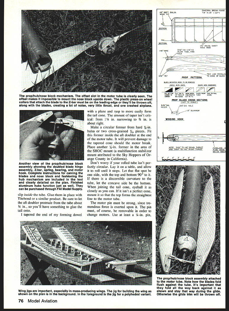
Make the Z-bar out of 1/16-in. music wire. Use Sta-Brite or an equivalent hard solder—never trust soft solder to hold a propeller hub together. First balance the Z-bar alone, then attach the blades and balance again. Blade batches averaged eight to ten grams; pair-match blades to similar weights if you make many.
Winding hook and motor
The winding hook shown on the plan works well. The rubber will stay centered if the hook is made and positioned correctly. If you don't understand winding hooks, winding tubes, stooges, and other aspects of rubber-powered model technology, buy Don Ross' Rubber Powered Model Airplanes from the AMA Supply and Service catalog.
The motor is made up of enough 3/8-in. strands to weigh 85 to 90 grams dry. Consistency is what's wanted; there should be no slack. I used this size motor on my Mulvihill designs and on nearly all of my Old-Timer Rubber models. Choose one motor and get used to it—consistency reduces stress and mistakes at contest time.
Trimming and balancing
- The center-of-gravity shown on the plan is best for all-around thermal and windy-weather flying. For early-morning still air, the CG could be moved slightly aft and the decalage reduced.
- Set the SHOC stabilizer mount about 1/8 in. into the tail cone by making careful cuts with an X-Acto saw and removing the wood between the cuts to create a flat spot to support the mount. It should sit slightly to the right, making the left tip about 1/8 in. higher than the right.
- The wing mount should have no incidence relative to the motor tube. The decalage is established by the angle of the stabilizer sitting on the aft block under its trailing edge. This angle should be two or three degrees (about 1/8 in. higher at the trailing edge).
- Glue the wing mount in place with the motor loaded, making sure the balancing mark is over the CG. Use a large table as a square, set the wing on the mount square to the motor tube, and key it by gluing 1/16 x 1/8-in. balsa strips to the bottom of the wing across the chord. The wing will then go in the same position each time and won't shift during flight.
- Key the nose block assembly to the fuselage. A bit of 1/8-in. ply is needed for the wood screw stop—don't omit it or the screw will tear out of the balsa.
- With the stop tight against the screw and the nose plug in place, position the prop blades folded on either side of the motor tube and determine the best placement of the 1/8 x 1/4-in. spruce key that locks the nose block against rotation. Cut the inner nose block ring for the key, then slot the motor tube to match. It's important to have two key points to distribute the shock of the shaft striking the screw. Double the motor-tube covering material around the key slots.
- The small hooks on the prop blades are made of soft wire (paper-clip wire). Note their location somewhat aft of the hinge line when the blades are folded. A rubber band from one hook goes over the front of the Z-bar and back to the other hook. Change the rubber bands before every contest for two reasons: ensure the blades fold all the way back against the motor tube and avoid deterioration in the sun.
- With a drafting triangle and the worktable as a square, check the propeller blades for track and identical angle in each blade. Also check the static balance.
- Cut a small rudder tab, about 3/4 x 1/2 in., from the trailing edge of the fin and glue it back in place with approximately 3/16 in. of left deflection.
- Check the motor tube for downthrust and right-thrust angles, which should each be about 3/16 in.
- The model should weigh about eight ounces ready to fly, with 90 g (about three ounces) contributed by the motor.
- Oil the propeller bearings, lube the motor, and you're ready to fly.
Flight testing and trim adjustment
- Fly the model into light lift first to check climbing characteristics.
- If the climb is too nose-heavy, move the motor tube forward slightly or reduce propeller pitch.
- If the model tends to spiral or turn tightly, add a bit of right thrust or increase right rudder.
- If the model dives on the glide, add some decalage or move the CG slightly forward.
- If it balloons and stalls in the glide, move the CG slightly aft.
- Small trim tabs and minute changes to downthrust and right thrust will usually cure most problems.
- Once the model trims out for a good climb and a gentle glide, try it in the type of conditions you plan to fly in competition.
- High-pitch props give a longer, slower climb; low-pitch props provide an explosive, fast climb.
- The model should climb in a right turn and glide to the left. Glide is controlled by stabilizer tilt and the thickness of the aft incidence block; climb is adjusted only after satisfactory glide trim has been established.
- Adjust thrust line by gently filing the end of the motor tube to change the angle at which the nose block rests—do this in very small increments. Don't fly at full power until you're completely satisfied with the model's trim.
- When ready to fly at full power, launch the model at about a 45° angle; it tends to go where it's pointed. If a model won't turn left in glide without excessive stabilizer trim, letting it turn right in glide as well as climb can be a practical option, but left glide and right climb is the safe convention.
Dethermalizer
The guide tube under the SHOC stabilizer mount has multiple functions: it conducts the DT line, keeps the stabilizer rubbers from touching the line, and serves as the DT limit stop.
- A piece of monofilament line can be used as a DT line. A loop at one end is fitted over the peg on top of the stabilizer. The rubber must be installed over this loop to stay in place. The rubber loops over the peg, extends across the leading edge of the stabilizer, then goes down and around the fuselage and back up to the peg.
- A bit of fuel tubing serves nicely as a DT line limit. It can be tied to the line with a simple overhand knot and adjusted to strike the line guide tube under the SHOC mount. The tubing should be adjusted to allow about a 45° stabilizer DT angle.
- Tied on to the other end of the DT line is a paper-clip wire hook. The fuse rubber band extends from the hook, across the fuselage, and around the motor peg.
- Use a sharpened piece of aluminum tubing to drill holes in the fuselage; this makes a cleaner hole than a drill. Use a 1/8-in. tube for the fuse holder, extending it through both sides of the fuselage. That way you can poke fuse material through with a piece of wire and pull out more fuse if needed. Glue the tube firmly in place.
- The heat sink can be made from an aluminum can, but it must be selected with care.
I will gladly try to answer any questions you might have about the Conscientious Objector. Send a SASE to me at 1902 Peter Pan St., Norman, OK 73072.
Transcribed from original scans by AI. Minor OCR errors may remain.

