
Control Cable Systems
Why not give your World War I classic model the finishing touch and install a scale-like working cable control system? Here's a complete description of how to do it. Frank P. Stanton
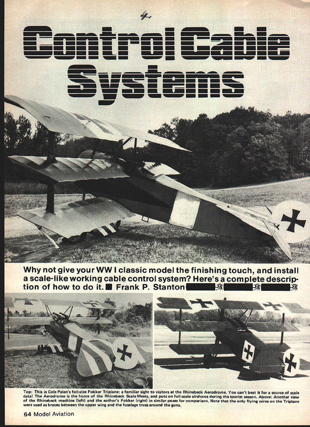
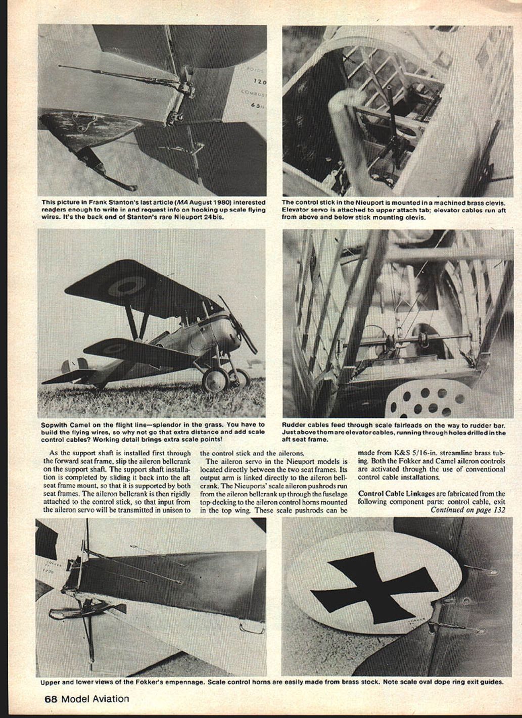
There has always been a continuing, enthusiastic interest in flying models of the Great War era. That interest centers on the fascinating airplanes themselves and includes a yen for information on specific operational features often missing in general construction articles. Consider adding a unique scale touch to your next historic vintage model by installing a fully functional control cable system to actuate the flight control surfaces. Such a system adds a practical, realistic aspect to a model of the chivalrous period at the dawn of aeronautical history.
Full-scale Great War planes used control cable linkages to provide aileron, elevator, and rudder control. To duplicate these functionally in miniature, three distinct sub-assemblies are required:
- Control-stick sub-assembly
- Control cable linkages
- Rudder-bar sub-assembly
The details illustrated here can fit any World War I model with full running rigging. Choose either of three popular types — the nimble Nieuport 17 or 24bis series, the feared Fokker Dr.I triplane, or the classic Sopwith Camel.
Control Stick Sub-assembly
The pilot's control stick serves as the actual attachment point for the elevator and aileron controls. It consists of the following major component parts:
- Aileron bellcrank
- Brass clevis
- Wheel collar
- Steel pivot pin
- Support shaft
- Control-stick cable attach tabs
- Pushrod
Construction and assembly:
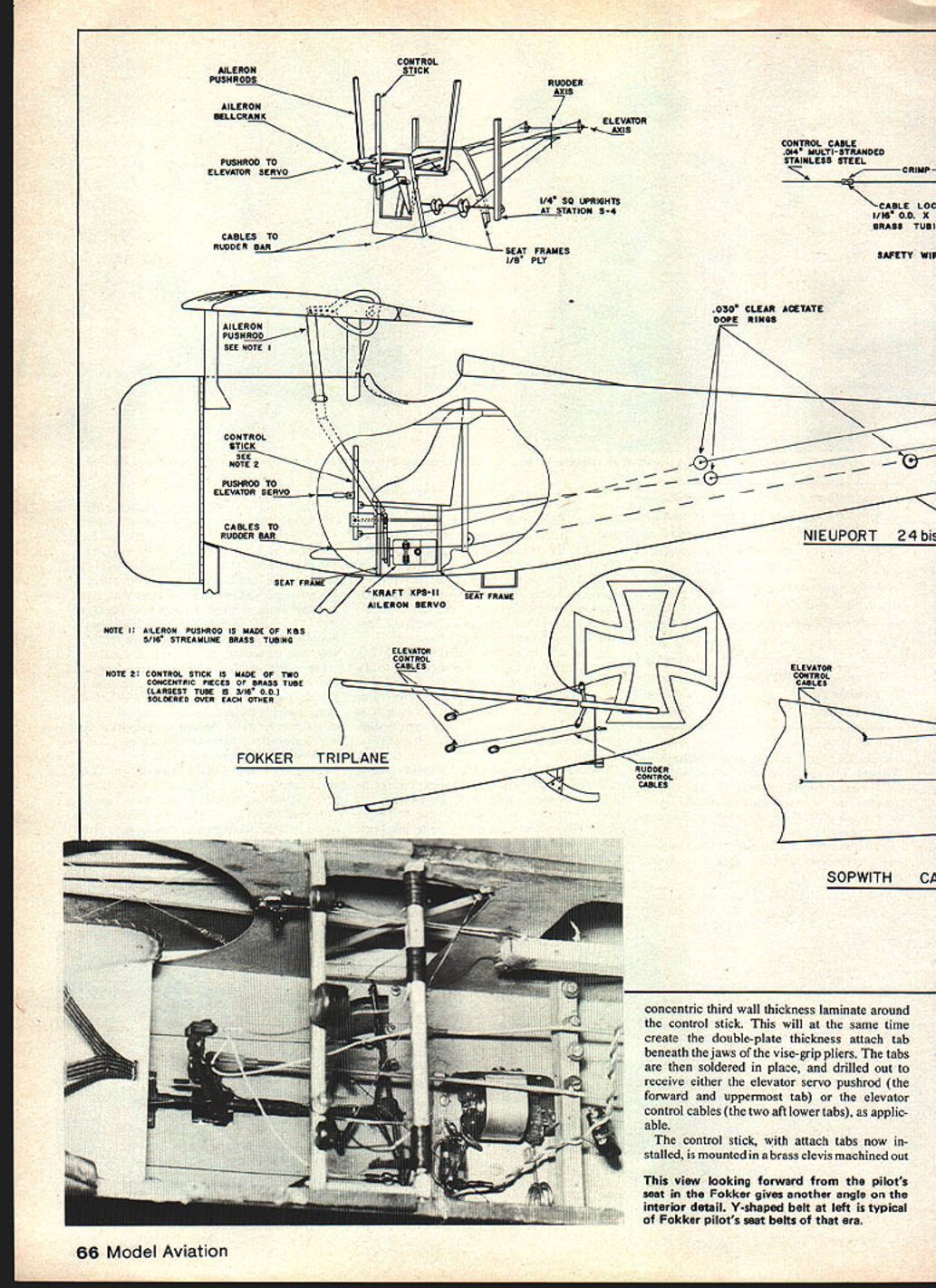
- The control stick is made from concentric brass tube sections. The largest tube (3/16-in. O.D.) is soldered over a smaller tube to form the basic stick. A concentric third wall-thickness laminate around the control stick creates a double-plate thickness to which the attach tab beneath the jaws may be fastened.
- Tabs are soldered in place and drilled to receive either the elevator servo pushrod (forward, uppermost tab) or the elevator control cables (two aft, lower tabs).
- Three attach tabs are mounted on the control stick. All three are made from 1/16-in. O.D. brass tubing cut to the eventual width of the tab. Slide each piece of 1/16-in. tube into location on the stick, squeeze in place with vise-grip pliers so the tube reforms as a clamp, then solder. Avoid solder flow into the inside of the tube. After soldering, ream or drill out the tube bore.
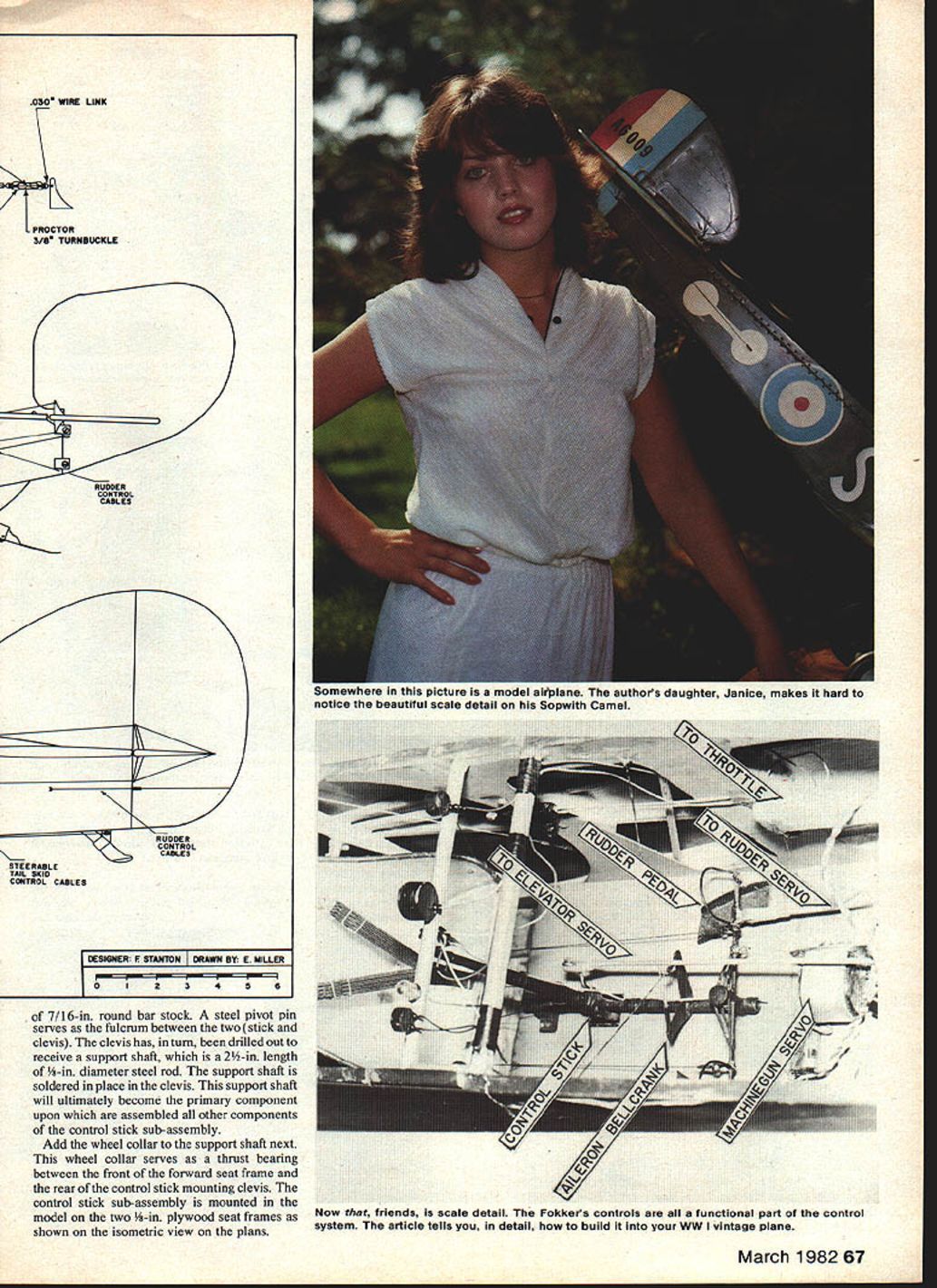
- A 7/16-in. round bar-stock steel pivot pin serves as the fulcrum between the two stick clevises. The clevis is drilled to receive the support shaft, which is a length of steel rod (typically about 2-1/2 in. long and 3/16-in. diameter, depending on model). The support shaft is soldered in place in the clevis. This support shaft becomes the primary component upon which all other parts of the control stick sub-assembly are assembled.
- Add the wheel collar to the support shaft next. The wheel collar serves as a thrust bearing between the front of the forward seat frame and the rear of the control stick mounting clevis.
- As the support shaft is installed first through the forward seat frame, slip the aileron bellcrank onto the support shaft. Slide the support shaft back into the aft seat frame mount so it is supported by both seat frames. Rigidly attach the aileron bellcrank to the control stick so that input from the aileron servo is transmitted in unison to the control stick and the ailerons.
- In the Nieuport models, the aileron servo is located directly between the two seat frames and links directly to the aileron bellcrank. Nieuport scale aileron pushrods run from the bellcrank up through the fuselage top-decking to the aileron control horns mounted in the top wing and can be made from K&S 5/16-in. streamline brass tubing. The Fokker and Camel aileron controls are typically activated through conventional control cable installations.
Aerodynamic loads from flight controls can be very strong during acrobatic maneuvers; build the stick assembly stoutly and never underestimate these forces.
Control Cable Linkages
Control cable linkages are fabricated from the following component parts:
- Control cable
- Exit guide
- Wire link
- Cable lock
- Turnbuckle
- Safety wire
Construction and installation:
- Use .014-in. multi-stranded stainless steel cable for control cables. Cut appropriate lengths to make a double run from the control horns through the applicable control stick attach tab for aileron and elevator controls. Each rudder cable makes a single run from control horn to rudder bar. Include sufficient excess for installation and final adjustments.
- Attach cables to turnbuckles at the control horn end after the cables are run through the airframe. Loop the cable through the forward eye of the turnbuckle, then double it back parallel to itself.
- Secure the doubled-up cable with cable locks made from short lengths (about 3/16-in.) of 1/16-in. O.D. brass tubing. Slip these over the doubled cable, crimp tightly, and solder in place to form the lock.
- Provide small guides where cables pass through the fuselage to prevent chafing and maintain the proper lead angle. Make guides from short pieces of brass tubing flared at both ends and soldered into the structure. Install fairleads wherever the cable changes direction sharply.
- Use turnbuckles to adjust cable tension. Install turnbuckles at the control horn end so adjustments can be made after the cables are run. Safety-wire the turnbuckles to prevent rotation and loss of adjustment. Light lubrication where the cable passes over pins or through guides will reduce wear.
- On Nieuports, Proctor 3/16-in. turnbuckles are appropriate. For the Fokker and Camel, Proctor turnbuckles are too large for scale realism. Fabricate scale turnbuckles from 3/16-in. lengths of 1/16-in. O.D. brass tubing: chamfer both ends to achieve a tapered silhouette and solder .030-in. wire loop eyes into each end for attachment.
- Drill through the center of each scratch-built turnbuckle with a #60 bit and run a safety wire through this hole and out through each eye of the turnbuckle. Twist the safety wire ends together along the turnbuckle body to lock the adjustment. This duplicates a scale feature and prevents inadvertent readjustment from vibration.
- Attach turnbuckles to the control horns using .030-in. wire links made in a Figure-8 shape. Each loop of the figure-8 has an open gap at the center so it can slip over the attachment splice and control horn. Bend the loops of the 8 so they are 90 degrees opposite each other: the loop that connects with the turnbuckle is in the vertical plane, while the loop that connects with the control horn is horizontal. Slip the wire link over the attachment eye and solder closed the gap on that loop; leave the loop over the control horn open, with cable tension keeping it locked in place. Leaving one loop open facilitates disassembly of removable horizontal tail assemblies (a feature of several vintage kits).
- For safe operation, all control cables should be snug but not drum-tight. Install all cables with sufficient slack for assembly and alignment, then tension and final-trim the system with the turnbuckles. Check for smooth operation and binding at guides or pulleys. After final adjustment, secure and dress all cable terminations, solder cable locks, and apply safety wire as required. Periodic inspection of fittings and cable tension will prevent failures later.
Notes on spacing and variations:
- Cable lock placement and spacing vary significantly between types; the Nieuport spacing is considerably wider compared to the Fokker and Camel.
- Cable locks are fed over the doubled-up cable, crimped tightly, and soldered to form a secure lock.
Exit Guides and Aircraft Variations
Scale locations for fuselage control cable exit guides are shown on plans for each aircraft and vary by type:
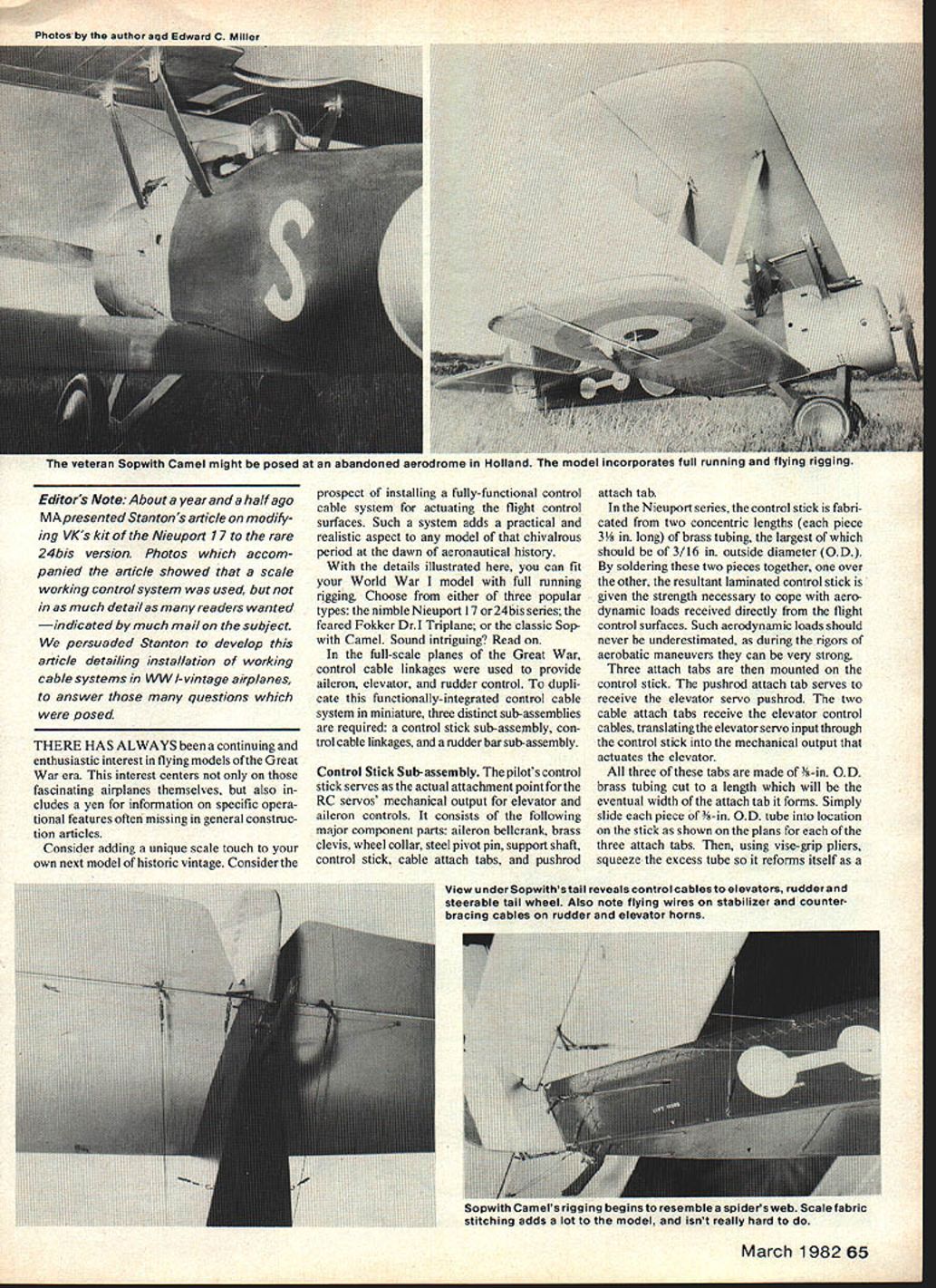
- Nieuport: employs circular "dope rings" laminated to the fabric covering on the fuselage. Dope rings can be made from .030-in. clear acetate sheet.
- Fokker: uses an open race-track design exit guide, also made from .030-in. clear acetate sheet.
- Sopwith Camel: uses tubing recessed in the fabric covering of the fuselage; simulate this with nylon plastic tubing.
Other Camel-specific features:
- The Camel includes a steerable tail skid. Control cables from the tail skid run to the rudder bar along with the rudder cables.
- The Camel also adds counterbracing cables that run from its control horns back through the trailing edge of the flight control surfaces.
The types and locations of control horns vary between aircraft; refer to the plans for specifics.
Rudder Bar Sub-assembly
- The rudder bar sub-assembly serves as a bellcrank that translates rudder servo input to the rudder control cable output. It can be built from brass tubing or plywood.
- Add scale accoutrements such as rudder pedals, stirrups, and foot stops as applicable. When mounted in the cockpit's lower recesses, the functional rudder bar assembly becomes a crowning touch of interior cockpit scale detail.
Final Notes and Durability
With the functional details illustrated here, you can build a truly unique scale model with features that actually contribute to control in flight. These systems integrate RC servos and translate their output to flight control surfaces in the same manner as the real planes. VK Model Aircraft Co. produces RC kits for each of the three models reviewed here.
As to durability: the Sopwith Camel shown in the photos is a veteran of five continuous years of rigorous competition flying in Great War–era scale and aerobatic contests, including events at Cole Palen's Rhinebeck Aerodrome museum. Despite five years of competition flying, this original-scale Camel design is still airworthy. Perhaps most amazing, this enduring design and its functional control cable system are both now over 11 years old.
All Great War era models will be of even more interest if you include a fully functional control cable system. It will make them uniquely realistic — try it for an interesting and intriguing change of pace.
Transcribed from original scans by AI. Minor OCR errors may remain.

